EP2012426A2 - Commande d'inverseur et chauffe-eau à pompe à chaleur - Google Patents
Commande d'inverseur et chauffe-eau à pompe à chaleur Download PDFInfo
- Publication number
- EP2012426A2 EP2012426A2 EP08158805A EP08158805A EP2012426A2 EP 2012426 A2 EP2012426 A2 EP 2012426A2 EP 08158805 A EP08158805 A EP 08158805A EP 08158805 A EP08158805 A EP 08158805A EP 2012426 A2 EP2012426 A2 EP 2012426A2
- Authority
- EP
- European Patent Office
- Prior art keywords
- rotation speed
- duty cycle
- motor
- target rotation
- inverter drive
- Prior art date
- Legal status (The legal status is an assumption and is not a legal conclusion. Google has not performed a legal analysis and makes no representation as to the accuracy of the status listed.)
- Withdrawn
Links
- XLYOFNOQVPJJNP-UHFFFAOYSA-N water Substances O XLYOFNOQVPJJNP-UHFFFAOYSA-N 0.000 title claims abstract description 16
- 238000001514 detection method Methods 0.000 claims abstract description 11
- 238000000034 method Methods 0.000 claims abstract description 8
- 230000001105 regulatory effect Effects 0.000 claims abstract description 3
- 230000006835 compression Effects 0.000 claims description 3
- 238000007906 compression Methods 0.000 claims description 3
- 230000001276 controlling effect Effects 0.000 description 3
- 238000010586 diagram Methods 0.000 description 3
- 239000003507 refrigerant Substances 0.000 description 2
- 239000003990 capacitor Substances 0.000 description 1
- 230000000694 effects Effects 0.000 description 1
- 238000012986 modification Methods 0.000 description 1
- 230000004048 modification Effects 0.000 description 1
- 238000011946 reduction process Methods 0.000 description 1
- 238000005057 refrigeration Methods 0.000 description 1
Images


Classifications
-
- H—ELECTRICITY
- H02—GENERATION; CONVERSION OR DISTRIBUTION OF ELECTRIC POWER
- H02P—CONTROL OR REGULATION OF ELECTRIC MOTORS, ELECTRIC GENERATORS OR DYNAMO-ELECTRIC CONVERTERS; CONTROLLING TRANSFORMERS, REACTORS OR CHOKE COILS
- H02P7/00—Arrangements for regulating or controlling the speed or torque of electric DC motors
- H02P7/06—Arrangements for regulating or controlling the speed or torque of electric DC motors for regulating or controlling an individual DC dynamo-electric motor by varying field or armature current
- H02P7/18—Arrangements for regulating or controlling the speed or torque of electric DC motors for regulating or controlling an individual DC dynamo-electric motor by varying field or armature current by master control with auxiliary power
- H02P7/24—Arrangements for regulating or controlling the speed or torque of electric DC motors for regulating or controlling an individual DC dynamo-electric motor by varying field or armature current by master control with auxiliary power using discharge tubes or semiconductor devices
- H02P7/28—Arrangements for regulating or controlling the speed or torque of electric DC motors for regulating or controlling an individual DC dynamo-electric motor by varying field or armature current by master control with auxiliary power using discharge tubes or semiconductor devices using semiconductor devices
- H02P7/2805—Arrangements for regulating or controlling the speed or torque of electric DC motors for regulating or controlling an individual DC dynamo-electric motor by varying field or armature current by master control with auxiliary power using discharge tubes or semiconductor devices using semiconductor devices whereby the speed is regulated by measuring the motor speed and comparing it with a given physical value
-
- H—ELECTRICITY
- H02—GENERATION; CONVERSION OR DISTRIBUTION OF ELECTRIC POWER
- H02P—CONTROL OR REGULATION OF ELECTRIC MOTORS, ELECTRIC GENERATORS OR DYNAMO-ELECTRIC CONVERTERS; CONTROLLING TRANSFORMERS, REACTORS OR CHOKE COILS
- H02P27/00—Arrangements or methods for the control of AC motors characterised by the kind of supply voltage
- H02P27/04—Arrangements or methods for the control of AC motors characterised by the kind of supply voltage using variable-frequency supply voltage, e.g. inverter or converter supply voltage
- H02P27/06—Arrangements or methods for the control of AC motors characterised by the kind of supply voltage using variable-frequency supply voltage, e.g. inverter or converter supply voltage using DC to AC converters or inverters
- H02P27/08—Arrangements or methods for the control of AC motors characterised by the kind of supply voltage using variable-frequency supply voltage, e.g. inverter or converter supply voltage using DC to AC converters or inverters with pulse width modulation
-
- H—ELECTRICITY
- H02—GENERATION; CONVERSION OR DISTRIBUTION OF ELECTRIC POWER
- H02P—CONTROL OR REGULATION OF ELECTRIC MOTORS, ELECTRIC GENERATORS OR DYNAMO-ELECTRIC CONVERTERS; CONTROLLING TRANSFORMERS, REACTORS OR CHOKE COILS
- H02P29/00—Arrangements for regulating or controlling electric motors, appropriate for both AC and DC motors
- H02P29/02—Providing protection against overload without automatic interruption of supply
- H02P29/024—Detecting a fault condition, e.g. short circuit, locked rotor, open circuit or loss of load
- H02P29/027—Detecting a fault condition, e.g. short circuit, locked rotor, open circuit or loss of load the fault being an over-current
-
- H—ELECTRICITY
- H02—GENERATION; CONVERSION OR DISTRIBUTION OF ELECTRIC POWER
- H02P—CONTROL OR REGULATION OF ELECTRIC MOTORS, ELECTRIC GENERATORS OR DYNAMO-ELECTRIC CONVERTERS; CONTROLLING TRANSFORMERS, REACTORS OR CHOKE COILS
- H02P29/00—Arrangements for regulating or controlling electric motors, appropriate for both AC and DC motors
- H02P29/02—Providing protection against overload without automatic interruption of supply
- H02P29/032—Preventing damage to the motor, e.g. setting individual current limits for different drive conditions
-
- F—MECHANICAL ENGINEERING; LIGHTING; HEATING; WEAPONS; BLASTING
- F25—REFRIGERATION OR COOLING; COMBINED HEATING AND REFRIGERATION SYSTEMS; HEAT PUMP SYSTEMS; MANUFACTURE OR STORAGE OF ICE; LIQUEFACTION SOLIDIFICATION OF GASES
- F25B—REFRIGERATION MACHINES, PLANTS OR SYSTEMS; COMBINED HEATING AND REFRIGERATION SYSTEMS; HEAT PUMP SYSTEMS
- F25B2600/00—Control issues
- F25B2600/02—Compressor control
- F25B2600/021—Inverters therefor
-
- Y—GENERAL TAGGING OF NEW TECHNOLOGICAL DEVELOPMENTS; GENERAL TAGGING OF CROSS-SECTIONAL TECHNOLOGIES SPANNING OVER SEVERAL SECTIONS OF THE IPC; TECHNICAL SUBJECTS COVERED BY FORMER USPC CROSS-REFERENCE ART COLLECTIONS [XRACs] AND DIGESTS
- Y02—TECHNOLOGIES OR APPLICATIONS FOR MITIGATION OR ADAPTATION AGAINST CLIMATE CHANGE
- Y02B—CLIMATE CHANGE MITIGATION TECHNOLOGIES RELATED TO BUILDINGS, e.g. HOUSING, HOUSE APPLIANCES OR RELATED END-USER APPLICATIONS
- Y02B30/00—Energy efficient heating, ventilation or air conditioning [HVAC]
- Y02B30/70—Efficient control or regulation technologies, e.g. for control of refrigerant flow, motor or heating
Definitions
- This invention relates to an inverter drive and a heat pump water heater including the same.
- Publication No. 9-140151 discloses a conventional inverter drive, which includes a current detector for detecting the value of input current supplied from an AC power source to an inverter circuit, and which determines whether or not a motor is overloaded by comparing the input current value detected by the current detector and a standard current value corresponding to a frequency of output current (drive current) supplied to the motor, and regulates the frequency of drive current to protect itself from damage.
- the present invention has been made in light of problems as mentioned above.
- the primary object of the invention is to provide an inverter drive capable of protecting itself in a simple and low-cost manner, and a heat pump water heater including such inverter drive.
- the present invention provides an inverter drive designed to control the frequency and the pulse width of drive power supplied to a motor, comprising a rotation-speed detection means for detecting actual rotation speed of the motor, and a controller for setting output duty cycle for determining the pulse width to a standard value predetermined for target rotation speed, and regulating the output duty cycle on the basis of comparison between the target rotation speed and the actual rotation speed detected by the rotation-speed detection means, characterized in that when the actual rotation speed detected is lower than the target rotation speed, the controller obtains a restriction duty cycle predetermined for the target rotation speed, and when the output duty cycle is greater than or equal to the restriction duty cycle, performs a process for reducing load on the motor to an allowable level.
- the controller sets output duty cycle for the drive power to a standard value predetermined for the target rotation speed, and regulates the output duty cycle on the basis of comparison between the target rotation speed and the actual rotation speed detected by the rotation-speed detection means, wherein when the actual rotation speed detected is lower than the target rotation speed, the controller obtains a restriction duty cycle predetermined for the target rotation speed, and when the output duty cycle is greater than or equal to the restriction duty cycle, performs a process for reducing load on the motor to an allowable level.
- a separate overload detection means such as a current detector
- the inverter drive can easily detect that the motor is overloaded.
- such separate overload detection means can be omitted, and the inverter drive can have a simplified configuration and protect itself in a simple and low-cost manner.
- the controller has a table including at least restriction duty cycle values associated with a specified number of target rotation speed values, and obtains a restriction duty cycle for the target rotation speed by referring to the table and performing interpolation on the values in the table as necessary.
- the controller is arranged to be able to obtain a restriction duty cycle for the target rotation speed by performing interpolation on the restriction duty cycle values associated with a specified number of target rotation speed values in the table. This allows a reduction in the number of values to be included in the table, therefore a reduction in the amount of memory of the controller to be prepared for the table, and therefore a further reduction in the cost of the inverter drive.
- the present invention also provides a heat pump water heater, characterized by including an inverter drive as described above to control the frequency of drive current supplied to a compressor motor.
- the condition that a compressor constituting the heat pump water heater is overloaded can be easily detected, which allows the heat pump water heater to be protected from damage in a simple and low-cost manner.
- FIG. 1 is a block diagram schematically showing an inverter drive 1 according to the present invention.
- the inverter drive 1 is incorporated, for example into a heat pump water heater (hereinafter referred to simply as "water heater"), not shown, and consists of an inverter circuit 6 including a rectifier section 2 and an inverter section 4.
- water heater heat pump water heater
- the rectifier section 2 includes a noise filter 8, a reactor 10 and a rectifier 12, and is supplied with power from a commercial 200-V two-phase AC power source unit (AC power source) 14.
- the rectifier section 2 rectifies the supplied AC power to DC power, and supplies the resultant DC power to the inverter section 4.
- a capacitor 16 is provided between the rectifier section 2 and the inverter section 4.
- the inverter section 4 includes an IPM (intelligent power module) 18 and an MCU (main control unit) (controller) 20.
- the IPM 18 supplies drive power (three-phase, U, V, W) to a compressor motor (motor) 22, while the MCU 20 supplies a PMW (pulse width modulation) control signal 24 to the IPM 18.
- the PMW control signal 24 controls the frequency and the pulse width of drive power actually supplied from the IPM 18 to the motor 22, thereby controlling the rotation speed of the motor 22.
- the PWM control signal 24 is supplied to the IPM 18, so that drive power with a frequency and a pulse width suitable for a target rotation speed is supplied to the motor 22.
- the compression performance of a compressor (not shown) driven by the motor 22 is varied appropriately, and the flow rate of a refrigerant, such as CO 2 , circulating along a refrigerant circuit (not shown) in the water heater is controlled.
- the water heater can be driven appropriately, in accordance with load depending on the external environment or the like.
- the MCU 20 controls the frequency of drive power in accordance with the target rotation speed, as mentioned above, and sets the output duty cycle D to a standard value predetermined for the target rotation speed. After this, the MCU 20 regulates the output duty cycle D on the basis of comparison between the actual rotation speed and the target rotation speed, thereby making the actual rotation speed of the motor 22 accord with the target rotation speed even if the actual rotation speed varies due to load on the motor 22.
- the pulse width per unit time is generally determined by setting a ratio between the pulse on-time and the period of a pulse signal.
- Greater output duty cycle D means greater pulse width per unit time of the drive power, which results in an increase in average voltage supplied to the motor 22. Consequently, the motor 22 rotates at an increased rotation speed.
- the MCU 20 is supplied with a signal from a sensor (not shown) provided for detecting the actual rotation speed N R of the motor 22.
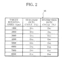
- restriction duty cycle values D R are preset in a manner associated with target rotation speed values N S .
- FIG. 2 shows a table 26 used in the motor rotation speed control.
- the table 26 is stored in memory of the MCU 20 in advance, to allow standard duty cycle values D T1 % ⁇ D T8 % and restriction duty cycle values D R1 % ⁇ D R8 % for discrete target rotation speed values N s 1000rpm ⁇ 8000rpm (with 1000rpm increments in between), for example, to be referred to.
- the standard duty cycle values D T1 % ⁇ D T8 % are theoretical output duty cycles D which can drive the motor 22 at the target rotation speeds Ns 1000rpm ⁇ 8000rpm, respectively, on the condition that the load on the motor 22 is in an allowable range.
- the restriction duty cycle values D R1 % ⁇ D R8 % are determined on the basis of the standard duty cycle values D T1 % ⁇ D T8 % for the target rotation speed values 1000rpm ⁇ 8000rpm, using a predetermined safety factor, respectively.
- the restriction duty cycle D R is used as an index of the motor 22 being overloaded. Specifically, if, during the control intending to make the actual rotation speed N R accord with the target rotation speed N S , the actual output duty cycle D exceeds the standard duty cycle D T and increases to the restriction duty cycle D R or above, it is determined that the motor 22 is overloaded.
- Standard duty cycle D T and restriction duty cycle D R used in the control are not restricted to the values in the table 26, i.e., the values for the discrete target rotation speed values N S 1000rpm ⁇ 8000rpm preset with 1000rpm increments in between.
- Standard duty cycle values D T and restriction duty cycle values D R for target rotation speed values falling between the preset target rotation speed values are obtained by so-called interpolation.
- the MCU 20 starts the control routine, and first at S1 ("S" stands for "step”; likewise in the following), determines whether or not the actual rotation speed N R is lower than the target rotation speed N S . If the determination is positive (Yes), i.e., it is determined that the actual rotation speed N R is lower than the target rotation speed N S , the MCU 20 goes to S2. If the determination is negative (No), i.e., it is determined that the actual rotation speed N R is higher than or equal to the target rotation speed N S , the MCU 20 goes to S3. It is to be noted that, as mentioned above, when the target rotation speed N S is set, the output duty cycle D is set to an initial value, i.e., a standard duty cycle value D T predetermined for the target rotation speed N S .
- the MCU 20 When going to S2, the MCU 20 refers to the table 26 and obtains a restriction duty cycle D R for the target rotation cycle N S , and then goes to S4.
- the MCU 20 When going to S3, the MCU 20 reduces the output duty cycle D (output duty cycle reduction), and returns.
- the MCU 20 determines whether or not the output duty cycle D is less than the restriction duty cycle D R . If the determination is positive (Yes), i.e., it is determined that the output duty cycle D is less than the restriction duty cycle D R , the MCU 20 goes to S5. If the determination is negative (No), i.e., it is determined that the output duty cycle D is greater than or equal to the restriction duty cycle D R , the MCU 20 determines that the motor 22 is overloaded and goes to S6.
- the MCU 20 When going to S5, the MCU 20 increases the output duty cycle D (output duty cycle increase), and returns.
- the MCU 20 When going to S6, the MCU 20 performs a process for reducing the load on the motor 22 to an allowable level (load reduction process), and returns.
- the output duty cycle D is reduced or increased to make the actual rotation speed N R accord with the target rotation speed N S .
- a process for reducing the load on the motor to an allowable level such as lowering the target rotation speed N S for the motor 22 or controlling an electronic expansion valve (not shown), is performed.
- the motor rotation speed is controlled by controlling the PMW control signal 24 appropriately, specifically by reducing or increasing the output duty cycle D on the basis of comparison between the actual rotation speed N R and the target rotation speed N S .
- the standard duty cycle D T and/or the restriction duty cycle D R can be obtained by performing interpolation on the preset values in the table 26, i.e., the standard duty cycle values D T1 % ⁇ D T8 % and restriction duty cycle values D R1 % ⁇ D R8 % associated with a specified number of target rotation speed values N S .
- This allows a reduction in the number of values to be included in the table 26, therefore a reduction in the amount of memory of the MCU 20 to be prepared for the table 26, and therefore a further reduction in the cost of the inverter drive 1.
- the inverter drive 1 is applied to a heat pump water heater, where the inverter drive 1 can easily detect the condition that a compressor constituting the heat pump water heater is overloaded, and therefore, protect the heat pump water heater in a simple and low-cost manner.
- the application of the inverter drive 1 is, however, not limited to this. The similar effect can be obtained when the inverter drive 1 is applied to refrigeration air conditioners and the like, for example.
Landscapes
- Engineering & Computer Science (AREA)
- Power Engineering (AREA)
- Control Of Ac Motors In General (AREA)
- Control Of Motors That Do Not Use Commutators (AREA)
- Control Of Non-Positive-Displacement Pumps (AREA)
Applications Claiming Priority (1)
| Application Number | Priority Date | Filing Date | Title |
|---|---|---|---|
| JP2007177118A JP2009017690A (ja) | 2007-07-05 | 2007-07-05 | インバータ制御装置及びヒートポンプ式給湯機 |
Publications (2)
| Publication Number | Publication Date |
|---|---|
| EP2012426A2 true EP2012426A2 (fr) | 2009-01-07 |
| EP2012426A3 EP2012426A3 (fr) | 2010-03-24 |
Family
ID=39768746
Family Applications (1)
| Application Number | Title | Priority Date | Filing Date |
|---|---|---|---|
| EP08158805A Withdrawn EP2012426A3 (fr) | 2007-07-05 | 2008-06-23 | Commande d'inverseur et chauffe-eau à pompe à chaleur |
Country Status (2)
| Country | Link |
|---|---|
| EP (1) | EP2012426A3 (fr) |
| JP (1) | JP2009017690A (fr) |
Cited By (6)
| Publication number | Priority date | Publication date | Assignee | Title |
|---|---|---|---|---|
| CN102347699A (zh) * | 2010-07-30 | 2012-02-08 | 日立工机株式会社 | 逆变器装置和电动工具 |
| WO2012058784A1 (fr) | 2010-11-02 | 2012-05-10 | Whirlpool Corporation | Commande de moteur d'appareil portatif équipé d'une limitation du courant basée sur la vitesse |
| WO2012124332A3 (fr) * | 2011-03-14 | 2012-11-08 | Hitachi Koki Co., Ltd. | Dispositif d'onduleur et outil de puissance électrique |
| EP3002870A1 (fr) * | 2014-10-03 | 2016-04-06 | ELICA S.p.A. | Procédé de contrôle d'un moteur électrique à aimants permanents |
| US10145586B2 (en) | 2015-01-20 | 2018-12-04 | Wacker Neuson Production Americas Llc | Flameless heater |
| WO2024111988A1 (fr) * | 2022-11-24 | 2024-05-30 | 주식회사 엘엑스세미콘 | Dispositif de pilotage de moteur, procédé de commande associé et dispositif électronique piloté par un moteur |
Families Citing this family (4)
| Publication number | Priority date | Publication date | Assignee | Title |
|---|---|---|---|---|
| JP5211006B2 (ja) * | 2009-10-02 | 2013-06-12 | 日立アプライアンス株式会社 | 冷凍サイクル装置 |
| JP2012191805A (ja) * | 2011-03-14 | 2012-10-04 | Hitachi Koki Co Ltd | インバータ装置及び電動工具 |
| JP6149479B2 (ja) * | 2013-04-12 | 2017-06-21 | 株式会社リコー | モータ制御装置、画像形成装置、モータシステム、モータ制御方法及びプログラム |
| JP7365156B2 (ja) * | 2019-07-12 | 2023-10-19 | Juki株式会社 | ミシンのモーター制御装置 |
Citations (4)
| Publication number | Priority date | Publication date | Assignee | Title |
|---|---|---|---|---|
| JPH09140151A (ja) | 1995-11-16 | 1997-05-27 | Sanyo Electric Co Ltd | インバータ制御装置 |
| EP0899862A2 (fr) | 1997-08-28 | 1999-03-03 | Barber Colman | Système et méthode de réponse en cas de panne de secteur pour un actionneur |
| US20050162114A1 (en) | 2004-01-22 | 2005-07-28 | Siemens Vdo Automotive Inc. | Overload protection for DC motors |
| EP1699130A2 (fr) | 2005-03-03 | 2006-09-06 | Sanden Corporation | Onduleur |
Family Cites Families (3)
| Publication number | Priority date | Publication date | Assignee | Title |
|---|---|---|---|---|
| JPH06205508A (ja) * | 1992-12-28 | 1994-07-22 | Kokusan Denki Co Ltd | 電動車両の速度調節方法及び装置 |
| JPH11103585A (ja) * | 1997-09-29 | 1999-04-13 | Matsushita Refrig Co Ltd | インバータ保護装置 |
| JP4742590B2 (ja) * | 2005-01-18 | 2011-08-10 | パナソニック株式会社 | モータ駆動用インバータ制御装置 |
-
2007
- 2007-07-05 JP JP2007177118A patent/JP2009017690A/ja active Pending
-
2008
- 2008-06-23 EP EP08158805A patent/EP2012426A3/fr not_active Withdrawn
Patent Citations (4)
| Publication number | Priority date | Publication date | Assignee | Title |
|---|---|---|---|---|
| JPH09140151A (ja) | 1995-11-16 | 1997-05-27 | Sanyo Electric Co Ltd | インバータ制御装置 |
| EP0899862A2 (fr) | 1997-08-28 | 1999-03-03 | Barber Colman | Système et méthode de réponse en cas de panne de secteur pour un actionneur |
| US20050162114A1 (en) | 2004-01-22 | 2005-07-28 | Siemens Vdo Automotive Inc. | Overload protection for DC motors |
| EP1699130A2 (fr) | 2005-03-03 | 2006-09-06 | Sanden Corporation | Onduleur |
Cited By (13)
| Publication number | Priority date | Publication date | Assignee | Title |
|---|---|---|---|---|
| CN102347699A (zh) * | 2010-07-30 | 2012-02-08 | 日立工机株式会社 | 逆变器装置和电动工具 |
| AU2010363617B2 (en) * | 2010-11-02 | 2016-06-02 | Whirlpool Corporation | Portable appliance motor control with speed-based current limitation |
| WO2012058784A1 (fr) | 2010-11-02 | 2012-05-10 | Whirlpool Corporation | Commande de moteur d'appareil portatif équipé d'une limitation du courant basée sur la vitesse |
| US10291172B2 (en) | 2010-11-02 | 2019-05-14 | Whirlpool Corporation | Portable appliance motor control with speed-based current limitation |
| EP2636143A4 (fr) * | 2010-11-02 | 2014-11-26 | Whirlpool Co | Commande de moteur d'appareil portatif équipé d'une limitation du courant basée sur la vitesse |
| US9780718B2 (en) | 2010-11-02 | 2017-10-03 | Whirlpool Corporation | Portable appliance motor control with speed-based current limitation |
| EP3048720A1 (fr) * | 2010-11-02 | 2016-07-27 | Whirlpool Corporation | Melangeur de moteur cc a commande directe |
| CN103348579A (zh) * | 2011-03-14 | 2013-10-09 | 日立工机株式会社 | 逆变设备和电动工具 |
| US8964429B2 (en) | 2011-03-14 | 2015-02-24 | Hitachi Koki Co., Ltd. | Inverter device and electric power tool |
| WO2012124332A3 (fr) * | 2011-03-14 | 2012-11-08 | Hitachi Koki Co., Ltd. | Dispositif d'onduleur et outil de puissance électrique |
| EP3002870A1 (fr) * | 2014-10-03 | 2016-04-06 | ELICA S.p.A. | Procédé de contrôle d'un moteur électrique à aimants permanents |
| US10145586B2 (en) | 2015-01-20 | 2018-12-04 | Wacker Neuson Production Americas Llc | Flameless heater |
| WO2024111988A1 (fr) * | 2022-11-24 | 2024-05-30 | 주식회사 엘엑스세미콘 | Dispositif de pilotage de moteur, procédé de commande associé et dispositif électronique piloté par un moteur |
Also Published As
| Publication number | Publication date |
|---|---|
| JP2009017690A (ja) | 2009-01-22 |
| EP2012426A3 (fr) | 2010-03-24 |
Similar Documents
| Publication | Publication Date | Title |
|---|---|---|
| EP2012426A2 (fr) | Commande d'inverseur et chauffe-eau à pompe à chaleur | |
| US6075328A (en) | PWM/PAM control mode switching type motor control apparatus, and motor drive and air-conditioner using the same | |
| US6924618B2 (en) | Inverter controller for driving motor, and air conditioner | |
| US7602152B2 (en) | Vehicle-use power generation control apparatus | |
| US7113414B2 (en) | Inverter control device for driving a motor and an air conditioner | |
| US9611851B2 (en) | Control method of electric compressor, controller, and refrigerator | |
| KR100397397B1 (ko) | 공기조화기 | |
| JP5902521B2 (ja) | 圧縮機モータの制御装置およびこれを搭載した空気調和機 | |
| JP2001342989A (ja) | Dcポンプの駆動制御方法 | |
| JP5501987B2 (ja) | 空気調和機 | |
| EP3340459A1 (fr) | Procédé de commande d'inverseur | |
| JP2010213518A (ja) | モータ駆動装置 | |
| JP2013024150A (ja) | 空気調和装置 | |
| KR19980043379A (ko) | 공기조화기의 압축기 주파수 천이속도 제어장치 및 그 방법 | |
| JP2009278789A (ja) | モータ駆動用インバータ制御装置 | |
| KR20070030073A (ko) | 인버터 에어컨의 구동장치 및 그 제어방법 | |
| JP3468232B2 (ja) | Pwm/pam制御形モータ駆動装置及びそれを用いた空調機 | |
| JP3316279B2 (ja) | 空気調和装置 | |
| KR19980016163A (ko) | 압축기 가변형 공조기의 직류피크전압 방지방법 | |
| JP2000227074A (ja) | 圧縮機の駆動制御方法と装置 | |
| JP2010124585A (ja) | モータ駆動用インバータ制御装置およびそれを備えた空気調和機 | |
| KR0177691B1 (ko) | 인버터 공기조화기의 압축기 운전 제어방법 | |
| JP2000234790A (ja) | マルチ形空気調和機 | |
| KR100848561B1 (ko) | 인버터의 과전압 억제를 위한 유도 전동기 감속 제어 장치및 방법 | |
| KR0143216B1 (ko) | 공기조화기의 운전제어장치 및 방법 |
Legal Events
| Date | Code | Title | Description |
|---|---|---|---|
| PUAI | Public reference made under article 153(3) epc to a published international application that has entered the european phase |
Free format text: ORIGINAL CODE: 0009012 |
|
| AK | Designated contracting states |
Kind code of ref document: A2 Designated state(s): AT BE BG CH CY CZ DE DK EE ES FI FR GB GR HR HU IE IS IT LI LT LU LV MC MT NL NO PL PT RO SE SI SK TR |
|
| AX | Request for extension of the european patent |
Extension state: AL BA MK RS |
|
| PUAL | Search report despatched |
Free format text: ORIGINAL CODE: 0009013 |
|
| AK | Designated contracting states |
Kind code of ref document: A3 Designated state(s): AT BE BG CH CY CZ DE DK EE ES FI FR GB GR HR HU IE IS IT LI LT LU LV MC MT NL NO PL PT RO SE SI SK TR |
|
| AX | Request for extension of the european patent |
Extension state: AL BA MK RS |
|
| RIC1 | Information provided on ipc code assigned before grant |
Ipc: F25B 49/02 20060101ALI20100218BHEP Ipc: H02P 27/08 20060101ALI20100218BHEP Ipc: H02P 7/28 20060101ALI20100218BHEP Ipc: H02H 7/085 20060101ALI20100218BHEP Ipc: H02P 29/02 20060101AFI20081008BHEP |
|
| 17P | Request for examination filed |
Effective date: 20100915 |
|
| 17Q | First examination report despatched |
Effective date: 20101011 |
|
| AKX | Designation fees paid |
Designated state(s): AT BE BG CH CY CZ DE DK EE ES FI FR GB GR HR HU IE IS IT LI LT LU LV MC MT NL NO PL PT RO SE SI SK TR |
|
| STAA | Information on the status of an ep patent application or granted ep patent |
Free format text: STATUS: THE APPLICATION IS DEEMED TO BE WITHDRAWN |
|
| 18D | Application deemed to be withdrawn |
Effective date: 20120613 |