EP2012613B1 - Boucle a declenchement rapide - Google Patents
Boucle a declenchement rapide Download PDFInfo
- Publication number
- EP2012613B1 EP2012613B1 EP07754468A EP07754468A EP2012613B1 EP 2012613 B1 EP2012613 B1 EP 2012613B1 EP 07754468 A EP07754468 A EP 07754468A EP 07754468 A EP07754468 A EP 07754468A EP 2012613 B1 EP2012613 B1 EP 2012613B1
- Authority
- EP
- European Patent Office
- Prior art keywords
- release lever
- release
- notch
- male component
- tongue
- Prior art date
- Legal status (The legal status is an assumption and is not a legal conclusion. Google has not performed a legal analysis and makes no representation as to the accuracy of the status listed.)
- Not-in-force
Links
- 230000000717 retained effect Effects 0.000 claims description 4
- 238000003780 insertion Methods 0.000 claims description 3
- 230000037431 insertion Effects 0.000 claims description 3
- 238000009963 fulling Methods 0.000 claims 1
- 238000010276 construction Methods 0.000 description 2
- 210000005069 ears Anatomy 0.000 description 2
- 230000009977 dual effect Effects 0.000 description 1
- 238000000926 separation method Methods 0.000 description 1
Images



Classifications
-
- A—HUMAN NECESSITIES
- A44—HABERDASHERY; JEWELLERY
- A44B—BUTTONS, PINS, BUCKLES, SLIDE FASTENERS, OR THE LIKE
- A44B11/00—Buckles; Similar fasteners for interconnecting straps or the like, e.g. for safety belts
- A44B11/25—Buckles; Similar fasteners for interconnecting straps or the like, e.g. for safety belts with two or more separable parts
- A44B11/26—Buckles; Similar fasteners for interconnecting straps or the like, e.g. for safety belts with two or more separable parts with push-button fastenings
-
- A—HUMAN NECESSITIES
- A44—HABERDASHERY; JEWELLERY
- A44B—BUTTONS, PINS, BUCKLES, SLIDE FASTENERS, OR THE LIKE
- A44B11/00—Buckles; Similar fasteners for interconnecting straps or the like, e.g. for safety belts
- A44B11/25—Buckles; Similar fasteners for interconnecting straps or the like, e.g. for safety belts with two or more separable parts
- A44B11/2592—Buckles; Similar fasteners for interconnecting straps or the like, e.g. for safety belts with two or more separable parts fastening by sliding in the main plane or a plane parallel to the main plane of the buckle
-
- A—HUMAN NECESSITIES
- A44—HABERDASHERY; JEWELLERY
- A44B—BUTTONS, PINS, BUCKLES, SLIDE FASTENERS, OR THE LIKE
- A44B11/00—Buckles; Similar fasteners for interconnecting straps or the like, e.g. for safety belts
-
- A—HUMAN NECESSITIES
- A44—HABERDASHERY; JEWELLERY
- A44B—BUTTONS, PINS, BUCKLES, SLIDE FASTENERS, OR THE LIKE
- A44B11/00—Buckles; Similar fasteners for interconnecting straps or the like, e.g. for safety belts
- A44B11/25—Buckles; Similar fasteners for interconnecting straps or the like, e.g. for safety belts with two or more separable parts
-
- Y—GENERAL TAGGING OF NEW TECHNOLOGICAL DEVELOPMENTS; GENERAL TAGGING OF CROSS-SECTIONAL TECHNOLOGIES SPANNING OVER SEVERAL SECTIONS OF THE IPC; TECHNICAL SUBJECTS COVERED BY FORMER USPC CROSS-REFERENCE ART COLLECTIONS [XRACs] AND DIGESTS
- Y10—TECHNICAL SUBJECTS COVERED BY FORMER USPC
- Y10T—TECHNICAL SUBJECTS COVERED BY FORMER US CLASSIFICATION
- Y10T24/00—Buckles, buttons, clasps, etc.
- Y10T24/45—Separable-fastener or required component thereof [e.g., projection and cavity to complete interlock]
- Y10T24/45225—Separable-fastener or required component thereof [e.g., projection and cavity to complete interlock] including member having distinct formations and mating member selectively interlocking therewith
- Y10T24/45471—Projection having movable connection between components thereof or variable configuration
- Y10T24/45524—Projection having movable connection between components thereof or variable configuration including resiliently biased projection component or surface segment
-
- Y—GENERAL TAGGING OF NEW TECHNOLOGICAL DEVELOPMENTS; GENERAL TAGGING OF CROSS-SECTIONAL TECHNOLOGIES SPANNING OVER SEVERAL SECTIONS OF THE IPC; TECHNICAL SUBJECTS COVERED BY FORMER USPC CROSS-REFERENCE ART COLLECTIONS [XRACs] AND DIGESTS
- Y10—TECHNICAL SUBJECTS COVERED BY FORMER USPC
- Y10T—TECHNICAL SUBJECTS COVERED BY FORMER US CLASSIFICATION
- Y10T24/00—Buckles, buttons, clasps, etc.
- Y10T24/45—Separable-fastener or required component thereof [e.g., projection and cavity to complete interlock]
- Y10T24/45225—Separable-fastener or required component thereof [e.g., projection and cavity to complete interlock] including member having distinct formations and mating member selectively interlocking therewith
- Y10T24/45471—Projection having movable connection between components thereof or variable configuration
- Y10T24/45524—Projection having movable connection between components thereof or variable configuration including resiliently biased projection component or surface segment
- Y10T24/45529—Requiring manual force applied against bias to interlock or disengage
-
- Y—GENERAL TAGGING OF NEW TECHNOLOGICAL DEVELOPMENTS; GENERAL TAGGING OF CROSS-SECTIONAL TECHNOLOGIES SPANNING OVER SEVERAL SECTIONS OF THE IPC; TECHNICAL SUBJECTS COVERED BY FORMER USPC CROSS-REFERENCE ART COLLECTIONS [XRACs] AND DIGESTS
- Y10—TECHNICAL SUBJECTS COVERED BY FORMER USPC
- Y10T—TECHNICAL SUBJECTS COVERED BY FORMER US CLASSIFICATION
- Y10T24/00—Buckles, buttons, clasps, etc.
- Y10T24/45—Separable-fastener or required component thereof [e.g., projection and cavity to complete interlock]
- Y10T24/45225—Separable-fastener or required component thereof [e.g., projection and cavity to complete interlock] including member having distinct formations and mating member selectively interlocking therewith
- Y10T24/45471—Projection having movable connection between components thereof or variable configuration
- Y10T24/45524—Projection having movable connection between components thereof or variable configuration including resiliently biased projection component or surface segment
- Y10T24/45545—Projection having movable connection between components thereof or variable configuration including resiliently biased projection component or surface segment forming total external surface of projection
- Y10T24/45581—Projection having movable connection between components thereof or variable configuration including resiliently biased projection component or surface segment forming total external surface of projection having inserted end formed by oppositely biased surface segments
Definitions
- This invention relates to lanyard style quick-release buckles of the type used to detachably connect straps in backpacks and the like.
- Lanyard style quick-release buckles are known, as disclosed for example by US Patent No. 6,637,083 (Howell ). While such buckles are entirely serviceable, experience has indicated that they have a number of shortcomings. For example, their design does not provide a convenient way of parting the interlocked buckle components without using the lanyard. The release levers of the female components are prone to being overstressed and broken by excessive pulling forces on the lanyards. Lanyards are limited to thin webs that are generally sewn into place, and the lanyards are susceptible to inadvertent snagging, resulting in unintended parting of the buckle components.
- EP 0,427,525 A1 and US 2,933,795 disclose alternative constructions of a quick release buckle.
- EP 1,206,916 A1 and US 5,832,573 disclose alternative constructions of quick release buckles having lanyard release cords.
- US 2006/0080811 A1 discloses a quick release buckle for use with a lanyard, and a multi-part assembly for retaining the lanyard when male and female parts of the buckle are engaged with one another.
- the objective of the present invention is to obviate or at least significantly minimize these shortcomings.
- a quick release buckle comprising:
- the lift tab may be angled upwardly to prevent the lanyard cord from obstructing the access opening of the female component's receiving channel.
- the side walls of the female component may have stops that overlap and limit the extent to which the release lever can be upwardly deflected, thus safeguarding the release lever from being excessively stressed and broken.
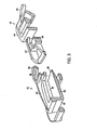
- a quick release buckle in accordance with the present invention is shown at 10.
- the buckle comprises a female component 12 connected to a web 14 by a stitched strap 16, and a male component 18 connected to another web 20.
- the female component 12 has a bottom 22 and side walls 24 coacting to define a receiving channel 26 having an access opening 28 at its front end and a rear wall 30 at its rear end.
- a resiliently deflectable release lever 32 overlies the receiving channel 26 and is supported in cantilever fashion by the rear wall 30.
- the release lever has a catch 34 on its underside, and a forward end projecting beyond the access opening at the front end of the receiving channel to define a life tab 36.
- the lift tab 36 is angled upwardly away from the access opening 28, and is provided with an aperture 38 configured and dimensioned to accept dual strands of a lanyard release cord 40.
- the male component 18 has a tongue 42 projecting forwardly from a base 44.
- a shoulder 46 on the tongue coacts in snap engagement with the catch 34 on the underside of the release lever 32 to retain the tongue in the receiving channel 26 and thus establish an interlocked relationship between the two buckle components 12, 18.
- the catch 34 can be freed from shoulder 46 to allow tongue 42 to be retracted from the deceiving channel 26, resulting in separation of the buckle components 12, 18.
- the lift tab 36 of the release lever 32 is spaced above the base 44 of the male component 18.
- the release lever 32 may be deflected upwardly either by prying or otherwise forcing the lift tab 36 upwardly, or by pulling on the lanyard release cord 40 when it is in the position shown by the broken lines at 40' in Figure 4 .
- the upwardly inclined disposition of the lift tab 36 serves to retain the lanyard release cord 40 above the access opening 28 at a location that does not interfere with insertion of the tongue 42 into the receiving channel 26.
- the base 44 of the male component 18 is advantageously provided with rearwardly projecting curved fingers 48 defining a notch 50.
- the tips of the curved fingers are spaced one from the other to define a slot 52 communicating with the notch 50.
- the lanyard cord 40 may be forced through the slot 52 and tucked into the notch 50.
- the lanyard cord is safeguarded against inadvertent snagging, which can result in the release lever 32 being pulled upwardly unintentionally.
- the side walls 24 of the female component 12 are advantageously provide with integral stops 54 positioned to overlap laterally projecting ears 56 on the release lever 32.
- the vertical spacing between the stops 54 and the ears 56 establishes a limit to upward deflection of the release lever 32.
Landscapes
- Buckles (AREA)
Abstract
Claims (4)
- Boucle à déclenchement rapide (10) comprenant :un composant femelle (12) comportant un fond (22) et des parois latérales (24) co-agissant pour délimiter un conduit de réception (26) avec une ouverture d'accès (28) à l'extrémité avant et une paroi arrière (30) à l'extrémité arrière ;un levier de déclenchement (32) superposé audit conduit de réception et porté en porte-à-faux par ladite paroi arrière, ledit levier de déclenchement comportant une languette de retenue (34) sur sa sous-face et une extrémité vers l'avant dépassant ladite extrémité avant pour définir une tirette (36), dans lequel ladite tirette comprend une ouverture ;une cordelette de déclenchement (40) enfilée dans ladite ouverture ; etun composant mâle (18) avec une languette (42) saillant vers l'avant depuis une base (44), un épaulement (46) sur ladite languette, ladite languette étant configurée et dimensionnée pour s'insérer dans ledit conduit de réception via ladite ouverture d'accès, et ledit levier de déclenchement pouvant être dévié élastiquement pour permettre un enclenchement à déclic de ladite languette de retenue avec ledit épaulement pour de ce fait retenir ledit composant mâle dans une relation de verrouillage réciproque avec ledit composant femelle, avec la tirette dudit levier de déclenchement superposé avec un espacement au dessus de la base du composant mâle ainsi retenu pour de ce fait fournir un moyen de faire dévier vers le haut ledit levier de déclenchement pour dégager ladite languette de retenue dudit épaulement et libérer ladite languette afin qu'elle puisse se retirer dudit conduit de réception,
caractérisé en ce que ledit composant mâle comprend en outre une encoche (50) à son extrémité arrière, que ladite cordelette de déclenchement est passée dans ladite encoche, moyennant quoi elle est retenue de façon amovible dans ladite encoche quand le composant mâle est enclenché avec le composant femelle. - Boucle à déclenchement rapide (10) selon la revendication 1, dans laquelle ladite tirette (36) forme un angle vers le haut à partir de ladite ouverture d'accès (28).
- Boucle à déclenchement rapide (10) selon la revendication 1, dans laquelle ladite encoche (50) est délimitée par une paire de doigts courbes (48) saillant vers l'arrière depuis ladite base (44), lesdits doigts ayant des bouts espacés l'un de l'autre qui délimitent une fente (52) dimensionnée pour permettre de glisser ladite cordelette de déclenchement (40) dans ladite encoche.
- Boucle à déclenchement rapide (10) selon la revendication 1, comprenant en outre des butées (54) sur lesdites parois latérales (24), lesdites butées étant disposées pour chevaucher ledit levier de déclenchement (32) et limiter la mesure dans laquelle il peut être dévié vers le haut.
Applications Claiming Priority (2)
| Application Number | Priority Date | Filing Date | Title |
|---|---|---|---|
| US11/415,058 US7448116B1 (en) | 2006-05-01 | 2006-05-01 | Quick release buckle |
| PCT/US2007/007952 WO2007130243A1 (fr) | 2006-05-01 | 2007-03-30 | Boucle a declenchement rapide |
Publications (2)
| Publication Number | Publication Date |
|---|---|
| EP2012613A1 EP2012613A1 (fr) | 2009-01-14 |
| EP2012613B1 true EP2012613B1 (fr) | 2011-11-02 |
Family
ID=38293145
Family Applications (1)
| Application Number | Title | Priority Date | Filing Date |
|---|---|---|---|
| EP07754468A Not-in-force EP2012613B1 (fr) | 2006-05-01 | 2007-03-30 | Boucle a declenchement rapide |
Country Status (6)
| Country | Link |
|---|---|
| US (1) | US7448116B1 (fr) |
| EP (1) | EP2012613B1 (fr) |
| KR (1) | KR101374251B1 (fr) |
| CN (2) | CN103948218A (fr) |
| CA (2) | CA2637570C (fr) |
| WO (1) | WO2007130243A1 (fr) |
Families Citing this family (33)
| Publication number | Priority date | Publication date | Assignee | Title |
|---|---|---|---|---|
| US9149596B2 (en) * | 2007-03-23 | 2015-10-06 | Resmed Limited | Release mechanism for patient interface and method for releasing patient interface |
| US8522410B2 (en) * | 2008-05-02 | 2013-09-03 | Illinois Tool Works | Buckle |
| US8074326B2 (en) * | 2009-01-12 | 2011-12-13 | Adam Slank | Strap assembly with quick release arrangement |
| US8596504B2 (en) * | 2009-01-15 | 2013-12-03 | Magpul Industries Corp | Sling Fittings and sling system for a firearm |
| US8267614B2 (en) * | 2009-04-24 | 2012-09-18 | Toyota Motor Engineering & Manufacturing North America, Inc. | Easy install guide slot with snap tab |
| US20100313392A1 (en) * | 2009-06-11 | 2010-12-16 | Joseph Anscher | Quick release buckle assembly |
| US8196273B2 (en) * | 2009-11-03 | 2012-06-12 | National Molding Llc | Quick release buckle assembly |
| GB2475255B (en) * | 2009-11-11 | 2014-07-02 | Kma Textiles Ltd | Quick Release Clip System |
| WO2011079203A1 (fr) * | 2009-12-23 | 2011-06-30 | Bae Systems Aerospace & Defense Group Inc. | Boucle à déclenchement rapide avec double libération |
| US8191213B2 (en) * | 2010-03-15 | 2012-06-05 | National Molding Llc | Quick release buckle assembly |
| US8572820B2 (en) | 2010-05-21 | 2013-11-05 | Bae Systems Specialty Defense Systems Of Pennsylvania, Inc. | Dual release buckle |
| EP2600941A4 (fr) * | 2010-08-02 | 2016-07-20 | Carleton Life Support Sys Inc | Harnais de retenue et d'évacuation doté d'un mécanisme de libération associé |
| WO2013009638A1 (fr) | 2011-07-08 | 2013-01-17 | Conax Florida Corporation | Système de retenue doté de deux mécanismes de libération |
| US8919293B2 (en) * | 2012-03-20 | 2014-12-30 | In The Lead, Llc | Self-containing, retractable leash and collar/harness assembly |
| US8807404B1 (en) * | 2013-01-09 | 2014-08-19 | Here Be Dragons, Llc | Holster retention device |
| USD717694S1 (en) | 2013-09-05 | 2014-11-18 | National Molding, Llc | Release mechanism for a buckle assembly |
| US9038251B1 (en) | 2013-10-02 | 2015-05-26 | National Molding, Llc. | Quick release buckle |
| US9743719B2 (en) | 2013-10-02 | 2017-08-29 | National Molding, Llc. | Quick release buckle |
| USD733612S1 (en) * | 2013-11-15 | 2015-07-07 | Brian Mayer | Fastener |
| US9752854B1 (en) | 2013-11-20 | 2017-09-05 | National Molding, Llc. | Holding for body mounted armor |
| US9354023B1 (en) * | 2013-11-20 | 2016-05-31 | National Molding, Llc. | Holder for body mounted armor |
| US10104943B2 (en) * | 2014-07-07 | 2018-10-23 | Abbas Haider | Pull and release latch |
| US9526301B1 (en) | 2015-06-10 | 2016-12-27 | Jill Sloan | Adaptable buckle system |
| US20180078023A1 (en) * | 2016-09-20 | 2018-03-22 | Geeknet, Inc. | Customizable modular lanyard system |
| US11571048B1 (en) * | 2018-12-19 | 2023-02-07 | Apple Inc. | Watch having a release mechanism |
| KR102188857B1 (ko) * | 2019-05-14 | 2020-12-09 | 주식회사 우진프라스틱 | 견고한 체결유지 기능과 용이한 체결해제 기능을 갖는 버클 |
| USD1014327S1 (en) | 2019-11-15 | 2024-02-13 | WHG Properties, LLC | Buckle |
| US11287214B2 (en) * | 2020-01-10 | 2022-03-29 | WHG Properties, LLC | Adjustable sling for a firearm |
| WO2022232621A1 (fr) | 2021-04-30 | 2022-11-03 | Aspetto, Inc. | Verrous pivotants à libération rapide |
| ES2995873T3 (en) | 2022-06-07 | 2025-02-11 | Due Emme Srl | Quick release clip |
| USD1108302S1 (en) * | 2022-12-21 | 2026-01-06 | Fidlock Gmbh | Buckle assembly |
| KR102575884B1 (ko) * | 2023-01-03 | 2023-09-06 | 서건수 | 힌지탈착구를 갖는 배낭용 버클 |
| KR102848085B1 (ko) * | 2023-10-10 | 2025-08-20 | 주식회사 우진프라스틱 | 버클 |
Family Cites Families (15)
| Publication number | Priority date | Publication date | Assignee | Title |
|---|---|---|---|---|
| US2933795A (en) | 1955-10-19 | 1960-04-26 | Hickok Mfg Co Inc | Safety belt buckle |
| US4679282A (en) * | 1986-06-04 | 1987-07-14 | Feng Lung S | Press fastener |
| JPH0542728Y2 (fr) * | 1987-12-28 | 1993-10-27 | ||
| JPH0746167Y2 (ja) | 1989-11-10 | 1995-10-25 | ワイケイケイ株式会社 | バックル |
| US5832573A (en) | 1996-11-14 | 1998-11-10 | Down East, Inc. | Quick release buckle assembly |
| CN2285978Y (zh) * | 1997-04-02 | 1998-07-15 | 张正安 | 带扣 |
| US6154936A (en) * | 1998-12-21 | 2000-12-05 | Down East, Inc. | Two-piece quick release buckle and strap adjuster |
| US6154935A (en) | 1999-06-02 | 2000-12-05 | Bianchi International | Quick release buckle for use on backpacks and the like |
| EP1206916A1 (fr) | 2000-11-20 | 2002-05-22 | Down East, Inc. | Boucle reglable en deux parties a ouverture rapide |
| JP4520655B2 (ja) * | 2001-03-22 | 2010-08-11 | 株式会社ニフコ | バックル |
| US7100251B2 (en) * | 2002-03-21 | 2006-09-05 | Iilinois Tool Works, Inc. | Breakaway buckle |
| US6637083B1 (en) | 2002-03-21 | 2003-10-28 | Frank A. Howell | Lanyard high load two piece buckle |
| US6678925B1 (en) * | 2002-06-02 | 2004-01-20 | Downeast, Inc. | Two-piece buckle assembly |
| JP3992194B2 (ja) * | 2003-05-07 | 2007-10-17 | 株式会社ニフコ | バックル |
| US7155786B2 (en) | 2004-10-15 | 2007-01-02 | Illinois Tool Works Inc | Quick release buckle |
-
2006
- 2006-05-01 US US11/415,058 patent/US7448116B1/en active Active
-
2007
- 2007-03-30 CN CN201410122657.5A patent/CN103948218A/zh active Pending
- 2007-03-30 KR KR1020087026666A patent/KR101374251B1/ko active Active
- 2007-03-30 WO PCT/US2007/007952 patent/WO2007130243A1/fr not_active Ceased
- 2007-03-30 CA CA2637570A patent/CA2637570C/fr active Active
- 2007-03-30 EP EP07754468A patent/EP2012613B1/fr not_active Not-in-force
- 2007-03-30 CN CNA200780008578XA patent/CN101400274A/zh active Pending
- 2007-03-30 CA CA2742132A patent/CA2742132C/fr active Active
Also Published As
| Publication number | Publication date |
|---|---|
| CA2637570C (fr) | 2011-08-23 |
| EP2012613A1 (fr) | 2009-01-14 |
| CA2742132C (fr) | 2013-07-30 |
| CN101400274A (zh) | 2009-04-01 |
| CA2637570A1 (fr) | 2007-11-15 |
| WO2007130243A1 (fr) | 2007-11-15 |
| US20080263836A1 (en) | 2008-10-30 |
| US7448116B1 (en) | 2008-11-11 |
| CA2742132A1 (fr) | 2007-11-15 |
| KR101374251B1 (ko) | 2014-03-13 |
| KR20080113432A (ko) | 2008-12-30 |
| CN103948218A (zh) | 2014-07-30 |
Similar Documents
| Publication | Publication Date | Title |
|---|---|---|
| CA2742132C (fr) | Boucle a declenchement rapide | |
| US6154936A (en) | Two-piece quick release buckle and strap adjuster | |
| EP2413732B1 (fr) | Boucle | |
| KR100413944B1 (ko) | 버클 | |
| US7155786B2 (en) | Quick release buckle | |
| EP2316295A2 (fr) | Ensemble de boucle à libération rapide | |
| US20080230069A1 (en) | Release mechanism for patient interface and method for releasing patient interface | |
| CN101511218A (zh) | 带扣结构 | |
| EP1961325B1 (fr) | Curseur pour fermeture à glissière | |
| EP2526805B1 (fr) | Curseur pour élément coulissant de fixation | |
| CA2419659C (fr) | Protege-fermeture a glissiere | |
| US7100251B2 (en) | Breakaway buckle | |
| US4977650A (en) | Buckle assembly | |
| EP1591045B1 (fr) | Boucle et porte-bébé utilisant ce boucle | |
| US20130092139A1 (en) | Quick release buckle | |
| KR101343759B1 (ko) | 버클 | |
| CN102958397B (zh) | 拉链用插接-分开件 | |
| US10349706B2 (en) | Releasable connecting device | |
| EP0719958A2 (fr) | Dispositif de blocage de corde | |
| US8464406B2 (en) | Quick release buckle assembly | |
| CN223111162U (zh) | 一种挂绳快拆扣 | |
| EP1206916A1 (fr) | Boucle reglable en deux parties a ouverture rapide | |
| US8495804B2 (en) | Quick-release buckle for a shoulder strap and preventing unintentional release when tension is exerted by the shoulder strap | |
| CN1240117A (zh) | 扣具 | |
| HK1088195A1 (zh) | 拉链 |
Legal Events
| Date | Code | Title | Description |
|---|---|---|---|
| PUAI | Public reference made under article 153(3) epc to a published international application that has entered the european phase |
Free format text: ORIGINAL CODE: 0009012 |
|
| 17P | Request for examination filed |
Effective date: 20081124 |
|
| AK | Designated contracting states |
Kind code of ref document: A1 Designated state(s): AT BE BG CH CY CZ DE DK EE ES FI FR GB GR HU IE IS IT LI LT LU LV MC MT NL PL PT RO SE SI SK TR |
|
| AX | Request for extension of the european patent |
Extension state: AL BA HR MK RS |
|
| 17Q | First examination report despatched |
Effective date: 20090313 |
|
| RBV | Designated contracting states (corrected) |
Designated state(s): DE ES GB SE |
|
| DAX | Request for extension of the european patent (deleted) | ||
| GRAP | Despatch of communication of intention to grant a patent |
Free format text: ORIGINAL CODE: EPIDOSNIGR1 |
|
| GRAS | Grant fee paid |
Free format text: ORIGINAL CODE: EPIDOSNIGR3 |
|
| GRAA | (expected) grant |
Free format text: ORIGINAL CODE: 0009210 |
|
| AK | Designated contracting states |
Kind code of ref document: B1 Designated state(s): DE ES GB SE |
|
| REG | Reference to a national code |
Ref country code: GB Ref legal event code: FG4D |
|
| REG | Reference to a national code |
Ref country code: DE Ref legal event code: R096 Ref document number: 602007018474 Country of ref document: DE Effective date: 20120112 |
|
| PG25 | Lapsed in a contracting state [announced via postgrant information from national office to epo] |
Ref country code: SE Free format text: LAPSE BECAUSE OF FAILURE TO SUBMIT A TRANSLATION OF THE DESCRIPTION OR TO PAY THE FEE WITHIN THE PRESCRIBED TIME-LIMIT Effective date: 20111102 |
|
| PLBE | No opposition filed within time limit |
Free format text: ORIGINAL CODE: 0009261 |
|
| STAA | Information on the status of an ep patent application or granted ep patent |
Free format text: STATUS: NO OPPOSITION FILED WITHIN TIME LIMIT |
|
| 26N | No opposition filed |
Effective date: 20120803 |
|
| REG | Reference to a national code |
Ref country code: DE Ref legal event code: R097 Ref document number: 602007018474 Country of ref document: DE Effective date: 20120803 |
|
| PG25 | Lapsed in a contracting state [announced via postgrant information from national office to epo] |
Ref country code: ES Free format text: LAPSE BECAUSE OF FAILURE TO SUBMIT A TRANSLATION OF THE DESCRIPTION OR TO PAY THE FEE WITHIN THE PRESCRIBED TIME-LIMIT Effective date: 20120213 |
|
| PGFP | Annual fee paid to national office [announced via postgrant information from national office to epo] |
Ref country code: DE Payment date: 20130327 Year of fee payment: 7 Ref country code: GB Payment date: 20130327 Year of fee payment: 7 |
|
| REG | Reference to a national code |
Ref country code: DE Ref legal event code: R119 Ref document number: 602007018474 Country of ref document: DE |
|
| GBPC | Gb: european patent ceased through non-payment of renewal fee |
Effective date: 20140330 |
|
| REG | Reference to a national code |
Ref country code: DE Ref legal event code: R119 Ref document number: 602007018474 Country of ref document: DE Effective date: 20141001 |
|
| PG25 | Lapsed in a contracting state [announced via postgrant information from national office to epo] |
Ref country code: GB Free format text: LAPSE BECAUSE OF NON-PAYMENT OF DUE FEES Effective date: 20140330 Ref country code: DE Free format text: LAPSE BECAUSE OF NON-PAYMENT OF DUE FEES Effective date: 20141001 |