EP2316295A2 - Ensemble de boucle à libération rapide - Google Patents
Ensemble de boucle à libération rapide Download PDFInfo
- Publication number
- EP2316295A2 EP2316295A2 EP10187900A EP10187900A EP2316295A2 EP 2316295 A2 EP2316295 A2 EP 2316295A2 EP 10187900 A EP10187900 A EP 10187900A EP 10187900 A EP10187900 A EP 10187900A EP 2316295 A2 EP2316295 A2 EP 2316295A2
- Authority
- EP
- European Patent Office
- Prior art keywords
- cable
- buckle
- locking
- release
- male
- Prior art date
- Legal status (The legal status is an assumption and is not a legal conclusion. Google has not performed a legal analysis and makes no representation as to the accuracy of the status listed.)
- Granted
Links
Images


Classifications
-
- A—HUMAN NECESSITIES
- A44—HABERDASHERY; JEWELLERY
- A44B—BUTTONS, PINS, BUCKLES, SLIDE FASTENERS, OR THE LIKE
- A44B11/00—Buckles; Similar fasteners for interconnecting straps or the like, e.g. for safety belts
- A44B11/25—Buckles; Similar fasteners for interconnecting straps or the like, e.g. for safety belts with two or more separable parts
- A44B11/26—Buckles; Similar fasteners for interconnecting straps or the like, e.g. for safety belts with two or more separable parts with push-button fastenings
- A44B11/266—Buckles; Similar fasteners for interconnecting straps or the like, e.g. for safety belts with two or more separable parts with push-button fastenings with at least one push-button acting parallel to the main plane of the buckle and perpendicularly to the direction of the fastening action
-
- F—MECHANICAL ENGINEERING; LIGHTING; HEATING; WEAPONS; BLASTING
- F41—WEAPONS
- F41H—ARMOUR; ARMOURED TURRETS; ARMOURED OR ARMED VEHICLES; MEANS OF ATTACK OR DEFENCE, e.g. CAMOUFLAGE, IN GENERAL
- F41H1/00—Personal protection gear
- F41H1/02—Armoured or projectile- or missile-resistant garments; Composite protection fabrics
-
- A—HUMAN NECESSITIES
- A41—WEARING APPAREL
- A41D—OUTERWEAR; PROTECTIVE GARMENTS; ACCESSORIES
- A41D2400/00—Functions or special features of garments
- A41D2400/44—Donning facilities
-
- A—HUMAN NECESSITIES
- A44—HABERDASHERY; JEWELLERY
- A44B—BUTTONS, PINS, BUCKLES, SLIDE FASTENERS, OR THE LIKE
- A44B11/00—Buckles; Similar fasteners for interconnecting straps or the like, e.g. for safety belts
- A44B11/25—Buckles; Similar fasteners for interconnecting straps or the like, e.g. for safety belts with two or more separable parts
- A44B11/2503—Safety buckles
- A44B11/2546—Details
- A44B11/2553—Attachment of buckle to strap
-
- Y—GENERAL TAGGING OF NEW TECHNOLOGICAL DEVELOPMENTS; GENERAL TAGGING OF CROSS-SECTIONAL TECHNOLOGIES SPANNING OVER SEVERAL SECTIONS OF THE IPC; TECHNICAL SUBJECTS COVERED BY FORMER USPC CROSS-REFERENCE ART COLLECTIONS [XRACs] AND DIGESTS
- Y10—TECHNICAL SUBJECTS COVERED BY FORMER USPC
- Y10T—TECHNICAL SUBJECTS COVERED BY FORMER US CLASSIFICATION
- Y10T24/00—Buckles, buttons, clasps, etc.
- Y10T24/34—Combined diverse multipart fasteners
- Y10T24/3401—Buckle
- Y10T24/3403—Buckle and buckles
- Y10T24/3405—Buckle and buckles having separate disconnect means
-
- Y—GENERAL TAGGING OF NEW TECHNOLOGICAL DEVELOPMENTS; GENERAL TAGGING OF CROSS-SECTIONAL TECHNOLOGIES SPANNING OVER SEVERAL SECTIONS OF THE IPC; TECHNICAL SUBJECTS COVERED BY FORMER USPC CROSS-REFERENCE ART COLLECTIONS [XRACs] AND DIGESTS
- Y10—TECHNICAL SUBJECTS COVERED BY FORMER USPC
- Y10T—TECHNICAL SUBJECTS COVERED BY FORMER US CLASSIFICATION
- Y10T24/00—Buckles, buttons, clasps, etc.
- Y10T24/34—Combined diverse multipart fasteners
- Y10T24/3401—Buckle
- Y10T24/3403—Buckle and buckles
- Y10T24/3408—Buckle and buckles having disconnect structure
-
- Y—GENERAL TAGGING OF NEW TECHNOLOGICAL DEVELOPMENTS; GENERAL TAGGING OF CROSS-SECTIONAL TECHNOLOGIES SPANNING OVER SEVERAL SECTIONS OF THE IPC; TECHNICAL SUBJECTS COVERED BY FORMER USPC CROSS-REFERENCE ART COLLECTIONS [XRACs] AND DIGESTS
- Y10—TECHNICAL SUBJECTS COVERED BY FORMER USPC
- Y10T—TECHNICAL SUBJECTS COVERED BY FORMER US CLASSIFICATION
- Y10T24/00—Buckles, buttons, clasps, etc.
- Y10T24/45—Separable-fastener or required component thereof [e.g., projection and cavity to complete interlock]
- Y10T24/45005—Separable-fastener or required component thereof [e.g., projection and cavity to complete interlock] with third detached member completing interlock [e.g., hook type]
- Y10T24/4501—Quick connect or release [e.g., spring and detent]
-
- Y—GENERAL TAGGING OF NEW TECHNOLOGICAL DEVELOPMENTS; GENERAL TAGGING OF CROSS-SECTIONAL TECHNOLOGIES SPANNING OVER SEVERAL SECTIONS OF THE IPC; TECHNICAL SUBJECTS COVERED BY FORMER USPC CROSS-REFERENCE ART COLLECTIONS [XRACs] AND DIGESTS
- Y10—TECHNICAL SUBJECTS COVERED BY FORMER USPC
- Y10T—TECHNICAL SUBJECTS COVERED BY FORMER US CLASSIFICATION
- Y10T24/00—Buckles, buttons, clasps, etc.
- Y10T24/45—Separable-fastener or required component thereof [e.g., projection and cavity to complete interlock]
- Y10T24/45225—Separable-fastener or required component thereof [e.g., projection and cavity to complete interlock] including member having distinct formations and mating member selectively interlocking therewith
- Y10T24/45471—Projection having movable connection between components thereof or variable configuration
- Y10T24/45482—Projection having movable connection between components thereof or variable configuration and operator therefor
-
- Y—GENERAL TAGGING OF NEW TECHNOLOGICAL DEVELOPMENTS; GENERAL TAGGING OF CROSS-SECTIONAL TECHNOLOGIES SPANNING OVER SEVERAL SECTIONS OF THE IPC; TECHNICAL SUBJECTS COVERED BY FORMER USPC CROSS-REFERENCE ART COLLECTIONS [XRACs] AND DIGESTS
- Y10—TECHNICAL SUBJECTS COVERED BY FORMER USPC
- Y10T—TECHNICAL SUBJECTS COVERED BY FORMER US CLASSIFICATION
- Y10T24/00—Buckles, buttons, clasps, etc.
- Y10T24/45—Separable-fastener or required component thereof [e.g., projection and cavity to complete interlock]
- Y10T24/45225—Separable-fastener or required component thereof [e.g., projection and cavity to complete interlock] including member having distinct formations and mating member selectively interlocking therewith
- Y10T24/45471—Projection having movable connection between components thereof or variable configuration
- Y10T24/45524—Projection having movable connection between components thereof or variable configuration including resiliently biased projection component or surface segment
-
- Y—GENERAL TAGGING OF NEW TECHNOLOGICAL DEVELOPMENTS; GENERAL TAGGING OF CROSS-SECTIONAL TECHNOLOGIES SPANNING OVER SEVERAL SECTIONS OF THE IPC; TECHNICAL SUBJECTS COVERED BY FORMER USPC CROSS-REFERENCE ART COLLECTIONS [XRACs] AND DIGESTS
- Y10—TECHNICAL SUBJECTS COVERED BY FORMER USPC
- Y10T—TECHNICAL SUBJECTS COVERED BY FORMER US CLASSIFICATION
- Y10T24/00—Buckles, buttons, clasps, etc.
- Y10T24/45—Separable-fastener or required component thereof [e.g., projection and cavity to complete interlock]
- Y10T24/45225—Separable-fastener or required component thereof [e.g., projection and cavity to complete interlock] including member having distinct formations and mating member selectively interlocking therewith
- Y10T24/45471—Projection having movable connection between components thereof or variable configuration
- Y10T24/45524—Projection having movable connection between components thereof or variable configuration including resiliently biased projection component or surface segment
- Y10T24/45529—Requiring manual force applied against bias to interlock or disengage
-
- Y—GENERAL TAGGING OF NEW TECHNOLOGICAL DEVELOPMENTS; GENERAL TAGGING OF CROSS-SECTIONAL TECHNOLOGIES SPANNING OVER SEVERAL SECTIONS OF THE IPC; TECHNICAL SUBJECTS COVERED BY FORMER USPC CROSS-REFERENCE ART COLLECTIONS [XRACs] AND DIGESTS
- Y10—TECHNICAL SUBJECTS COVERED BY FORMER USPC
- Y10T—TECHNICAL SUBJECTS COVERED BY FORMER US CLASSIFICATION
- Y10T24/00—Buckles, buttons, clasps, etc.
- Y10T24/45—Separable-fastener or required component thereof [e.g., projection and cavity to complete interlock]
- Y10T24/45225—Separable-fastener or required component thereof [e.g., projection and cavity to complete interlock] including member having distinct formations and mating member selectively interlocking therewith
- Y10T24/45602—Receiving member includes either movable connection between interlocking components or variable configuration cavity
-
- Y—GENERAL TAGGING OF NEW TECHNOLOGICAL DEVELOPMENTS; GENERAL TAGGING OF CROSS-SECTIONAL TECHNOLOGIES SPANNING OVER SEVERAL SECTIONS OF THE IPC; TECHNICAL SUBJECTS COVERED BY FORMER USPC CROSS-REFERENCE ART COLLECTIONS [XRACs] AND DIGESTS
- Y10—TECHNICAL SUBJECTS COVERED BY FORMER USPC
- Y10T—TECHNICAL SUBJECTS COVERED BY FORMER US CLASSIFICATION
- Y10T24/00—Buckles, buttons, clasps, etc.
- Y10T24/45—Separable-fastener or required component thereof [e.g., projection and cavity to complete interlock]
- Y10T24/45225—Separable-fastener or required component thereof [e.g., projection and cavity to complete interlock] including member having distinct formations and mating member selectively interlocking therewith
- Y10T24/45984—Cavity having specific shape
- Y10T24/4599—Cavity having specific shape including closed elongated access opening for guiding transverse projection travel after insertion
-
- Y—GENERAL TAGGING OF NEW TECHNOLOGICAL DEVELOPMENTS; GENERAL TAGGING OF CROSS-SECTIONAL TECHNOLOGIES SPANNING OVER SEVERAL SECTIONS OF THE IPC; TECHNICAL SUBJECTS COVERED BY FORMER USPC CROSS-REFERENCE ART COLLECTIONS [XRACs] AND DIGESTS
- Y10—TECHNICAL SUBJECTS COVERED BY FORMER USPC
- Y10T—TECHNICAL SUBJECTS COVERED BY FORMER US CLASSIFICATION
- Y10T24/00—Buckles, buttons, clasps, etc.
- Y10T24/47—Strap-end-attaching devices
- Y10T24/4736—Buckle connected
Definitions
- This invention relates to a quick release buckle assembly.
- the invention relates to a quick-release buckle assembly that can be used on articles of clothing such as cut away vest that need to be quickly and easily removed by the wearer.
- Cut away vests are often worn by members of the military and law enforcement agencies to aid the wearer in carrying gear, as well as to protect against bullets and other impacts. These vests, especially when loaded with armor plating, can be very heavy and cumbersome to wear. Therefore it is a requirement that the vests be easily removable by the wearer, in case the wearer must be mobile in an emergency, and especially in case of submersion in water.
- a quick-release buckle system is described in United States Patent No. 6,487,761 .
- a cable system is directly attached to the locking legs of the male portion of the buckle so that pulling the cable pulls the legs inward.
- This buckle has the disadvantage that it is difficult to mold, and it compromises the strength of the locking legs, because they have to be made especially flexible to be able to be moved by the cable.
- a version of this cut-away vest is described in United States Patent Application Serial No. 12/456,069 , the disclosure of which is herein incorporated by reference.
- a quick release buckle assembly having a male portion that is inserted into a female portion. Each male buckle portion is connected to a cable. A sharp pull on the cable causes the male portion to release from the female portion to separate the buckle assembly.
- Each female portion comprises a hollow body with a front wall, a back wall, an open top, a cavity between the front and back walls and at least one locking slot extending through the hollow body and communicating with the cavity.
- Each male portion comprises a base with at least one locking leg, such that inserting the male part into the open top of the female part causes the locking leg to engage the locking slot to lock the male portion to the female portion, as is the case with traditional side-release buckles.
- the operation of a traditional side-release buckle such as that described in United States Patent No. 5,794,316 , is well known and not described in detail here.
- the male portion also be released in the traditional manner: by pinching the locking legs together from outside the female buckle portion until they clear the locking slots in the female portion.
- the buckle used in the present invention has an additional feature: In this buckle, there are means for moving the locking legs inward to release the male portion from the female portion when a cable is pulled.
- the means for moving the locking leg toward the central leg can comprise a separate release assembly that is positioned at the tip of the locking legs.
- the release assembly is a separate piece that is not connected to the locking legs.
- the release assembly is slidable toward the base of the male portion. This sliding movement causes the locking legs to be pinched inward to release them from the locking slots of the female portion.
- the release assembly comprises a horizontal bar with two arms that extend down toward the base of the male portion, so that the release assembly wraps around the tips of the locking legs.
- the arms have a slanted inner contour, which slants outwards toward the base of the male portion.
- the locking legs have a rounded or slanted tip, which widens toward the legs, corresponding to the outward slant of the arms of the release assembly. Sliding the release assembly toward the base causes the arms to slide along the tips of the locking legs and press the locking legs inward until they clear the locking slots of the female portion.
- the tips of the locking legs have a locking element at their widest point, to catch on the edge of the locking slots to keep the male portion firmly secured to the female portion until the release assembly is slid down to press the legs inward.
- the release assembly is connected to a cable running through the male portion, so that pulling the cable causes the release assembly to slide toward the base and push the locking legs inward.
- the cable extends through a central leg of the male portion and attaches at a central point of the release assembly.
- the release assembly can have a cable guide that extends into a channel in the central leg. The cable then connects to the cable guide. This arrangement ensures that the release assembly does not move out of the plane of the buckle assembly, and only moves in its designated sliding direction.
- Insertion of the cable into the cable guide is a simple procedure.
- the release assembly is fully depressed, so that the locking legs are squeezed together.
- the end of the cable guide is pushed through the central leg of the male portion and extends beyond the central leg.
- the cable has an enlarged end section, which is placed in an aperture at the end of the cable guide to secure the cable to the cable guide.
- the aperture is connected to the end of the cable guide by a slot through which the cable extends.
- the release assembly is then released back into its resting position, with the cable secured in the cable guide.
- the cable can then be easily removed in the same way.
- the release assembly can be fully depressed to reveal the end of the cable in the cable guide.
- the buckle assembly according to the invention has the advantage that several buckle assemblies can be connected via their cables, so that a single pull can release all of the connected buckle assemblies at the same time.
- the cables of each of the male portions can be attached to a single handle, so that pulling the handle releases all of the buckle assemblies simultaneously. This allows a device that is being held together by several buckles to be immediately disassembled with a single motion.
- the buckle assembly could be used to secure the front and back sections of a cut away vest to each other, as described in US Patent Application No. 12/456,069 . Pulling the handle causes all of the male portions to simultaneously release from the female portions and release the front portion of the vest from the rear portion, allowing the wearer to be immediately freed from the vest.
- the base of the male buckle portion has a strap securing bar that is connected to the base at one end, and has a releasable latch at the other end.
- the latch can be secured in an aperture on the base of the male portion to create a secure strap bar on the end of the male portion.
- the male portion can be attached to a length of webbing without needing a free end of the webbing to thread through a bar on the buckle. This is especially important if the buckle is to be secured to a military vest, because these vests often only have webbing that is secured to the vest on both ends.
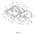
- FIGS. 1-7 show a male buckle portion 10 according to an embodiment of the invention.
- Male buckle portion 10 has a base II, and two locking legs 12, 13. Each locking leg 12, 13 has a locking element 14, 15, on its respective end. Extending from base 11 is a hollow central leg 16, through which a cable 35 extends. Cable 35 is connected to a release assembly 20, which forms a separate piece from male buckle portion 10.
- a cable sheath 36 can surround cable 35 outside male portion 10 so the cable sheath 36 can be attached to a structure and cable 35 can slide within cable sheath 36 to operate the buckle assembly.
- Release assembly 20 has a horizontal base 21 and two arms 22, 23 extending back toward base 11 of male buckle portion 10. Extending down from horizontal base 21 is a cable guide 24 that inserts into a channel 19 in central leg 16 of male buckle portion 10. Cable 35 extends into central leg 16 and attaches to cable guide 24 of release assembly 20.
- Arms 22, 23 of release assembly 20 have a slanted interior surface 25, 26 which is angled outward toward the ends of arms 22, 23, so that the inner contour of release assembly 20 widens as it extends away from horizontal base 21.
- Locking elements 14, 15 have a curved structure that widens from the tip to the bottom of locking elements 14, 15, which ends in ledges 18, 19.
- Ledges 18, 19 serve to secure locking elements 18, 19 within locking slots 31 of a corresponding female buckle portion 30, such as shown in FIG. 6 .
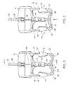
- release assembly 20 In use, when cable 35 is pulled, release assembly 20 is pulled toward base 11 and presses against locking elements 14, 15 of male portion 10.
- the slanted inner surfaces 25, 26 slide along the curved outer surface of locking elements 14, 15 and press locking elements 14, 15 inward as the inner contour of release assembly 20 narrows toward the top, as shown in FIG. 3 .
- release assembly 20 Once release assembly 20 has been fully lowered, locking legs 12,13 have been sufficiently pressed inward to allow locking elements 14, 15 to clear locking slots 31 of female buckle portion 30.
- male portion 20 is released from female portion 30 and is pulled out by the force on cable 35.
- Female portion 30 is configured similar to female buckle portions on standard side-release buckles, except that extra room is made to accommodate release assembly 20 inside its cavity, as shown in FIG. 6 .
- cable 35 can be easily inserted and disengaged from male portion 10, so that a buckle can be replaced at any time.
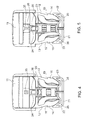
- release assembly 20 is placed into a fully depressed position, as shown in FIG. 4 . This exposes aperture 29 in cable guide 24 which is accessible through a slot 26 at the end of cable guide 24.
- cable 35 which has enlarged end portion 38, is placed in slot 26 so that enlarged end portion 38 rests within aperture 29.
- Enlarged end portion 38 is wider than slot 26 so it cannot slide out of cable guide 24.
- Release assembly 20 is then released so that it slides back up into central leg 16 of male buckle portion 10. Since slot 26 is now concealed within central leg 16, cable 35 cannot be removed, and cable 35 is securely attached to cable guide 24.
- cable 35 can be easily removed from cable guide 24 by depressing release assembly 20 until slot 26 and aperture 29 clear central leg 16, and cable 35 can be simply lifted out of cable guide 24. This allows defective or broken buckles to be replaced without having to replace the cable or any other parts of the object to which the cable is attached.
- the buckle assembly of the present invention can be used in a multiple-buckle system, where several buckles need to be released simultaneously.
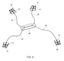
- the system which is shown in FIG. 7 , several male portions 10 with their release assemblies 20 are connected to cables 35, which are all connected to a single handle 40.
- a hard pull on handle 40 pulls all four cables 35, which simultaneously causes all of release assemblies 20 to slide down and release the locking legs from the corresponding female buckle portions 30.
- This system is ideal for a cut-away vest such as described in U.S. Patent Application No. 12/456,069 , but can also be used for many other applications.
- FIG. 10 Another embodiment of the buckle assembly is shown in FIG. 10 .
- the rear section of male buckle portion 10 has a strap retaining bar 40, which is connected at one end to strut 46 of male buckle portion 10.
- a latch 45 is disposed, which can be snapped into a corresponding aperture 49 in strut 47 of male buckle portion 10 to secure strap retaining bar 40 securely to male portion 10.
- Struts 46, and 47 are flexible so that bending the struts away from each other releases latch 45 from the aperture 49.
- Shoulder sections 41, 42 enable strap retaining bar to be easily unlocked, because shoulder sections 41, 42 extend beyond the width of side struts 46, 47 and provide good leverage for a user's thumbs and fingers to pry apart struts 46, 47 to release strap retaining bar 40.
Landscapes
- Engineering & Computer Science (AREA)
- General Engineering & Computer Science (AREA)
- Buckles (AREA)
- Details Of Connecting Devices For Male And Female Coupling (AREA)
Applications Claiming Priority (1)
| Application Number | Priority Date | Filing Date | Title |
|---|---|---|---|
| US12/590,170 US8196273B2 (en) | 2009-11-03 | 2009-11-03 | Quick release buckle assembly |
Publications (3)
| Publication Number | Publication Date |
|---|---|
| EP2316295A2 true EP2316295A2 (fr) | 2011-05-04 |
| EP2316295A3 EP2316295A3 (fr) | 2011-08-03 |
| EP2316295B1 EP2316295B1 (fr) | 2013-08-14 |
Family
ID=43290109
Family Applications (1)
| Application Number | Title | Priority Date | Filing Date |
|---|---|---|---|
| EP10187900.5A Active EP2316295B1 (fr) | 2009-11-03 | 2010-10-18 | Ensemble de boucle à libération rapide |
Country Status (2)
| Country | Link |
|---|---|
| US (1) | US8196273B2 (fr) |
| EP (1) | EP2316295B1 (fr) |
Cited By (3)
| Publication number | Priority date | Publication date | Assignee | Title |
|---|---|---|---|---|
| AT511348A4 (de) * | 2011-05-31 | 2012-11-15 | Aba Hoertnagl Gmbh | Schnallenanordnung |
| US9198481B2 (en) | 2010-10-14 | 2015-12-01 | Aba Hörtnagl Gmbh | Buckle |
| EP4520217A4 (fr) * | 2022-06-15 | 2026-01-07 | Qiuzong Li | Dispositif de boucle à déverrouillage rapide de liaison et gilet pare-balles à libération rapide |
Families Citing this family (36)
| Publication number | Priority date | Publication date | Assignee | Title |
|---|---|---|---|---|
| US9562746B2 (en) | 2007-10-08 | 2017-02-07 | Mku Pvt Ltd | Quickly releasable vest |
| EP2286173A2 (fr) * | 2008-05-22 | 2011-02-23 | Paul Carter | Système et procédé permettant une libération rapide |
| WO2009143464A2 (fr) * | 2008-05-22 | 2009-11-26 | Paul Carter | Libération de port de charge personnelle |
| US20120174276A1 (en) * | 2009-01-14 | 2012-07-12 | Thomas Craffey | Ballistic vest |
| US8201271B2 (en) * | 2009-11-19 | 2012-06-19 | Guardian Protective Technologies Inc. | Armor vest with mechanical quick release mechanism |
| EP3138609B1 (fr) * | 2010-08-02 | 2017-12-06 | Carleton Life Support Systems Inc. | Harnais de retenue et d'évacuation doté d'un mécanisme de libération associé |
| US20120030852A1 (en) * | 2010-08-03 | 2012-02-09 | Joseph Anscher | Multiple buckle release system |
| US20130081236A1 (en) * | 2010-08-16 | 2013-04-04 | Illinois Tool Works Inc. | Buckle assembly |
| US8978942B2 (en) * | 2010-11-10 | 2015-03-17 | Brian K. Bell | Quick release watch band |
| WO2012158869A1 (fr) * | 2011-05-18 | 2012-11-22 | Illinois Tool Works Inc. | Boucle de sangle comportant un mécanisme de libération |
| US9610917B2 (en) | 2011-07-08 | 2017-04-04 | Carleton Life Support Systems, Inc. | Restraint system with dual release mechanisms |
| US8919293B2 (en) * | 2012-03-20 | 2014-12-30 | In The Lead, Llc | Self-containing, retractable leash and collar/harness assembly |
| JP6029741B2 (ja) * | 2013-03-12 | 2016-11-24 | Ykk株式会社 | バックル |
| US9204692B2 (en) * | 2013-05-22 | 2015-12-08 | Leon Sports Ltd. | Quick release buckle |
| USD717694S1 (en) | 2013-09-05 | 2014-11-18 | National Molding, Llc | Release mechanism for a buckle assembly |
| RU2016114661A (ru) * | 2013-09-16 | 2017-10-23 | ЭмКейЮ ПВТ ЛТД | Жилет с возможностью быстрого отсоединения |
| US9038251B1 (en) * | 2013-10-02 | 2015-05-26 | National Molding, Llc. | Quick release buckle |
| US9743719B2 (en) | 2013-10-02 | 2017-08-29 | National Molding, Llc. | Quick release buckle |
| US10893708B1 (en) | 2013-10-21 | 2021-01-19 | Blue Force Gear, Inc. | Utility garment |
| US9354023B1 (en) | 2013-11-20 | 2016-05-31 | National Molding, Llc. | Holder for body mounted armor |
| US9752854B1 (en) | 2013-11-20 | 2017-09-05 | National Molding, Llc. | Holding for body mounted armor |
| US9003947B1 (en) | 2013-11-20 | 2015-04-14 | National Molding, Llc | Holder for body mounted armor |
| GB201409842D0 (en) | 2014-06-03 | 2014-07-16 | Bcb Int Ltd | Body armour with integrated floatation |
| WO2016007458A1 (fr) * | 2014-07-07 | 2016-01-14 | Mystery Ranch, Ltd. | Veste militaire et boucle à ouverture rapide à connecteurs électriques |
| US20160114656A1 (en) * | 2014-10-28 | 2016-04-28 | Hyundai Motor Company | Door curtain for vehicles |
| US9526301B1 (en) * | 2015-06-10 | 2016-12-27 | Jill Sloan | Adaptable buckle system |
| US9820534B1 (en) * | 2015-09-02 | 2017-11-21 | Todd A. Kelley | Wireless quick release buckle |
| TWI566717B (zh) * | 2015-09-18 | 2017-01-21 | 武倢工業有限公司 | 扣具 |
| AT520047B1 (de) * | 2017-06-14 | 2019-10-15 | Ing Hans Julian Dzugan | Auffanggurtvorrichtung |
| TWI642376B (zh) * | 2017-12-06 | 2018-12-01 | 宇超實業有限公司 | 扣具及其插頭扣件 |
| US10631664B2 (en) * | 2018-01-16 | 2020-04-28 | Mi Brands, Llc | Two-piece baby carrier |
| US11571048B1 (en) * | 2018-12-19 | 2023-02-07 | Apple Inc. | Watch having a release mechanism |
| CN110495685B (zh) * | 2019-08-22 | 2024-02-20 | 联扬塑胶(深圳)有限公司 | 扣具 |
| KR102500649B1 (ko) * | 2021-05-17 | 2023-02-23 | 이근열 | 끈 작동형 버클 |
| PL438823A1 (pl) * | 2021-08-26 | 2023-02-27 | Krzysztof Pędzisz | Szybkorozpinalna kamizelka ochronna, układ szybkiego zwalniania oraz klamra zatrzaskowa |
| TWI838839B (zh) * | 2022-08-31 | 2024-04-11 | 啟碁科技股份有限公司 | 電子裝置、及承載式扣具與其承載架 |
Citations (3)
| Publication number | Priority date | Publication date | Assignee | Title |
|---|---|---|---|---|
| US5794316A (en) | 1996-06-24 | 1998-08-18 | National Molding Corp. | Side-release buckle having improved locking feature |
| US6487761B2 (en) | 2001-01-17 | 2002-12-03 | Charles E. Van Tassel | Quick release buckle for divers |
| US7243376B2 (en) | 2003-07-08 | 2007-07-17 | Eagle Industries Unlimited, Inc. | Cut away vest |
Family Cites Families (16)
| Publication number | Priority date | Publication date | Assignee | Title |
|---|---|---|---|---|
| DE1849648U (de) | 1961-10-11 | 1962-04-05 | Tig Tech Industrieprodukte G M | Kugelsichere fliegerweste. |
| US3200463A (en) * | 1962-12-10 | 1965-08-17 | Capewell Mfg Company | Quick-release connector |
| DE9102006U1 (de) * | 1991-02-20 | 1991-06-20 | TRW Repa GmbH, 7077 Alfdorf | Betätigungseinrichtung für ein Gurtschloß in einem Sicherheitsgurtsystem |
| TW301145U (en) * | 1993-10-16 | 1997-03-21 | Yoshida Kogyo Kk | Buckle |
| US5832573A (en) * | 1996-11-14 | 1998-11-10 | Down East, Inc. | Quick release buckle assembly |
| US7073234B2 (en) * | 2002-02-14 | 2006-07-11 | Aqua Lung America, Inc. | Quick-release buckle |
| JP4128101B2 (ja) * | 2003-04-11 | 2008-07-30 | Ykk株式会社 | バックル |
| US6931695B2 (en) * | 2003-12-18 | 2005-08-23 | Joseph Anscher | Buckle with push button release |
| US7448116B1 (en) * | 2006-05-01 | 2008-11-11 | Illinois Tool Works Inc. | Quick release buckle |
| US20110179539A1 (en) | 2006-06-09 | 2011-07-28 | Dovner Edward R | Protective garment system with weight transfer elements |
| WO2009047790A2 (fr) | 2007-10-08 | 2009-04-16 | Mku Pvt Ltd | Gilet détachable rapidement |
| DE102007058124A1 (de) | 2007-11-30 | 2009-06-04 | Mehler Vario System Gmbh | Verschlussvorrichtung zum lösbaren Verbinden von Gurten, Bändern und dergleichen Zugelementen |
| US8522410B2 (en) * | 2008-05-02 | 2013-09-03 | Illinois Tool Works | Buckle |
| EP2286173A2 (fr) * | 2008-05-22 | 2011-02-23 | Paul Carter | Système et procédé permettant une libération rapide |
| US20100313392A1 (en) * | 2009-06-11 | 2010-12-16 | Joseph Anscher | Quick release buckle assembly |
| US8191213B2 (en) * | 2010-03-15 | 2012-06-05 | National Molding Llc | Quick release buckle assembly |
-
2009
- 2009-11-03 US US12/590,170 patent/US8196273B2/en active Active
-
2010
- 2010-10-18 EP EP10187900.5A patent/EP2316295B1/fr active Active
Patent Citations (3)
| Publication number | Priority date | Publication date | Assignee | Title |
|---|---|---|---|---|
| US5794316A (en) | 1996-06-24 | 1998-08-18 | National Molding Corp. | Side-release buckle having improved locking feature |
| US6487761B2 (en) | 2001-01-17 | 2002-12-03 | Charles E. Van Tassel | Quick release buckle for divers |
| US7243376B2 (en) | 2003-07-08 | 2007-07-17 | Eagle Industries Unlimited, Inc. | Cut away vest |
Cited By (5)
| Publication number | Priority date | Publication date | Assignee | Title |
|---|---|---|---|---|
| US9198481B2 (en) | 2010-10-14 | 2015-12-01 | Aba Hörtnagl Gmbh | Buckle |
| AT511348A4 (de) * | 2011-05-31 | 2012-11-15 | Aba Hoertnagl Gmbh | Schnallenanordnung |
| AT511348B1 (de) * | 2011-05-31 | 2012-11-15 | Aba Hoertnagl Gmbh | Schnallenanordnung |
| WO2012162711A1 (fr) * | 2011-05-31 | 2012-12-06 | Aba Hörtnagl Gmbh | Ensemble boucle |
| EP4520217A4 (fr) * | 2022-06-15 | 2026-01-07 | Qiuzong Li | Dispositif de boucle à déverrouillage rapide de liaison et gilet pare-balles à libération rapide |
Also Published As
| Publication number | Publication date |
|---|---|
| EP2316295B1 (fr) | 2013-08-14 |
| EP2316295A3 (fr) | 2011-08-03 |
| US8196273B2 (en) | 2012-06-12 |
| US20110099776A1 (en) | 2011-05-05 |
Similar Documents
| Publication | Publication Date | Title |
|---|---|---|
| EP2316295B1 (fr) | Ensemble de boucle à libération rapide | |
| US20100313392A1 (en) | Quick release buckle assembly | |
| EP2261592A1 (fr) | Gilet sans manches | |
| US8181318B2 (en) | Buckle assembly | |
| US9447815B2 (en) | Quick detach accessory attachment | |
| EP3136041B1 (fr) | Appareil et procédé d'assemblage et de libération de vêtement | |
| US8191213B2 (en) | Quick release buckle assembly | |
| US10595594B2 (en) | Rapid release device for wearable articles | |
| KR102177493B1 (ko) | 버클 | |
| CN104640470A (zh) | 可释放带扣 | |
| CN109152454A (zh) | 绳扣 | |
| US20240057725A1 (en) | Snap and lock | |
| CN101511218A (zh) | 带扣结构 | |
| US9332811B2 (en) | Webbing buckle with release mechanism | |
| US10736384B2 (en) | Tension release fastener | |
| US20180049522A1 (en) | Non-Directional Instant locking fastner | |
| US9743719B2 (en) | Quick release buckle | |
| CN110482004B (zh) | 绳带紧固器 | |
| US20130092139A1 (en) | Quick release buckle | |
| IL300631B1 (en) | Quick release connector system | |
| US10485306B1 (en) | Quick release system for body armor | |
| US8464406B2 (en) | Quick release buckle assembly | |
| EP3229639B1 (fr) | Dispositif de raccordement libérable | |
| KR102535675B1 (ko) | 지퍼 체결구 | |
| WO2019040073A1 (fr) | Ensemble crochet pour breloque |
Legal Events
| Date | Code | Title | Description |
|---|---|---|---|
| PUAI | Public reference made under article 153(3) epc to a published international application that has entered the european phase |
Free format text: ORIGINAL CODE: 0009012 |
|
| AK | Designated contracting states |
Kind code of ref document: A2 Designated state(s): AL AT BE BG CH CY CZ DE DK EE ES FI FR GB GR HR HU IE IS IT LI LT LU LV MC MK MT NL NO PL PT RO RS SE SI SK SM TR |
|
| AX | Request for extension of the european patent |
Extension state: BA ME |
|
| PUAL | Search report despatched |
Free format text: ORIGINAL CODE: 0009013 |
|
| AK | Designated contracting states |
Kind code of ref document: A3 Designated state(s): AL AT BE BG CH CY CZ DE DK EE ES FI FR GB GR HR HU IE IS IT LI LT LU LV MC MK MT NL NO PL PT RO RS SE SI SK SM TR |
|
| AX | Request for extension of the european patent |
Extension state: BA ME |
|
| RIC1 | Information provided on ipc code assigned before grant |
Ipc: F41H 1/02 20060101ALI20110627BHEP Ipc: A44B 11/26 20060101ALI20110627BHEP Ipc: A44B 11/25 20060101AFI20110627BHEP |
|
| 17P | Request for examination filed |
Effective date: 20111229 |
|
| RAP1 | Party data changed (applicant data changed or rights of an application transferred) |
Owner name: NATIONAL MOLDING-DURAFLEX, LLC |
|
| RIN1 | Information on inventor provided before grant (corrected) |
Inventor name: ANSCHER, JOSEPH |
|
| GRAP | Despatch of communication of intention to grant a patent |
Free format text: ORIGINAL CODE: EPIDOSNIGR1 |
|
| GRAJ | Information related to disapproval of communication of intention to grant by the applicant or resumption of examination proceedings by the epo deleted |
Free format text: ORIGINAL CODE: EPIDOSDIGR1 |
|
| GRAP | Despatch of communication of intention to grant a patent |
Free format text: ORIGINAL CODE: EPIDOSNIGR1 |
|
| GRAJ | Information related to disapproval of communication of intention to grant by the applicant or resumption of examination proceedings by the epo deleted |
Free format text: ORIGINAL CODE: EPIDOSDIGR1 |
|
| GRAP | Despatch of communication of intention to grant a patent |
Free format text: ORIGINAL CODE: EPIDOSNIGR1 |
|
| GRAS | Grant fee paid |
Free format text: ORIGINAL CODE: EPIDOSNIGR3 |
|
| GRAA | (expected) grant |
Free format text: ORIGINAL CODE: 0009210 |
|
| AK | Designated contracting states |
Kind code of ref document: B1 Designated state(s): AL AT BE BG CH CY CZ DE DK EE ES FI FR GB GR HR HU IE IS IT LI LT LU LV MC MK MT NL NO PL PT RO RS SE SI SK SM TR |
|
| REG | Reference to a national code |
Ref country code: GB Ref legal event code: FG4D |
|
| REG | Reference to a national code |
Ref country code: AT Ref legal event code: REF Ref document number: 626259 Country of ref document: AT Kind code of ref document: T Effective date: 20130815 Ref country code: CH Ref legal event code: EP |
|
| REG | Reference to a national code |
Ref country code: IE Ref legal event code: FG4D |
|
| REG | Reference to a national code |
Ref country code: DE Ref legal event code: R096 Ref document number: 602010009357 Country of ref document: DE Effective date: 20131010 |
|
| REG | Reference to a national code |
Ref country code: AT Ref legal event code: MK05 Ref document number: 626259 Country of ref document: AT Kind code of ref document: T Effective date: 20130814 Ref country code: NL Ref legal event code: VDEP Effective date: 20130814 |
|
| REG | Reference to a national code |
Ref country code: LT Ref legal event code: MG4D |
|
| PG25 | Lapsed in a contracting state [announced via postgrant information from national office to epo] |
Ref country code: LT Free format text: LAPSE BECAUSE OF FAILURE TO SUBMIT A TRANSLATION OF THE DESCRIPTION OR TO PAY THE FEE WITHIN THE PRESCRIBED TIME-LIMIT Effective date: 20130814 Ref country code: SE Free format text: LAPSE BECAUSE OF FAILURE TO SUBMIT A TRANSLATION OF THE DESCRIPTION OR TO PAY THE FEE WITHIN THE PRESCRIBED TIME-LIMIT Effective date: 20130814 Ref country code: AT Free format text: LAPSE BECAUSE OF FAILURE TO SUBMIT A TRANSLATION OF THE DESCRIPTION OR TO PAY THE FEE WITHIN THE PRESCRIBED TIME-LIMIT Effective date: 20130814 Ref country code: HR Free format text: LAPSE BECAUSE OF FAILURE TO SUBMIT A TRANSLATION OF THE DESCRIPTION OR TO PAY THE FEE WITHIN THE PRESCRIBED TIME-LIMIT Effective date: 20130814 Ref country code: PT Free format text: LAPSE BECAUSE OF FAILURE TO SUBMIT A TRANSLATION OF THE DESCRIPTION OR TO PAY THE FEE WITHIN THE PRESCRIBED TIME-LIMIT Effective date: 20131216 Ref country code: NO Free format text: LAPSE BECAUSE OF FAILURE TO SUBMIT A TRANSLATION OF THE DESCRIPTION OR TO PAY THE FEE WITHIN THE PRESCRIBED TIME-LIMIT Effective date: 20131114 Ref country code: IS Free format text: LAPSE BECAUSE OF FAILURE TO SUBMIT A TRANSLATION OF THE DESCRIPTION OR TO PAY THE FEE WITHIN THE PRESCRIBED TIME-LIMIT Effective date: 20131214 Ref country code: CY Free format text: LAPSE BECAUSE OF FAILURE TO SUBMIT A TRANSLATION OF THE DESCRIPTION OR TO PAY THE FEE WITHIN THE PRESCRIBED TIME-LIMIT Effective date: 20130717 |
|
| PG25 | Lapsed in a contracting state [announced via postgrant information from national office to epo] |
Ref country code: GR Free format text: LAPSE BECAUSE OF FAILURE TO SUBMIT A TRANSLATION OF THE DESCRIPTION OR TO PAY THE FEE WITHIN THE PRESCRIBED TIME-LIMIT Effective date: 20131115 Ref country code: FI Free format text: LAPSE BECAUSE OF FAILURE TO SUBMIT A TRANSLATION OF THE DESCRIPTION OR TO PAY THE FEE WITHIN THE PRESCRIBED TIME-LIMIT Effective date: 20130814 Ref country code: SI Free format text: LAPSE BECAUSE OF FAILURE TO SUBMIT A TRANSLATION OF THE DESCRIPTION OR TO PAY THE FEE WITHIN THE PRESCRIBED TIME-LIMIT Effective date: 20130814 Ref country code: PL Free format text: LAPSE BECAUSE OF FAILURE TO SUBMIT A TRANSLATION OF THE DESCRIPTION OR TO PAY THE FEE WITHIN THE PRESCRIBED TIME-LIMIT Effective date: 20130814 Ref country code: LV Free format text: LAPSE BECAUSE OF FAILURE TO SUBMIT A TRANSLATION OF THE DESCRIPTION OR TO PAY THE FEE WITHIN THE PRESCRIBED TIME-LIMIT Effective date: 20130814 Ref country code: BE Free format text: LAPSE BECAUSE OF FAILURE TO SUBMIT A TRANSLATION OF THE DESCRIPTION OR TO PAY THE FEE WITHIN THE PRESCRIBED TIME-LIMIT Effective date: 20130814 |
|
| PG25 | Lapsed in a contracting state [announced via postgrant information from national office to epo] |
Ref country code: CY Free format text: LAPSE BECAUSE OF FAILURE TO SUBMIT A TRANSLATION OF THE DESCRIPTION OR TO PAY THE FEE WITHIN THE PRESCRIBED TIME-LIMIT Effective date: 20130814 |
|
| PG25 | Lapsed in a contracting state [announced via postgrant information from national office to epo] |
Ref country code: DK Free format text: LAPSE BECAUSE OF FAILURE TO SUBMIT A TRANSLATION OF THE DESCRIPTION OR TO PAY THE FEE WITHIN THE PRESCRIBED TIME-LIMIT Effective date: 20130814 Ref country code: NL Free format text: LAPSE BECAUSE OF FAILURE TO SUBMIT A TRANSLATION OF THE DESCRIPTION OR TO PAY THE FEE WITHIN THE PRESCRIBED TIME-LIMIT Effective date: 20130814 Ref country code: RO Free format text: LAPSE BECAUSE OF FAILURE TO SUBMIT A TRANSLATION OF THE DESCRIPTION OR TO PAY THE FEE WITHIN THE PRESCRIBED TIME-LIMIT Effective date: 20130814 Ref country code: SK Free format text: LAPSE BECAUSE OF FAILURE TO SUBMIT A TRANSLATION OF THE DESCRIPTION OR TO PAY THE FEE WITHIN THE PRESCRIBED TIME-LIMIT Effective date: 20130814 Ref country code: EE Free format text: LAPSE BECAUSE OF FAILURE TO SUBMIT A TRANSLATION OF THE DESCRIPTION OR TO PAY THE FEE WITHIN THE PRESCRIBED TIME-LIMIT Effective date: 20130814 Ref country code: CZ Free format text: LAPSE BECAUSE OF FAILURE TO SUBMIT A TRANSLATION OF THE DESCRIPTION OR TO PAY THE FEE WITHIN THE PRESCRIBED TIME-LIMIT Effective date: 20130814 |
|
| PG25 | Lapsed in a contracting state [announced via postgrant information from national office to epo] |
Ref country code: IT Free format text: LAPSE BECAUSE OF FAILURE TO SUBMIT A TRANSLATION OF THE DESCRIPTION OR TO PAY THE FEE WITHIN THE PRESCRIBED TIME-LIMIT Effective date: 20130814 Ref country code: MC Free format text: LAPSE BECAUSE OF FAILURE TO SUBMIT A TRANSLATION OF THE DESCRIPTION OR TO PAY THE FEE WITHIN THE PRESCRIBED TIME-LIMIT Effective date: 20130814 Ref country code: ES Free format text: LAPSE BECAUSE OF FAILURE TO SUBMIT A TRANSLATION OF THE DESCRIPTION OR TO PAY THE FEE WITHIN THE PRESCRIBED TIME-LIMIT Effective date: 20130814 |
|
| PLBE | No opposition filed within time limit |
Free format text: ORIGINAL CODE: 0009261 |
|
| STAA | Information on the status of an ep patent application or granted ep patent |
Free format text: STATUS: NO OPPOSITION FILED WITHIN TIME LIMIT |
|
| 26N | No opposition filed |
Effective date: 20140515 |
|
| REG | Reference to a national code |
Ref country code: IE Ref legal event code: MM4A |
|
| REG | Reference to a national code |
Ref country code: FR Ref legal event code: ST Effective date: 20140630 |
|
| REG | Reference to a national code |
Ref country code: DE Ref legal event code: R097 Ref document number: 602010009357 Country of ref document: DE Effective date: 20140515 |
|
| PG25 | Lapsed in a contracting state [announced via postgrant information from national office to epo] |
Ref country code: FR Free format text: LAPSE BECAUSE OF NON-PAYMENT OF DUE FEES Effective date: 20131031 |
|
| PG25 | Lapsed in a contracting state [announced via postgrant information from national office to epo] |
Ref country code: IE Free format text: LAPSE BECAUSE OF NON-PAYMENT OF DUE FEES Effective date: 20131018 |
|
| PG25 | Lapsed in a contracting state [announced via postgrant information from national office to epo] |
Ref country code: SM Free format text: LAPSE BECAUSE OF FAILURE TO SUBMIT A TRANSLATION OF THE DESCRIPTION OR TO PAY THE FEE WITHIN THE PRESCRIBED TIME-LIMIT Effective date: 20130814 |
|
| REG | Reference to a national code |
Ref country code: CH Ref legal event code: PL |
|
| PG25 | Lapsed in a contracting state [announced via postgrant information from national office to epo] |
Ref country code: TR Free format text: LAPSE BECAUSE OF FAILURE TO SUBMIT A TRANSLATION OF THE DESCRIPTION OR TO PAY THE FEE WITHIN THE PRESCRIBED TIME-LIMIT Effective date: 20130814 |
|
| PG25 | Lapsed in a contracting state [announced via postgrant information from national office to epo] |
Ref country code: BG Free format text: LAPSE BECAUSE OF FAILURE TO SUBMIT A TRANSLATION OF THE DESCRIPTION OR TO PAY THE FEE WITHIN THE PRESCRIBED TIME-LIMIT Effective date: 20130814 Ref country code: HU Free format text: LAPSE BECAUSE OF FAILURE TO SUBMIT A TRANSLATION OF THE DESCRIPTION OR TO PAY THE FEE WITHIN THE PRESCRIBED TIME-LIMIT; INVALID AB INITIO Effective date: 20101018 Ref country code: MK Free format text: LAPSE BECAUSE OF FAILURE TO SUBMIT A TRANSLATION OF THE DESCRIPTION OR TO PAY THE FEE WITHIN THE PRESCRIBED TIME-LIMIT Effective date: 20130814 Ref country code: RS Free format text: LAPSE BECAUSE OF FAILURE TO SUBMIT A TRANSLATION OF THE DESCRIPTION OR TO PAY THE FEE WITHIN THE PRESCRIBED TIME-LIMIT Effective date: 20131114 Ref country code: LU Free format text: LAPSE BECAUSE OF NON-PAYMENT OF DUE FEES Effective date: 20131018 Ref country code: CH Free format text: LAPSE BECAUSE OF NON-PAYMENT OF DUE FEES Effective date: 20141031 Ref country code: LI Free format text: LAPSE BECAUSE OF NON-PAYMENT OF DUE FEES Effective date: 20141031 |
|
| PG25 | Lapsed in a contracting state [announced via postgrant information from national office to epo] |
Ref country code: MT Free format text: LAPSE BECAUSE OF FAILURE TO SUBMIT A TRANSLATION OF THE DESCRIPTION OR TO PAY THE FEE WITHIN THE PRESCRIBED TIME-LIMIT Effective date: 20130814 |
|
| PG25 | Lapsed in a contracting state [announced via postgrant information from national office to epo] |
Ref country code: AL Free format text: LAPSE BECAUSE OF FAILURE TO SUBMIT A TRANSLATION OF THE DESCRIPTION OR TO PAY THE FEE WITHIN THE PRESCRIBED TIME-LIMIT Effective date: 20130814 |
|
| PGFP | Annual fee paid to national office [announced via postgrant information from national office to epo] |
Ref country code: DE Payment date: 20251217 Year of fee payment: 16 |
|
| PGFP | Annual fee paid to national office [announced via postgrant information from national office to epo] |
Ref country code: GB Payment date: 20251013 Year of fee payment: 16 |