EP2013124B1 - Dispositif pour alimenter de feuilles dans un mecanisme alimentateur - Google Patents
Dispositif pour alimenter de feuilles dans un mecanisme alimentateur Download PDFInfo
- Publication number
- EP2013124B1 EP2013124B1 EP07776392.8A EP07776392A EP2013124B1 EP 2013124 B1 EP2013124 B1 EP 2013124B1 EP 07776392 A EP07776392 A EP 07776392A EP 2013124 B1 EP2013124 B1 EP 2013124B1
- Authority
- EP
- European Patent Office
- Prior art keywords
- feed
- tray
- sheets
- assembly
- cam
- Prior art date
- Legal status (The legal status is an assumption and is not a legal conclusion. Google has not performed a legal analysis and makes no representation as to the accuracy of the status listed.)
- Active
Links
Images


Classifications
-
- B—PERFORMING OPERATIONS; TRANSPORTING
- B65—CONVEYING; PACKING; STORING; HANDLING THIN OR FILAMENTARY MATERIAL
- B65H—HANDLING THIN OR FILAMENTARY MATERIAL, e.g. SHEETS, WEBS, CABLES
- B65H1/00—Supports or magazines for piles from which articles are to be separated
- B65H1/08—Supports or magazines for piles from which articles are to be separated with means for advancing the articles to present the articles to the separating device
- B65H1/14—Supports or magazines for piles from which articles are to be separated with means for advancing the articles to present the articles to the separating device comprising positively-acting mechanical devices
-
- B—PERFORMING OPERATIONS; TRANSPORTING
- B65—CONVEYING; PACKING; STORING; HANDLING THIN OR FILAMENTARY MATERIAL
- B65H—HANDLING THIN OR FILAMENTARY MATERIAL, e.g. SHEETS, WEBS, CABLES
- B65H3/00—Separating articles from piles
- B65H3/02—Separating articles from piles using friction forces between articles and separator
- B65H3/06—Rollers or like rotary separators
- B65H3/0669—Driving devices therefor
-
- B—PERFORMING OPERATIONS; TRANSPORTING
- B65—CONVEYING; PACKING; STORING; HANDLING THIN OR FILAMENTARY MATERIAL
- B65H—HANDLING THIN OR FILAMENTARY MATERIAL, e.g. SHEETS, WEBS, CABLES
- B65H3/00—Separating articles from piles
- B65H3/02—Separating articles from piles using friction forces between articles and separator
- B65H3/06—Rollers or like rotary separators
- B65H3/0684—Rollers or like rotary separators on moving support, e.g. pivoting, for bringing the roller or like rotary separator into contact with the pile
-
- B—PERFORMING OPERATIONS; TRANSPORTING
- B65—CONVEYING; PACKING; STORING; HANDLING THIN OR FILAMENTARY MATERIAL
- B65H—HANDLING THIN OR FILAMENTARY MATERIAL, e.g. SHEETS, WEBS, CABLES
- B65H2220/00—Function indicators
- B65H2220/09—Function indicators indicating that several of an entity are present
-
- B—PERFORMING OPERATIONS; TRANSPORTING
- B65—CONVEYING; PACKING; STORING; HANDLING THIN OR FILAMENTARY MATERIAL
- B65H—HANDLING THIN OR FILAMENTARY MATERIAL, e.g. SHEETS, WEBS, CABLES
- B65H2402/00—Constructional details of the handling apparatus
- B65H2402/30—Supports; Subassemblies; Mountings thereof
- B65H2402/31—Pivoting support means
-
- B—PERFORMING OPERATIONS; TRANSPORTING
- B65—CONVEYING; PACKING; STORING; HANDLING THIN OR FILAMENTARY MATERIAL
- B65H—HANDLING THIN OR FILAMENTARY MATERIAL, e.g. SHEETS, WEBS, CABLES
- B65H2403/00—Power transmission; Driving means
- B65H2403/50—Driving mechanisms
- B65H2403/51—Cam mechanisms
- B65H2403/512—Cam mechanisms involving radial plate cam
-
- B—PERFORMING OPERATIONS; TRANSPORTING
- B65—CONVEYING; PACKING; STORING; HANDLING THIN OR FILAMENTARY MATERIAL
- B65H—HANDLING THIN OR FILAMENTARY MATERIAL, e.g. SHEETS, WEBS, CABLES
- B65H2403/00—Power transmission; Driving means
- B65H2403/50—Driving mechanisms
- B65H2403/53—Articulated mechanisms
-
- B—PERFORMING OPERATIONS; TRANSPORTING
- B65—CONVEYING; PACKING; STORING; HANDLING THIN OR FILAMENTARY MATERIAL
- B65H—HANDLING THIN OR FILAMENTARY MATERIAL, e.g. SHEETS, WEBS, CABLES
- B65H2405/00—Parts for holding the handled material
- B65H2405/10—Cassettes, holders, bins, decks, trays, supports or magazines for sheets stacked substantially horizontally
- B65H2405/11—Parts and details thereof
- B65H2405/111—Bottom
- B65H2405/1117—Bottom pivotable, e.g. around an axis perpendicular to transport direction, e.g. arranged at rear side of sheet support
-
- B—PERFORMING OPERATIONS; TRANSPORTING
- B65—CONVEYING; PACKING; STORING; HANDLING THIN OR FILAMENTARY MATERIAL
- B65H—HANDLING THIN OR FILAMENTARY MATERIAL, e.g. SHEETS, WEBS, CABLES
- B65H2405/00—Parts for holding the handled material
- B65H2405/10—Cassettes, holders, bins, decks, trays, supports or magazines for sheets stacked substantially horizontally
- B65H2405/15—Large capacity supports arrangements
-
- B—PERFORMING OPERATIONS; TRANSPORTING
- B65—CONVEYING; PACKING; STORING; HANDLING THIN OR FILAMENTARY MATERIAL
- B65H—HANDLING THIN OR FILAMENTARY MATERIAL, e.g. SHEETS, WEBS, CABLES
- B65H2701/00—Handled material; Storage means
- B65H2701/10—Handled articles or webs
- B65H2701/19—Specific article or web
- B65H2701/1912—Banknotes, bills and cheques or the like
Definitions
- the invention relates generally to sheet folding and inserting machines, and more particularly to expanding the capacity of a sheet feeder.
- Paper handling equipment In most paper handling equipment (such as: printers, copiers, facsimile machines, mailing machines, inserters, etc.) there is an apparatus for repeatedly feeding sheets from a supply or stack of sheets. Paper handling equipment is typically characterized by the functions it performs and the different types of sheets (cut copy or print sheets, original sheets, envelopes, post cards, checks, etc.) which it operates on. Generally, it is desirable to remove a single sheet from the stack and thereafter perform one or more functions on the sheet. The process of removing an individual sheet from the stack is commonly referred to in the industry as singulation or separation and the apparatus which performs this function is commonly referred to as a sheet feeder, singulator or separator. As the singulation process is repeated, a stream of individuals sheets is created. In this manner, a high degree of automation is achievable.
- the efficiency of the sheet feeder is measured by: (1) its ability to consistently singulate and feed sheets from a stack without producing misfeeds; and (2) the speed at which the sheet feeder operates.
- One type of common misfeed to be avoided is a multi-feed which occurs when two or more sheets are removed from the stack and fed downstream together. This causes problems for the paper handling equipment, such as jams, which often require operator intervention to correct.
- Another type of common misfeed is a stall which occurs when the sheet feeder fails to feed any sheet at all. Therefore, it is desirable to have the sheet feeder operate within a processing window between stalls and multi-feeds where only single sheets are fed downstream.
- the sheet feeder operate at high speed so that overall throughput of the paper handling equipment is achieved.
- a reliable and fast sheet feeder results in more efficient and cost effective paper handling equipment.
- increasing the speed of the sheet feeder often has the resulting negative consequence of increasing the likelihood of misfeeds.
- the problem of misfeeds is complicated by a number of other factors. For example, static electricity, adhesion/cohesion and frictional drag between the sheets all act to generate a tendency for the sheets to remain together and resist singulation.
- Document US 6,988,723 B2 discloses a device for feeding sheets which comprises a tray assembly for containing sheets, wherein the sheets rest on a pivoting support; a feed assembly for singulating the sheets, wherein the feed assembly is arranged to pivot on an axis parallel to the pivot axis of the pivoting support.
- D1 further discloses that the motion of the pivoting support is realized by a gear arrangement and a link mechanism driven by an independent stepper motor.
- the device disclosed in D1 further comprises a sensor which registers if the arm, which carries a feed roller of the feed assembly, is in a feed position. This sensor 42 sents a signal to a control section which then sents an electrical drive signal to the stepper motor which then moves the pivoting support.
- the pivoting motion of the pivoting support is therefore electrically coupled to the pivoting motion of the feed assembly.
- a device for feeding sheets comprising; a tray assembly for containing sheets, wherein the sheets rest on a pivoting support, a feed assembly for singulating the sheets, wherein the feed assembly is arranged to pivot on an axis parallel to the pivot axis of the pivoting support, and a linkage mechanism that couples pivoting motion of the pivoting support to pivoting motion of the feed assembly so that sheets may be presented by the pivoting support to the feed assembly.
- Embodiments of this invention overcome the disadvantages of the prior art by combining the sheet capacity of a pivoting feed head with a complementary pivoting design for the paper tray lift, such that a large total capacity of sheets is attained within a compact space, while allowing the lifting mechanisms to be located outside of the perimeter of the paper tray.
- a portion of the feed capacity is achieved through the pivoting of the feed head.
- a demand signal from the feed system initiates the advancement of the paper lift mechanism.
- the lift mechanism pivots about an axis parallel to the feed head's pivot axis.
- the direction of the feed head is descending to feed from the stack and its rotation about the pivot is counter clockwise.
- the direction of the tray to advance sheets to the feed head to replenish the stack is counter clockwise in this configuration.
- the lift mechanism employs sensors to detect the states of the feed system, including the states of "tray fully lowered,” “tray fully lifted” and “feeder requires additional sheets”.
- the sheet feeding device enables the user access to the tray for the purpose of loading and jam clearance by configuring the majority of the lift mechanism to one end of the tray.
- Fig. 1 the pivoting feed head is shown in a two feeder tower arrangement.
- Each feeder has a pivoting tray mechanism and a tray lift mechanism.
- the lift mechanism as shown in the upper feeder is fully lowered and the feed head nudger rests on the stack of sheets. Sheets may be paper sheets, envelopes, inserts made of paper or other materials, booklets, etc.
- the feed head is free to pivot counter clockwise and feed sheets from the stack as demanded by the control system.
- the lower feeder is shown in a configuration in which the tray lift mechanism has communicated through a linkage to lift the feed head off the stack of sheets. The configuration shown enables easy user loading of the tray and is made possible by the co-location of the tray lift mechanism and the feed head in the feeder tower.
- feed system 10 is shown in a ready to feed paper state while feed system 9 is shown in a ready to load paper state.
- the reference characters 11 and 12 respectively represent a lower feed tray assembly and an upper feed tray assembly of feed systems 9 and 10.
- Feed tray assembly 11 has the same components as feed tray assembly 12.
- Feed tray assembly 11 includes a base 20 which is attached to feed tower 13.
- Tray assembly 11 also contains a pivoting paper support 21 which pivots about an axis 22.
- Axis 22 is perpendicular to the plane of Fig. 1 .
- Assembly 11 also contains paper guides 23, i.e., adjustable side walls, which locate paper 14 along axis 22. Paper guides 23 cover less than one half the length of tray assembly 11 , which facilitates the loading of paper 14 into the tray load end 17.
- the paper 14 is shown resting on paper support 21 and is aligned against a tray loading surface 24 and a feed loading surface 41.
- the paper support 21 is lifted by a paper lift arm 51 that pivots about an axis 52 that is perpendicular to the plane of Fig. 1 .
- the pivoting paper support 21 is lifted upward by the rolling bearing lift member 53 of arm 51.
- the articulation of arm 51 occurs via the paper support lift cam surface 76 by means of the cam lift member 54 of arm 51.
- a head lift arm 81 pivots about an axis 80 and is displaced by a feed cam lift surface 77 when the cam assembly is rotated.
- the head lift arm 81 contains a roller 83 that rotates against a roller surface 84 of a feed head 60.
- Roller 83 displaces feed head 60 about a pivot axis 61, thus lifting feed nudger 62 off the paper sheet 15 and permitting simple loading of paper 14 into feed tray assembly 12.
- the feed head 60 is connected to feed tower 13 through the pivot axis 61, which is perpendicular to the plane of Fig. 1 .
- the head 60 rotates about pivot axis 61 in a counterclockwise direction until the feed nudger 62 comes in contact with paper 15.
- the feed head 60 singulates paper sheet 15 from the top of the paper stack 14. As each paper sheet 15 is fed from stack 14, the head 60 pivots by an incremental amount to restore the feed nudger 62 to a state of contact with the paper sheet 15.
- the head 60 rotates such that a rib 65 blocks sensor 63 and causes a state change.
- the state change signals cam assembly 70 to advance which causes paper lift arm 51 to raise paper support 21, which raises the paper stack 14, which lifts the head 60 through the contact between paper stack 14 and feed nudger 62.
- the sensor 63 changes state and stops the advancement of cam assembly 70.
- Cam assembly 70 has an inner segment 71 and an outer segment 72.
- the segments 71 and 72 pass through two optical sensors 73 and 74.
- the segments 71 and 72 are located with a specific angular timing relationship to the paper support lift cam surface 76 and the feed cam lift surface 77.
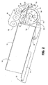
- the angular timing arrangement produces sensor transitions at specific points of system control activity such as "head fully lifted”, “tray support fully lifted” and “feed head fully pivoting” as respectively shown in Figs. 1 , 3 and 2 .
- the foregoing allows sensors 73 and 74 to sense the position of cam surfaces 76 and 77.
- Fig. 3 shows the feed system 9 in the configuration of an empty tray.
- the paper support 21 is lifted by the paper lift arm 51 and the paper support 21 rotates about the axis 22 until all of the sheets in the stack 14 ( Fig. 1 ) have been depleted.
- the paper support 21 has advanced to a maximum counter clockwise position and the feed head 60 comes to rest at a maximum counter clockwise position the full capacity of the feed system 9 is utilized.
- the total angular movement A of paper support 21 with respect to the base 20 of tray assembly 11 is between 0 degrees and 60 degrees with a typical angular motion of 0 degrees to 25 degrees.
- the feed head 60 undergoes a similar angular displacement B between 0 degrees and 50 degrees with a typical angular motion between 0 degrees and 20 degrees.
Landscapes
- Engineering & Computer Science (AREA)
- Mechanical Engineering (AREA)
- Sheets, Magazines, And Separation Thereof (AREA)
Claims (15)
- Dispositif pour délivrer des feuilles, le dispositif comprenant :un ensemble de plateau (11, 12) pour contenir des feuilles, les feuilles reposant sur un support pivotant (21) ;un ensemble d'alimentation (9, 10) pour séparer les feuilles, l'ensemble d'alimentation étant agencé de façon à pivoter sur un axe (61) parallèle à l'axe de pivot du support pivotant (21) ; caractérisé par :un mécanisme de liaison (51, 77) qui couple un mouvement de pivotement du support pivotant (21) à un mouvement de pivotement de l'ensemble d'alimentation (9, 10), de telle sorte que des feuilles puissent être présentées par le support pivotant à l'ensemble d'alimentation.
- Dispositif selon la revendication 1, dans lequel l'ensemble d'alimentation (9, 10) est agencé de façon à séparer des feuilles jusqu'à ce que la capacité autorisée par son mouvement de pivotement ait été épuisée, et à délivrer un signal de demande afin de déclencher le fonctionnement du mécanisme de liaison (51, 77), de façon à provoquer le pivotement du support pivotant, et à élever les feuilles en conséquence, et, par conséquent, l'ensemble d'alimentation (9, 10), afin de déclencher une autre séparation de feuilles par l'ensemble d'alimentation.
- Dispositif selon la revendication 1 ou 2, dans lequel la majeure partie du mécanisme d'élévation (51, 77) est constituée à une extrémité dudit ensemble de plateau d'alimentation (11, 12).
- Dispositif selon l'une quelconque des revendications précédentes, dans lequel le support pivotant (21) est agencé de façon à pivoter d'un angle compris entre zéro degré et soixante degrés.
- Dispositif selon l'une quelconque des revendications précédentes, dans lequel l'ensemble de plateau (11, 12) comprend :un plateau comportant une extrémité d'alimentation en feuilles et une extrémité de chargement de plateau ; une base (20) ; et un capot fixe (25) qui est en pente vers le bas de l'extrémité d'alimentation de plateau (16) à l'extrémité de chargement de plateau (17).
- Dispositif selon l'une quelconque des revendications précédentes, dans lequel le mécanisme de liaison comprend :un bras d'élévation monté de façon à pouvoir pivoter (51) agencé de façon à élever le plateau ;une première came de bras d'élévation (76) ;un premier galet de came (54) reliant le bras d'élévation à la première came ; etun moteur agencé de façon à entraîner la première came.
- Dispositif selon la revendication 6, dans lequel le mécanisme de liaison comprend de plues :une deuxième came (7.7) agencée de façon à élever l'ensemble d'alimentation (9, 10) ;un deuxième galet de came (82) reliant l'ensemble d'alimentation à la deuxième came, de telle sorte que le moteur entraîne la deuxième came.
- Dispositif selon la revendication 2 ou l'une quelconque des revendications 3 à 7 dépendant de la revendication 2, dans lequel le mécanisme de liaison comprend de plus :un capteur (63) agencé de façon à détecter l'angle de l'ensemble d'alimentation autour de son axe (61), et, par conséquent, à provoquer le déclenchement du fonctionnement du mécanisme de liaison en réponse à la réalisation d'un certain nombre de séparations de feuilles successives, et son arrêt lorsque l'ensemble d'alimentation (9, 10) est élevé.
- Dispositif selon l'une quelconque des revendications précédentes, dans lequel le mécanisme de liaison comprend de plus :un capteur (74) agencé de façon à détecter la position de la première came (76), pour produire une transition de capteur lorsque le support pivotant (21) est dans une position totalement élevée.
- Dispositif selon la revendication 5, dans lequel le mécanisme de liaison comprend de plus :un capteur (73) agencé de façon à détecter la position de la deuxième came (77), pour produire une transition de capteur lorsque l'ensemble d'alimentation (9, 10) est dans une position totalement élevée.
- Dispositif selon l'une quelconque des revendications précédentes, dans lequel le mécanisme de liaison comprend de plus :un capteur (73) agencé de façon à détecter la position de la deuxième came (77), pour produire une transition de capteur lorsque l'ensemble d'alimentation (9, 10) est dans une position totalement pivotée.
- Dispositif selon l'une quelconque des revendications 1 à 4, dans lequel l'ensemble de plateau comprend de plus :un plateau comportant une extrémité d'alimentation en feuilles (16) et une extrémité de chargement d'alimentation en feuilles (17) ; une base (20) ; et des parois latérales réglables reliées à la base (20), les parois latérales réglables couvrant moins de la moitié de la longueur du plateau, de telle sorte que des feuilles puissent être chargées dans le plateau.
- Dispositif selon l'une quelconque des revendications 1 à 4, dans lequel les parois latérales réglables du plateau sont en pente vers le bas de l'extrémité d'alimentation en feuilles (16) à l'extrémité de chargement d'alimentation en feuilles (17).
- Dispositif selon l'une quelconque des revendications précédentes, dans lequel le support de feuilles pivotant (21) peut être abaissé de façon à permettre aux feuilles d'être chargées dans l'ensemble de plateau (11, 12).
- Dispositif selon la revendication 10, dans lequel l'ensemble d'alimentation (9, 10) est monté de façon à pouvoir être élevé afin de permettre aux feuilles d'être chargées dans l'ensemble de plateau (11, 12).
Applications Claiming Priority (2)
| Application Number | Priority Date | Filing Date | Title |
|---|---|---|---|
| US79569006P | 2006-04-28 | 2006-04-28 | |
| PCT/US2007/010302 WO2007127405A2 (fr) | 2006-04-28 | 2007-04-26 | Procede permettant de placer un grand volume de feuilles dans un mecanisme alimentateur |
Publications (3)
| Publication Number | Publication Date |
|---|---|
| EP2013124A2 EP2013124A2 (fr) | 2009-01-14 |
| EP2013124A4 EP2013124A4 (fr) | 2012-06-27 |
| EP2013124B1 true EP2013124B1 (fr) | 2014-11-05 |
Family
ID=38656228
Family Applications (1)
| Application Number | Title | Priority Date | Filing Date |
|---|---|---|---|
| EP07776392.8A Active EP2013124B1 (fr) | 2006-04-28 | 2007-04-26 | Dispositif pour alimenter de feuilles dans un mecanisme alimentateur |
Country Status (3)
| Country | Link |
|---|---|
| US (1) | US7753364B2 (fr) |
| EP (1) | EP2013124B1 (fr) |
| WO (1) | WO2007127405A2 (fr) |
Families Citing this family (2)
| Publication number | Priority date | Publication date | Assignee | Title |
|---|---|---|---|---|
| US8016282B2 (en) * | 2007-12-21 | 2011-09-13 | Pitney Bowes Inc. | Transport for singulating items |
| JP2009286517A (ja) * | 2008-05-27 | 2009-12-10 | Kyocera Mita Corp | 給紙装置及びこれを搭載した原稿搬送装置、画像形成装置 |
Family Cites Families (7)
| Publication number | Priority date | Publication date | Assignee | Title |
|---|---|---|---|---|
| US4319740A (en) * | 1980-06-23 | 1982-03-16 | Minnesota Mining And Manufacturing Company | Sheet feeder |
| US4667949A (en) * | 1983-05-26 | 1987-05-26 | Am International, Inc. | Sheet stacking device |
| JPH0829846B2 (ja) * | 1989-05-09 | 1996-03-27 | シャープ株式会社 | 給紙装置 |
| JP3116448B2 (ja) * | 1991-09-13 | 2000-12-11 | ブラザー工業株式会社 | 給紙カセット |
| JPH0986705A (ja) * | 1995-07-18 | 1997-03-31 | Mitsubishi Electric Corp | 自動給紙装置 |
| JP3661783B2 (ja) * | 2001-10-15 | 2005-06-22 | ニスカ株式会社 | 原稿給紙装置及び原稿給紙制御方法 |
| JP2004001928A (ja) * | 2002-05-30 | 2004-01-08 | Sharp Corp | シート体供給搬送装置 |
-
2007
- 2007-04-13 US US11/786,877 patent/US7753364B2/en active Active
- 2007-04-26 WO PCT/US2007/010302 patent/WO2007127405A2/fr not_active Ceased
- 2007-04-26 EP EP07776392.8A patent/EP2013124B1/fr active Active
Also Published As
| Publication number | Publication date |
|---|---|
| US20070284807A1 (en) | 2007-12-13 |
| WO2007127405A3 (fr) | 2008-10-02 |
| WO2007127405A2 (fr) | 2007-11-08 |
| US7753364B2 (en) | 2010-07-13 |
| EP2013124A2 (fr) | 2009-01-14 |
| EP2013124A4 (fr) | 2012-06-27 |
Similar Documents
| Publication | Publication Date | Title |
|---|---|---|
| US7699303B2 (en) | Multimode stack and shingle document feeder | |
| US20040032077A1 (en) | Passive media separating device | |
| US8417174B2 (en) | Sheet feeding device and image forming apparatus incorporating same | |
| JP2004075395A (ja) | 印刷機の用紙重送防止装置 | |
| US6824131B2 (en) | Method and apparatus for image forming and effectively performing sheet feeding using a sheet feed roller and a tilt member | |
| KR100293739B1 (ko) | 프린터의급지장치 | |
| JP3680312B2 (ja) | 給紙装置 | |
| EP2013124B1 (fr) | Dispositif pour alimenter de feuilles dans un mecanisme alimentateur | |
| JPH11217132A (ja) | 自動給紙装置 | |
| WO2003042081A2 (fr) | Separateur articule | |
| EP0681973A1 (fr) | Dispositif de saisie préliminaire pour un méchanisme de saisie d'une copie | |
| US7946574B2 (en) | Sheet material feeder | |
| JPH04182251A (ja) | 紙葉類堆積装置 | |
| US8262081B2 (en) | Trail edge guide deflector for improved media feeding | |
| JPH0275535A (ja) | カセットケースを用いる給紙装置 | |
| US7029005B2 (en) | Media positioning at a picking location | |
| JPH07196186A (ja) | シート材給送装置 | |
| CN2719785Y (zh) | 可动态调整取纸角度的纸张传送机构 | |
| US7316391B2 (en) | Automated paper stack conditioning | |
| EP2620399B1 (fr) | Sélecteur de courrier articulé | |
| EP1783076A2 (fr) | Dispositif pour l'alimentation de produits supports d'information en formation imbriquée | |
| KR100449108B1 (ko) | 인쇄기기의 급지장치 | |
| JP2975856B2 (ja) | 自動給紙方法及び装置 | |
| JP2000264467A (ja) | 給紙装置 | |
| JP2005263497A (ja) | シート供給装置及びこれに用いられるエンドガイド |
Legal Events
| Date | Code | Title | Description |
|---|---|---|---|
| PUAI | Public reference made under article 153(3) epc to a published international application that has entered the european phase |
Free format text: ORIGINAL CODE: 0009012 |
|
| 17P | Request for examination filed |
Effective date: 20080917 |
|
| AK | Designated contracting states |
Kind code of ref document: A2 Designated state(s): AT BE BG CH CY CZ DE DK EE ES FI FR GB GR HU IE IS IT LI LT LU LV MC MT NL PL PT RO SE SI SK TR |
|
| AX | Request for extension of the european patent |
Extension state: AL BA HR MK RS |
|
| RIC1 | Information provided on ipc code assigned before grant |
Ipc: B65H 1/00 20060101AFI20090123BHEP Ipc: B65H 3/06 20060101ALI20090123BHEP |
|
| DAX | Request for extension of the european patent (deleted) | ||
| RBV | Designated contracting states (corrected) |
Designated state(s): DE FR GB |
|
| REG | Reference to a national code |
Ref country code: DE Ref legal event code: R079 Ref document number: 602007039155 Country of ref document: DE Free format text: PREVIOUS MAIN CLASS: B65H0001000000 Ipc: B65H0001140000 |
|
| A4 | Supplementary search report drawn up and despatched |
Effective date: 20120530 |
|
| RIC1 | Information provided on ipc code assigned before grant |
Ipc: B65H 3/06 20060101ALI20120523BHEP Ipc: B65H 1/14 20060101AFI20120523BHEP |
|
| GRAP | Despatch of communication of intention to grant a patent |
Free format text: ORIGINAL CODE: EPIDOSNIGR1 |
|
| INTG | Intention to grant announced |
Effective date: 20140526 |
|
| GRAS | Grant fee paid |
Free format text: ORIGINAL CODE: EPIDOSNIGR3 |
|
| GRAA | (expected) grant |
Free format text: ORIGINAL CODE: 0009210 |
|
| AK | Designated contracting states |
Kind code of ref document: B1 Designated state(s): DE FR GB |
|
| REG | Reference to a national code |
Ref country code: GB Ref legal event code: FG4D |
|
| REG | Reference to a national code |
Ref country code: DE Ref legal event code: R096 Ref document number: 602007039155 Country of ref document: DE Effective date: 20141218 |
|
| REG | Reference to a national code |
Ref country code: DE Ref legal event code: R097 Ref document number: 602007039155 Country of ref document: DE |
|
| PLBE | No opposition filed within time limit |
Free format text: ORIGINAL CODE: 0009261 |
|
| STAA | Information on the status of an ep patent application or granted ep patent |
Free format text: STATUS: NO OPPOSITION FILED WITHIN TIME LIMIT |
|
| 26N | No opposition filed |
Effective date: 20150806 |
|
| REG | Reference to a national code |
Ref country code: FR Ref legal event code: PLFP Year of fee payment: 10 |
|
| REG | Reference to a national code |
Ref country code: FR Ref legal event code: PLFP Year of fee payment: 11 |
|
| REG | Reference to a national code |
Ref country code: FR Ref legal event code: PLFP Year of fee payment: 12 |
|
| P01 | Opt-out of the competence of the unified patent court (upc) registered |
Effective date: 20230408 |
|
| PGFP | Annual fee paid to national office [announced via postgrant information from national office to epo] |
Ref country code: DE Payment date: 20250429 Year of fee payment: 19 |
|
| PGFP | Annual fee paid to national office [announced via postgrant information from national office to epo] |
Ref country code: GB Payment date: 20250428 Year of fee payment: 19 |
|
| PGFP | Annual fee paid to national office [announced via postgrant information from national office to epo] |
Ref country code: FR Payment date: 20250425 Year of fee payment: 19 |