EP2013517B1 - Dispositif de commande et boîte de vitesses - Google Patents
Dispositif de commande et boîte de vitesses Download PDFInfo
- Publication number
- EP2013517B1 EP2013517B1 EP07748395A EP07748395A EP2013517B1 EP 2013517 B1 EP2013517 B1 EP 2013517B1 EP 07748395 A EP07748395 A EP 07748395A EP 07748395 A EP07748395 A EP 07748395A EP 2013517 B1 EP2013517 B1 EP 2013517B1
- Authority
- EP
- European Patent Office
- Prior art keywords
- locking
- control rod
- control device
- recess
- locking means
- Prior art date
- Legal status (The legal status is an assumption and is not a legal conclusion. Google has not performed a legal analysis and makes no representation as to the accuracy of the status listed.)
- Not-in-force
Links
- 230000009471 action Effects 0.000 claims abstract description 12
- 230000004044 response Effects 0.000 claims description 5
- 230000008901 benefit Effects 0.000 description 9
- 230000008859 change Effects 0.000 description 2
- 230000000694 effects Effects 0.000 description 2
- 229910000831 Steel Inorganic materials 0.000 description 1
- 238000010276 construction Methods 0.000 description 1
- 230000001419 dependent effect Effects 0.000 description 1
- 230000005489 elastic deformation Effects 0.000 description 1
- 230000006870 function Effects 0.000 description 1
- 238000004519 manufacturing process Methods 0.000 description 1
- 230000007246 mechanism Effects 0.000 description 1
- 239000002184 metal Substances 0.000 description 1
- 230000004048 modification Effects 0.000 description 1
- 238000012986 modification Methods 0.000 description 1
- 230000007935 neutral effect Effects 0.000 description 1
- 230000008447 perception Effects 0.000 description 1
- 238000009877 rendering Methods 0.000 description 1
- 239000010959 steel Substances 0.000 description 1
Images

Classifications
-
- F—MECHANICAL ENGINEERING; LIGHTING; HEATING; WEAPONS; BLASTING
- F16—ENGINEERING ELEMENTS AND UNITS; GENERAL MEASURES FOR PRODUCING AND MAINTAINING EFFECTIVE FUNCTIONING OF MACHINES OR INSTALLATIONS; THERMAL INSULATION IN GENERAL
- F16H—GEARING
- F16H63/00—Control outputs from the control unit to change-speed- or reversing-gearings for conveying rotary motion or to other devices than the final output mechanism
- F16H63/02—Final output mechanisms therefor; Actuating means for the final output mechanisms
- F16H63/30—Constructional features of the final output mechanisms
-
- F—MECHANICAL ENGINEERING; LIGHTING; HEATING; WEAPONS; BLASTING
- F16—ENGINEERING ELEMENTS AND UNITS; GENERAL MEASURES FOR PRODUCING AND MAINTAINING EFFECTIVE FUNCTIONING OF MACHINES OR INSTALLATIONS; THERMAL INSULATION IN GENERAL
- F16H—GEARING
- F16H63/00—Control outputs from the control unit to change-speed- or reversing-gearings for conveying rotary motion or to other devices than the final output mechanism
- F16H63/02—Final output mechanisms therefor; Actuating means for the final output mechanisms
- F16H63/30—Constructional features of the final output mechanisms
- F16H63/38—Detents
-
- G—PHYSICS
- G05—CONTROLLING; REGULATING
- G05G—CONTROL DEVICES OR SYSTEMS INSOFAR AS CHARACTERISED BY MECHANICAL FEATURES ONLY
- G05G5/00—Means for preventing, limiting or returning the movements of parts of a control mechanism, e.g. locking controlling member
- G05G5/06—Means for preventing, limiting or returning the movements of parts of a control mechanism, e.g. locking controlling member for holding members in one or a limited number of definite positions only
-
- F—MECHANICAL ENGINEERING; LIGHTING; HEATING; WEAPONS; BLASTING
- F16—ENGINEERING ELEMENTS AND UNITS; GENERAL MEASURES FOR PRODUCING AND MAINTAINING EFFECTIVE FUNCTIONING OF MACHINES OR INSTALLATIONS; THERMAL INSULATION IN GENERAL
- F16H—GEARING
- F16H63/00—Control outputs from the control unit to change-speed- or reversing-gearings for conveying rotary motion or to other devices than the final output mechanism
- F16H63/02—Final output mechanisms therefor; Actuating means for the final output mechanisms
- F16H63/30—Constructional features of the final output mechanisms
- F16H2063/3079—Shift rod assembly, e.g. supporting, assembly or manufacturing of shift rails or rods; Special details thereof
-
- Y—GENERAL TAGGING OF NEW TECHNOLOGICAL DEVELOPMENTS; GENERAL TAGGING OF CROSS-SECTIONAL TECHNOLOGIES SPANNING OVER SEVERAL SECTIONS OF THE IPC; TECHNICAL SUBJECTS COVERED BY FORMER USPC CROSS-REFERENCE ART COLLECTIONS [XRACs] AND DIGESTS
- Y10—TECHNICAL SUBJECTS COVERED BY FORMER USPC
- Y10T—TECHNICAL SUBJECTS COVERED BY FORMER US CLASSIFICATION
- Y10T74/00—Machine element or mechanism
- Y10T74/20—Control lever and linkage systems
- Y10T74/20012—Multiple controlled elements
- Y10T74/20018—Transmission control
- Y10T74/20085—Restriction of shift, gear selection, or gear engagement
- Y10T74/20104—Shift element interlock
- Y10T74/20116—Resiliently biased interlock
-
- Y—GENERAL TAGGING OF NEW TECHNOLOGICAL DEVELOPMENTS; GENERAL TAGGING OF CROSS-SECTIONAL TECHNOLOGIES SPANNING OVER SEVERAL SECTIONS OF THE IPC; TECHNICAL SUBJECTS COVERED BY FORMER USPC CROSS-REFERENCE ART COLLECTIONS [XRACs] AND DIGESTS
- Y10—TECHNICAL SUBJECTS COVERED BY FORMER USPC
- Y10T—TECHNICAL SUBJECTS COVERED BY FORMER US CLASSIFICATION
- Y10T74/00—Machine element or mechanism
- Y10T74/20—Control lever and linkage systems
- Y10T74/20012—Multiple controlled elements
- Y10T74/20018—Transmission control
- Y10T74/20085—Restriction of shift, gear selection, or gear engagement
- Y10T74/20128—Resiliently biased restrictor
Definitions
- the present invention relates to a control device according to the preamble of claim 1 and a gearbox comprising such a control device.
- DE-A-100 64 609 represents the closest prior art to the subject-matter of independent claim 1.
- a manual gearbox of a motor vehicle e.g. a passenger car, a truck, a tractor vehicle for semitrailers or a bus
- the engagement of desired gears is usually controlled by a control device which forms part of the gearbox and is provided with a plurality of control rods.
- These control rods can, by operation of the vehicle's gear lever, be moved between various predetermined setting positions which define the various gear positions of the gearbox.
- Each control rod cooperates with a locking arrangement which ensures that the control rod will assume one of the predetermined setting positions in response to movement of the gear lever and that the control rod is not unintentionally shifted from the relevant setting position.
- EP 0 702 172 A1 refers to a conventional type of locking arrangement for a control rod of a gearbox.
- This locking arrangement comprises a locking means which, through the action of a spring means, is adapted to engaging in various recesses of the control rod. Each of these recesses corresponds to a predetermined setting position of the control rod. Each recess has a guide surface adapted to cooperating with the locking means in such a way that the locking means, through the action of this guide surface and against the action of the spring means, will move from a protruded position to a retracted position in response to an axial movement of the control rod starting from a setting position of the control rod with the locking means engaged in the respective recess.
- the object of the invention is to provide a further development of a control device of the type indicated above in order to propose a configuration which in at least some respects affords an advantage as compared with a conventionally configured control device.
- the control device comprises at least one control rod with a relating locking arrangement, which locking arrangement comprises a locking element provided with one or more grooves or recesses which each define a predetermined setting position of the control rod, whereby the control rod is arranged for movement relative to the locking element.
- the locking arrangement further comprises a resilient locking means arranged in a recess in the control rod, which locking means has a locking portion which, against the action of a spring force of the locking means, is arranged for movement in said recess in the control rod's radial direction between a protruded position in which the locking portion engages in one of said grooves/recesses in the locking element and thereby counteracts movement of the control rod relative to the locking element, and a retracted position in which the locking portion does not engage in any of said grooves/recesses in the locking element.
- the locking means takes the form of a leaf spring, making it possible for the locking means to be manufactured easily and at low cost.
- the locking means is thus arranged in the actual control rod, thereby rendering the locking arrangement particularly space-saving.
- the solution according to the invention also makes simplified construction of the control device possible as compared with the conventional solution described above, thus providing the possibility of reduced manufacturing costs.
- the locking arrangement need not comprise any separate spring means acting upon the locking means, since the locking means is inherently resilient.
- the locking means sits loosely in the relating recess in the control rod, with the advantageous result that the locking means, by abutment against side surfaces of the relating recess in the control rod, is prevented from moving in the control rod's longitudinal direction and circumferential direction.
- the need for special fastening means for fitting the locking means in the control rod's recess is thus eliminated, making it possible for the locking arrangement to comprise a small number of components of simple configuration and at the same time to be particularly easy to fit.
- the invention also relates to a gearbox, preferably in the form of a manual gearbox for a motor vehicle, comprising a control device according to the present invention.
- the control device 1 is intended to form part of a gearbox in order to control the engagement of desired gears of the gearbox.
- the control device and the relating gearbox may be of conventional and known configuration.
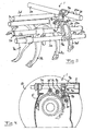
- Figs. 1 and 3 illustrate four control rods 3a-3d arranged for linear movement in a holder unit 2 and forming part of a control device 1 according to the present invention.
- the holder unit is omitted for the sake of clarity.
- the number of control rods of the control device according to the invention may be both larger or smaller than here illustrated.
- the holder unit 2 may be integrated in the housing 5 of the relating gearbox, as schematically illustrated in Fig. 1 .
- Each control rod 3a-3d is supported for movement relative to the holder unit 2 in such a way that relative to the holder unit it is movable in its longitudinal direction.
- Each control rod 3a-3d may be supported relative to the holder unit 2 via, for example, a plain bearing 6a, 6b at each end of the control rod, as illustrated in Fig. 1 .
- Each control rod 3a-3d is connected in a known manner to a gear lever by means of which the control rod 3a-3d can be caused to move relative to the holder unit 2.
- the gear lever By operating the gear lever between various predetermined positions, the user, e.g. a driver in a motor vehicle, can place the control rods 3a-3d in desired setting positions relative to the holder unit 2.
- Each control rod 3a-3d effects in a known manner not here described, via a selector fork 7a-7d, the engagement and disengagement of various predetermined gears of the gearbox.
- Each selector fork 7a-7d moves together with the relating control rod 3a-3d and acts upon the gear position of the gearbox via a known and not here illustrated control mechanism of the gearbox.
- Each control rod effects the engagement and disengagement of two different gears of the gearbox. From a neutral position, each control rod 3a-3d can be moved longitudinally in one direction to a predetermined setting position to engage a first of said two gears and in another direction to another predetermined setting position to engage the second of said two gears.
- control rods 3a-3c in the example illustrated are connected to a common control rod 3e, hereinafter called the operating rod.
- the operating rod 3e is supported for linear and rotary movement relative to the holder unit 2 in such a way that relative to the holder unit it is movable in its longitudinal direction and rotatable about its longitudinal axis.
- the operating rod 3e is connected in a known manner not here illustrated to a gear lever by means of which the operating rod 3e can be caused to perform linear and rotary movements relative to the holder unit 2.
- a driver in a motor vehicle can move the operating rod 3e in its longitudinal direction and place it in any of a plurality predetermined linear positions.
- the operating rod 3e has a predetermined linear position.
- the operating rod 3e is adapted to being able to move one control rod 3a-3c at a time between these predetermined setting positions by being rotated in a desired direction about its longitudinal axis.
- the control rods 3a-3c are each provided with control means 9a-9c for cooperation with a corresponding control means 9e of the operating rod 3e.
- Each control means 9a-9c, 9e is firmly connected to the relating rod 3a-3c, 3e.
- the control means 9e is thus caused to perform linear and rotary movements together with the operating rod 3 e, and each control means 9a-9c will move together with the relating control rod 3a-3c.
- each control means 9a-9c will move together with the relating control rod 3a-3c.
- its control means 9e can be brought into engagement with one at a time of the control means 9a-9c of the control rods 3a-3c.
- rotary motion of the operating rod 3e is converted to axial linear movement of the respective control rod via mutual engagement between the operating rod's control means 9e and the control rod's control means 9a-9c.
- the setting position of the fourth control rod 3d is in the example illustrated not controlled by the operating rod 3e but may, for example, be adapted to being controlled pneumatically in a conventional manner not further described here.
- Each of the control device's control rods 3a-3d is allocated a locking arrangement 20 adapted to defining one or more predetermined setting positions of the control rod 3a-3d relative to the holder unit 2.
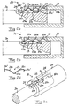
- Figs. 2a-2c depict part of a control rod 3a with such a locking arrangement 20.
- the locking arrangement 20 comprises a locking element 21 provided with one or more grooves or recesses 22a-22c which each define a predetermined setting position of the control rod 3a relative to the holder unit 2.
- Each groove/recess 22a-22c faces towards the control rod 3a.
- the locking arrangement 20 is arranged to define three different setting positions of the control rod 3a relative to the holder unit 2, and in this case the locking arrangement is provided with three grooves/recesses 22a-22c arranged in line consecutively in a direction parallel with the control rod's longitudinal axis.
- the control rod 3a is arranged for movement relative to the locking element 21.
- the locking element 21 is with advantage arranged in a bearing 6a which is one of the bearings via which the control rod 3a is fastened to the holder unit 2.
- the locking element 21 takes the form of a separate plate provided at one of its ends with said grooves 22a-22c and fitted in a slit 28 in a sleeve 29.
- the sleeve 29 has an internal bore 29a in which part of the control rod 3a is slidably accommodated.
- the locking element 21 might be integrated in a sleeve 29 of the type illustrated with respective grooves/recesses 22a-22c formed internally in the sleeve's bore 29a.
- Other embodiments of the locking element are of course also conceivable.
- the locking arrangement 20 further comprises a resilient locking means 23 arranged in a recess 24 in the control rod 3a.
- This recess 24 is arranged in the control rod's shell surface.
- the locking means has a locking portion 23a which, against the action of a spring force of the locking means 23, is arranged for movement in said recess 24 in the control rod's radial direction between a protruded position (see Fig. 2a ) in which the locking portion 23a engages in one of said grooves/recesses 22a-22c in the locking element and thereby counteracts linear movement of the control rod 3a relative to the locking element 21 and the holder unit 2, and a retracted position (see Fig.
- the locking portion 23a has with advantage a convex shape in side view, as illustrated in Figs. 2a and 2b .
- the locking means 23 is elastically deformable and undergoes elastic deformation when the locking portion 23a moves from the protruded position to the retracted position, as illustrated by Figs. 2a and 2b . When thereafter the locking portion 23a reverts to the protruded position, the locking means 23 springs back and resumes its original shape.
- the locking means 23 has two support portions 23b, 23c which are arranged on opposite sides of the locking portion 23a and support the locking portion 23a and via which the locking means 23 abuts against surfaces of the relating recess 24 in the control rod. These support portions 23b, 23c constitute limbs of the locking means 23 which connect to the locking portion 23a situated between them. In the example illustrated, the support portions 23b, 23c rest against a bottom surface 24a of the recess 24.
- the contact surfaces between the control rod 3 a and the support portions 23b, 23c of the locking means constitute mutual slide surfaces which allow mutual sliding between the support portions and the control rod in the control rod's axial direction in response to a change of shape of the locking means 23 when its locking portion 23a moves in either direction between the protruded position and the retracted position.
- the end directed away from the locking portion 23a of each support portion 23b, 23c in the example illustrated is bent towards the locking portion 23a (upwards in the side view according to Fig. 2a and downwards in the side view according to Fig. 2d ) to form a hooklike end section 23b', 23c'.
- the hooklike end sections 23b', 23c' thus point in the same direction as the locking portion 23a.
- the hooklike end sections 23b', 23c' are fully accommodated in the recess 24 and each has its outside abutting against the adjacent side surface 24b, 24c at its respective opposite axial end of the recess 24.
- the locking means 23 is preferably gullwing-shaped in side view with the locking portion 23a facing downwards, as illustrated in Fig. 2d .
- the locking means 23 might nevertheless also be of some other suitable shape.
- the locking means 23 is advantageously made of metal, preferably steel, and takes with advantage the form of a leaf spring.
- the locking means 23 with advantage sits loosely in the relating recess 24 in the control rod and is with advantage prevented from moving in the control rod's longitudinal direction and circumferential direction by abutting against side surfaces of the relating recess 24 in the control rod.
- the locking means 23 and the relating recess 24 in the control rod are with advantage elongate and arranged to extend in the control rod's longitudinal direction, as illustrated in Figs. 2a-2c .
- the control rod 3a To change from one setting position to another, the control rod 3a has to be moved in its longitudinal direction with such force that the spring force of the locking means 23 is overcome and the locking portion 23a of the locking means is brought out of engagement with the respective groove/recess of the locking element.
- the locking portion 23a will, through the action of the spring force of the locking means 23, move forward to engage with that groove/recess and thereby counteract further movement of the control rod.
- Each groove/recess 22a-22c in the locking element has a guide surface 27 adapted to cooperating with the locking portion 23a of the locking means in such a way that the locking portion will, through the action of this guide surface, move from its protruded position to its retracted position in response to a movement of the control rod 3 a relative to locking element 21 starting from a setting position of the control rod with the locking portion 23a in engagement with the respective groove/recess 22a-22c.
- the grooves/recesses 22a-22c together constitute with advantage a substantially sinusoidal profile as seen in longitudinal section through the locking element 21, as illustrated in Figs. 2a and 2b .
- the operating rod 3e is also allocated a locking arrangement of the type described above which defines various predetermined setting positions of the operating rod 3e relative to the holder unit 2.
- the control device 1 is particularly intended to form part of a manual gearbox for a motor vehicle. Part of such a gearbox 10 is illustrated schematically in Fig. 4 .
Landscapes
- Engineering & Computer Science (AREA)
- General Engineering & Computer Science (AREA)
- Mechanical Engineering (AREA)
- Physics & Mathematics (AREA)
- General Physics & Mathematics (AREA)
- Automation & Control Theory (AREA)
- Gear-Shifting Mechanisms (AREA)
- Structure Of Transmissions (AREA)
- Toys (AREA)
Claims (10)
- Dispositif de commande pour commander l'engagement des vitesses désirées d'une boîte de vitesses, lequel dispositif de commande (1) comprend une unité de support (2) et au moins une tige de commande (3a) dotée d'un agencement de verrouillage correspondant, la tige de commande (3a) étant disposée pour un effectuer mouvement linéaire dans l'unité de support (2), et l'agencement de verrouillage (20) correspondant étant destiné à définir une ou plusieurs positions de réglage prédéterminées de la tige de commande (3a) par rapport à l'unité de support (2), l'agencement de verrouillage (20) comprenant :- un élément de verrouillage (21) pourvu d'une ou plusieurs rainures ou évidements (22a-22c), chacun(e) définissant une position de réglage prédéterminée de la tige de commande (3a) par rapport à l'unité de support (2), la tige de commande (3a) étant agencée pour effectuer un mouvement linéaire par rapport à l'élément de verrouillage (21); et- un moyen de verrouillage élastique (23) disposé dans un évidement (24) ménagé dans la tige de commande, ledit moyen de verrouillage (23) présentant une partie de verrouillage (23a) qui, s'opposant à l'action d'une force de ressort du moyen de verrouillage (23), est agencée pour se déplacer dans ledit évidement (24) dans la direction radiale de la tige de commande entre une position en saillie dans laquelle la partie de verrouillage (23a) s'engage dans l'un(e) desdit(e)s rainures/évidements (22a-22c) ménagé(e)s dans l'élément de verrouillage et s'oppose ainsi au mouvement de la tige de commande par rapport à l'élément de verrouillage, et une position rétractée dans laquelle la partie de verrouillage (23a) ne s'engage pas dans l'un(e) quelconque desdit(e)s rainures/évidements dans l'élément de verrouillage,caractérisé en ce que le moyen de verrouillage (23) prend la forme d'un ressort à lames.
- Dispositif de commande selon la revendication 1, caractérisé en ce que le moyen de verrouillage (23) et l'évidement correspondant (24) dans la tige de commande sont de forme allongée et agencés pour s'étendre dans la direction longitudinale de la tige de commande.
- Dispositif de commande selon la revendication 1-2, caractérisé en ce que le moyen de verrouillage (23) présente deux parties support (23b, 23c) qui sont disposées sur des côtés opposés de la partie de verrouillage (23a) et supportent la partie de verrouillage (23a) et par l'intermédiaire desquelles le moyen de verrouillage (23) est en appui contre des surfaces de l'évidement (24) correspondant dans la tige de commande.
- Dispositif de commande selon la revendication 3, caractérisé en ce que l'extrémité opposée à la partie de verrouillage (23a) de chaque partie support (23b, 23c) est incurvée pour former une section d'extrémité en forme de crochet (23b'-23c').
- Dispositif de commande selon l'une quelconque des revendications 1 à 4, caractérisé en ce que le moyen de verrouillage (23) est en forme d'ailes de goéland en vue de côté, la partie de verrouillage (23a) étant tournée vers le bas.
- Dispositif de commande selon l'une quelconque des revendications 1 à 5, caractérisé en ce que le moyen de verrouillage (23) repose librement dans l'évidement (24) correspondant ménagé dans la tige de commande.
- Dispositif de commande selon la revendication 6, caractérisé en ce que le moyen de verrouillage (23), en venant en appui contre des surfaces latérales de l'évidement (24) correspondant dans la tige de commande, est empêché de se déplacer dans la direction longitudinale et dans la direction circonférentielle de la tige de commande.
- Dispositif de commande selon l'une quelconque des revendications 1 à 7, caractérisé en ce que la partie de verrouillage (23a) a une forme convexe, vue de côté.
- Dispositif de commande selon l'une quelconque des revendications 1 à 8, caractérisé en ce que chaque rainure/évidement (22a-22c) dans la tige de commande présente une surface de guidage (27) agencée pour coopérer avec la partie de verrouillage (23a) du moyen de verrouillage de manière telle que la partie de verrouillage (23a), par le biais de l'action de cette surface de guidage, se déplacera de sa position en saillie vers sa position rétractée en réponse à un mouvement de la tige de commande (3a) par rapport à l'élément de verrouillage (21) à partir d'une position de réglage de la tige de commande, la partie de verrouillage (23a) étant en prise dans la rainure/évidement (22a-22c) respectif.
- Boîte de vitesses, de préférence ayant la forme d'une boîte de vitesses manuelle pour un véhicule à moteur, caractérisé en ce qu'elle comprend un dispositif de commande (1) selon l'une quelconque des revendications 1 à 9.
Applications Claiming Priority (2)
| Application Number | Priority Date | Filing Date | Title |
|---|---|---|---|
| SE0600905A SE0600905L (fr) | 2006-04-26 | ||
| PCT/SE2007/050234 WO2007123478A1 (fr) | 2006-04-26 | 2007-04-11 | Dispositif de commande et boîte de vitesses |
Publications (2)
| Publication Number | Publication Date |
|---|---|
| EP2013517A1 EP2013517A1 (fr) | 2009-01-14 |
| EP2013517B1 true EP2013517B1 (fr) | 2010-08-18 |
Family
ID=38625285
Family Applications (1)
| Application Number | Title | Priority Date | Filing Date |
|---|---|---|---|
| EP07748395A Not-in-force EP2013517B1 (fr) | 2006-04-26 | 2007-04-11 | Dispositif de commande et boîte de vitesses |
Country Status (9)
| Country | Link |
|---|---|
| US (1) | US7963187B2 (fr) |
| EP (1) | EP2013517B1 (fr) |
| JP (1) | JP4781465B2 (fr) |
| KR (1) | KR20080111159A (fr) |
| CN (1) | CN101427057B (fr) |
| AT (1) | ATE478288T1 (fr) |
| BR (1) | BRPI0710277A2 (fr) |
| DE (1) | DE602007008551D1 (fr) |
| WO (1) | WO2007123478A1 (fr) |
Families Citing this family (8)
| Publication number | Priority date | Publication date | Assignee | Title |
|---|---|---|---|---|
| SE529864C2 (sv) * | 2006-05-03 | 2007-12-18 | Scania Cv Abp | Regleranordning och växellåda |
| DE102009041929A1 (de) * | 2009-09-17 | 2011-04-07 | Schaeffler Technologies Gmbh & Co. Kg | Schalteinheit |
| JP2012154450A (ja) * | 2011-01-27 | 2012-08-16 | Aisin Ai Co Ltd | 手動変速機の操作装置 |
| DE102013002684A1 (de) * | 2012-03-14 | 2013-09-19 | GM Global Technology Operations LLC (n. d. Gesetzen des Staates Delaware) | Innere Schaltbetätigung für ein Schaltgetriebe und Schaltgetriebe für ein Kraftfahrzeug |
| DE102012021261B4 (de) * | 2012-10-29 | 2019-02-14 | Trw Automotive Electronics & Components Gmbh | Betätigungsbaugruppe für ein Bedienelement, Lenkstockhebel sowie Lenkstockhebelbaugruppe |
| DE102013021963A1 (de) * | 2013-12-20 | 2015-06-25 | GM Global Technology Operations LLC (n. d. Ges. d. Staates Delaware) | Schaltgetriebe |
| EP3002485B1 (fr) * | 2014-10-03 | 2017-04-19 | Fiat Group Automobiles S.p.A. | Dispositif pour la sélection et le déplacement d'éléments d'actionnement d'une boîte de vitesses pour véhicules à moteur |
| CN110145597B (zh) * | 2019-06-05 | 2020-11-10 | 苏州东风精冲工程有限公司 | 适于拨叉空挡定位块与拨叉连接的结构及拔叉 |
Family Cites Families (11)
| Publication number | Priority date | Publication date | Assignee | Title |
|---|---|---|---|---|
| US4070914A (en) * | 1976-09-17 | 1978-01-31 | Jack Reinhardt | Hydraulic clutch-controlled transmission gear detent system |
| US4193316A (en) * | 1978-01-05 | 1980-03-18 | Borg-Warner Corporation | Transmission shift control mechanism |
| US4543846A (en) * | 1981-08-20 | 1985-10-01 | Toyota Jidosha Kabushiki Kaisha | Interlocking construction in transmission manipulation device for manual transmission |
| US4569247A (en) * | 1982-12-15 | 1986-02-11 | Toyota Jidosha Kabushiki Kaisha | Detent mechanism in manual transmission |
| JPS6228222U (fr) * | 1985-08-02 | 1987-02-20 | ||
| DE4019332C1 (fr) * | 1990-06-18 | 1991-07-11 | Ford-Werke Ag, 5000 Koeln, De | |
| JP3209010B2 (ja) | 1994-09-14 | 2001-09-17 | 三菱自動車工業株式会社 | 手動変速機の変速制御機構 |
| DE10014880A1 (de) * | 2000-03-24 | 2001-09-27 | Volkswagen Ag | Stufenwechselgetriebe |
| DE10064609A1 (de) * | 2000-12-22 | 2002-06-27 | Ina Schaeffler Kg | Schalteinrichtung eines Schaltgetriebes zum Wählen und Schalten von Gängen |
| JP3715209B2 (ja) * | 2001-02-13 | 2005-11-09 | 本田技研工業株式会社 | トランスミッション |
| DE10156392B4 (de) * | 2001-11-16 | 2008-04-10 | Robert Bosch Gmbh | Gangschaltvorrichtung für ein mehrstufiges Getriebe eines Elektrowerkzeugs |
-
2007
- 2007-04-11 WO PCT/SE2007/050234 patent/WO2007123478A1/fr not_active Ceased
- 2007-04-11 EP EP07748395A patent/EP2013517B1/fr not_active Not-in-force
- 2007-04-11 KR KR1020087028978A patent/KR20080111159A/ko not_active Ceased
- 2007-04-11 BR BRPI0710277-1A patent/BRPI0710277A2/pt not_active IP Right Cessation
- 2007-04-11 AT AT07748395T patent/ATE478288T1/de not_active IP Right Cessation
- 2007-04-11 DE DE602007008551T patent/DE602007008551D1/de active Active
- 2007-04-11 JP JP2009507640A patent/JP4781465B2/ja not_active Expired - Fee Related
- 2007-04-11 CN CN2007800146482A patent/CN101427057B/zh not_active Expired - Fee Related
- 2007-04-11 US US12/298,393 patent/US7963187B2/en not_active Expired - Fee Related
Also Published As
| Publication number | Publication date |
|---|---|
| US20090095107A1 (en) | 2009-04-16 |
| JP2009534620A (ja) | 2009-09-24 |
| CN101427057B (zh) | 2012-11-14 |
| CN101427057A (zh) | 2009-05-06 |
| KR20080111159A (ko) | 2008-12-22 |
| BRPI0710277A2 (pt) | 2011-08-09 |
| JP4781465B2 (ja) | 2011-09-28 |
| ATE478288T1 (de) | 2010-09-15 |
| US7963187B2 (en) | 2011-06-21 |
| WO2007123478A1 (fr) | 2007-11-01 |
| EP2013517A1 (fr) | 2009-01-14 |
| DE602007008551D1 (de) | 2010-09-30 |
Similar Documents
| Publication | Publication Date | Title |
|---|---|---|
| US7963187B2 (en) | Control arrangement and gearbox | |
| EP2010803B1 (fr) | Dispositif de commande et boîte de vitesses | |
| US7290800B2 (en) | Telescoping steering shaft | |
| EP2829457B1 (fr) | Coussinet de crémaillère | |
| EP2013518B1 (fr) | Dispositif de changement de vitesse et boite de vitesses | |
| JPH0235172B2 (ja) | Hensokukikudosochi | |
| US8408794B2 (en) | Linear ball bearing and supporting race element for the same | |
| JP4587066B2 (ja) | 変速機 | |
| EP3431317B1 (fr) | Dispositif de changement de vitesse | |
| EP1591696B1 (fr) | Levier de changement de vitesses pour une véhicule | |
| RU60035U1 (ru) | Механизм выбора передач коробки передач транспортного средства | |
| EP3124310B1 (fr) | Dispositif de levier | |
| KR100716554B1 (ko) | 수동변속기의 변속기구 | |
| DE102008052091A1 (de) | Schaltvorrichtung | |
| US20140083829A1 (en) | Actuator Assembly Having An External Plunger Sleeve | |
| KR19990015556U (ko) | 변속 레버의 리턴 스프링 지지 구조 | |
| CN102066784A (zh) | 线性滚动轴承和具有线性滚动轴承的换档装置 |
Legal Events
| Date | Code | Title | Description |
|---|---|---|---|
| PUAI | Public reference made under article 153(3) epc to a published international application that has entered the european phase |
Free format text: ORIGINAL CODE: 0009012 |
|
| 17P | Request for examination filed |
Effective date: 20081126 |
|
| AK | Designated contracting states |
Kind code of ref document: A1 Designated state(s): AT BE BG CH CY CZ DE DK EE ES FI FR GB GR HU IE IS IT LI LT LU LV MC MT NL PL PT RO SE SI SK TR |
|
| AX | Request for extension of the european patent |
Extension state: AL BA HR MK RS |
|
| RIN1 | Information on inventor provided before grant (corrected) |
Inventor name: HAGBERG, MAGNUS Inventor name: GOERAS, ERIK |
|
| RAP1 | Party data changed (applicant data changed or rights of an application transferred) |
Owner name: SCANIA CV AB |
|
| 17Q | First examination report despatched |
Effective date: 20090626 |
|
| GRAP | Despatch of communication of intention to grant a patent |
Free format text: ORIGINAL CODE: EPIDOSNIGR1 |
|
| GRAS | Grant fee paid |
Free format text: ORIGINAL CODE: EPIDOSNIGR3 |
|
| GRAA | (expected) grant |
Free format text: ORIGINAL CODE: 0009210 |
|
| AK | Designated contracting states |
Kind code of ref document: B1 Designated state(s): AT BE BG CH CY CZ DE DK EE ES FI FR GB GR HU IE IS IT LI LT LU LV MC MT NL PL PT RO SE SI SK TR |
|
| REG | Reference to a national code |
Ref country code: GB Ref legal event code: FG4D |
|
| REG | Reference to a national code |
Ref country code: CH Ref legal event code: EP |
|
| REG | Reference to a national code |
Ref country code: IE Ref legal event code: FG4D |
|
| REF | Corresponds to: |
Ref document number: 602007008551 Country of ref document: DE Date of ref document: 20100930 Kind code of ref document: P |
|
| REG | Reference to a national code |
Ref country code: NL Ref legal event code: VDEP Effective date: 20100818 |
|
| LTIE | Lt: invalidation of european patent or patent extension |
Effective date: 20100818 |
|
| PG25 | Lapsed in a contracting state [announced via postgrant information from national office to epo] |
Ref country code: LT Free format text: LAPSE BECAUSE OF FAILURE TO SUBMIT A TRANSLATION OF THE DESCRIPTION OR TO PAY THE FEE WITHIN THE PRESCRIBED TIME-LIMIT Effective date: 20100818 Ref country code: AT Free format text: LAPSE BECAUSE OF FAILURE TO SUBMIT A TRANSLATION OF THE DESCRIPTION OR TO PAY THE FEE WITHIN THE PRESCRIBED TIME-LIMIT Effective date: 20100818 Ref country code: FI Free format text: LAPSE BECAUSE OF FAILURE TO SUBMIT A TRANSLATION OF THE DESCRIPTION OR TO PAY THE FEE WITHIN THE PRESCRIBED TIME-LIMIT Effective date: 20100818 |
|
| PG25 | Lapsed in a contracting state [announced via postgrant information from national office to epo] |
Ref country code: CY Free format text: LAPSE BECAUSE OF FAILURE TO SUBMIT A TRANSLATION OF THE DESCRIPTION OR TO PAY THE FEE WITHIN THE PRESCRIBED TIME-LIMIT Effective date: 20100818 Ref country code: IS Free format text: LAPSE BECAUSE OF FAILURE TO SUBMIT A TRANSLATION OF THE DESCRIPTION OR TO PAY THE FEE WITHIN THE PRESCRIBED TIME-LIMIT Effective date: 20101218 Ref country code: PL Free format text: LAPSE BECAUSE OF FAILURE TO SUBMIT A TRANSLATION OF THE DESCRIPTION OR TO PAY THE FEE WITHIN THE PRESCRIBED TIME-LIMIT Effective date: 20100818 Ref country code: PT Free format text: LAPSE BECAUSE OF FAILURE TO SUBMIT A TRANSLATION OF THE DESCRIPTION OR TO PAY THE FEE WITHIN THE PRESCRIBED TIME-LIMIT Effective date: 20101220 Ref country code: SI Free format text: LAPSE BECAUSE OF FAILURE TO SUBMIT A TRANSLATION OF THE DESCRIPTION OR TO PAY THE FEE WITHIN THE PRESCRIBED TIME-LIMIT Effective date: 20100818 Ref country code: BG Free format text: LAPSE BECAUSE OF FAILURE TO SUBMIT A TRANSLATION OF THE DESCRIPTION OR TO PAY THE FEE WITHIN THE PRESCRIBED TIME-LIMIT Effective date: 20101118 |
|
| PG25 | Lapsed in a contracting state [announced via postgrant information from national office to epo] |
Ref country code: GR Free format text: LAPSE BECAUSE OF FAILURE TO SUBMIT A TRANSLATION OF THE DESCRIPTION OR TO PAY THE FEE WITHIN THE PRESCRIBED TIME-LIMIT Effective date: 20101119 Ref country code: NL Free format text: LAPSE BECAUSE OF FAILURE TO SUBMIT A TRANSLATION OF THE DESCRIPTION OR TO PAY THE FEE WITHIN THE PRESCRIBED TIME-LIMIT Effective date: 20100818 Ref country code: LV Free format text: LAPSE BECAUSE OF FAILURE TO SUBMIT A TRANSLATION OF THE DESCRIPTION OR TO PAY THE FEE WITHIN THE PRESCRIBED TIME-LIMIT Effective date: 20100818 Ref country code: SE Free format text: LAPSE BECAUSE OF FAILURE TO SUBMIT A TRANSLATION OF THE DESCRIPTION OR TO PAY THE FEE WITHIN THE PRESCRIBED TIME-LIMIT Effective date: 20100818 Ref country code: BE Free format text: LAPSE BECAUSE OF FAILURE TO SUBMIT A TRANSLATION OF THE DESCRIPTION OR TO PAY THE FEE WITHIN THE PRESCRIBED TIME-LIMIT Effective date: 20100818 |
|
| PG25 | Lapsed in a contracting state [announced via postgrant information from national office to epo] |
Ref country code: DK Free format text: LAPSE BECAUSE OF FAILURE TO SUBMIT A TRANSLATION OF THE DESCRIPTION OR TO PAY THE FEE WITHIN THE PRESCRIBED TIME-LIMIT Effective date: 20100818 |
|
| PG25 | Lapsed in a contracting state [announced via postgrant information from national office to epo] |
Ref country code: RO Free format text: LAPSE BECAUSE OF FAILURE TO SUBMIT A TRANSLATION OF THE DESCRIPTION OR TO PAY THE FEE WITHIN THE PRESCRIBED TIME-LIMIT Effective date: 20100818 Ref country code: EE Free format text: LAPSE BECAUSE OF FAILURE TO SUBMIT A TRANSLATION OF THE DESCRIPTION OR TO PAY THE FEE WITHIN THE PRESCRIBED TIME-LIMIT Effective date: 20100818 Ref country code: IT Free format text: LAPSE BECAUSE OF FAILURE TO SUBMIT A TRANSLATION OF THE DESCRIPTION OR TO PAY THE FEE WITHIN THE PRESCRIBED TIME-LIMIT Effective date: 20100818 Ref country code: CZ Free format text: LAPSE BECAUSE OF FAILURE TO SUBMIT A TRANSLATION OF THE DESCRIPTION OR TO PAY THE FEE WITHIN THE PRESCRIBED TIME-LIMIT Effective date: 20100818 Ref country code: SK Free format text: LAPSE BECAUSE OF FAILURE TO SUBMIT A TRANSLATION OF THE DESCRIPTION OR TO PAY THE FEE WITHIN THE PRESCRIBED TIME-LIMIT Effective date: 20100818 |
|
| PLBE | No opposition filed within time limit |
Free format text: ORIGINAL CODE: 0009261 |
|
| STAA | Information on the status of an ep patent application or granted ep patent |
Free format text: STATUS: NO OPPOSITION FILED WITHIN TIME LIMIT |
|
| PG25 | Lapsed in a contracting state [announced via postgrant information from national office to epo] |
Ref country code: ES Free format text: LAPSE BECAUSE OF FAILURE TO SUBMIT A TRANSLATION OF THE DESCRIPTION OR TO PAY THE FEE WITHIN THE PRESCRIBED TIME-LIMIT Effective date: 20101129 |
|
| 26N | No opposition filed |
Effective date: 20110519 |
|
| REG | Reference to a national code |
Ref country code: DE Ref legal event code: R097 Ref document number: 602007008551 Country of ref document: DE Effective date: 20110519 |
|
| PG25 | Lapsed in a contracting state [announced via postgrant information from national office to epo] |
Ref country code: MT Free format text: LAPSE BECAUSE OF FAILURE TO SUBMIT A TRANSLATION OF THE DESCRIPTION OR TO PAY THE FEE WITHIN THE PRESCRIBED TIME-LIMIT Effective date: 20100818 |
|
| PGFP | Annual fee paid to national office [announced via postgrant information from national office to epo] |
Ref country code: NL Payment date: 20120413 Year of fee payment: 6 |
|
| PGFP | Annual fee paid to national office [announced via postgrant information from national office to epo] |
Ref country code: LU Payment date: 20130415 Year of fee payment: 7 |
|
| PGFP | Annual fee paid to national office [announced via postgrant information from national office to epo] |
Ref country code: CH Payment date: 20130412 Year of fee payment: 7 Ref country code: GB Payment date: 20130410 Year of fee payment: 7 Ref country code: IE Payment date: 20130410 Year of fee payment: 7 Ref country code: DE Payment date: 20130403 Year of fee payment: 7 |
|
| PGFP | Annual fee paid to national office [announced via postgrant information from national office to epo] |
Ref country code: FR Payment date: 20130625 Year of fee payment: 7 |
|
| PG25 | Lapsed in a contracting state [announced via postgrant information from national office to epo] |
Ref country code: TR Free format text: LAPSE BECAUSE OF FAILURE TO SUBMIT A TRANSLATION OF THE DESCRIPTION OR TO PAY THE FEE WITHIN THE PRESCRIBED TIME-LIMIT Effective date: 20100818 |
|
| PG25 | Lapsed in a contracting state [announced via postgrant information from national office to epo] |
Ref country code: HU Free format text: LAPSE BECAUSE OF FAILURE TO SUBMIT A TRANSLATION OF THE DESCRIPTION OR TO PAY THE FEE WITHIN THE PRESCRIBED TIME-LIMIT Effective date: 20100818 |
|
| PGFP | Annual fee paid to national office [announced via postgrant information from national office to epo] |
Ref country code: MC Payment date: 20140312 Year of fee payment: 8 |
|
| REG | Reference to a national code |
Ref country code: DE Ref legal event code: R119 Ref document number: 602007008551 Country of ref document: DE |
|
| PG25 | Lapsed in a contracting state [announced via postgrant information from national office to epo] |
Ref country code: LU Free format text: LAPSE BECAUSE OF NON-PAYMENT OF DUE FEES Effective date: 20140411 |
|
| REG | Reference to a national code |
Ref country code: CH Ref legal event code: PL |
|
| GBPC | Gb: european patent ceased through non-payment of renewal fee |
Effective date: 20140411 |
|
| REG | Reference to a national code |
Ref country code: FR Ref legal event code: ST Effective date: 20141231 |
|
| REG | Reference to a national code |
Ref country code: IE Ref legal event code: MM4A |
|
| REG | Reference to a national code |
Ref country code: DE Ref legal event code: R119 Ref document number: 602007008551 Country of ref document: DE Effective date: 20141101 |
|
| PG25 | Lapsed in a contracting state [announced via postgrant information from national office to epo] |
Ref country code: LI Free format text: LAPSE BECAUSE OF NON-PAYMENT OF DUE FEES Effective date: 20140430 Ref country code: GB Free format text: LAPSE BECAUSE OF NON-PAYMENT OF DUE FEES Effective date: 20140411 Ref country code: CH Free format text: LAPSE BECAUSE OF NON-PAYMENT OF DUE FEES Effective date: 20140430 Ref country code: DE Free format text: LAPSE BECAUSE OF NON-PAYMENT OF DUE FEES Effective date: 20141101 |
|
| PG25 | Lapsed in a contracting state [announced via postgrant information from national office to epo] |
Ref country code: FR Free format text: LAPSE BECAUSE OF NON-PAYMENT OF DUE FEES Effective date: 20140430 |
|
| PG25 | Lapsed in a contracting state [announced via postgrant information from national office to epo] |
Ref country code: IE Free format text: LAPSE BECAUSE OF NON-PAYMENT OF DUE FEES Effective date: 20140411 |
|
| PG25 | Lapsed in a contracting state [announced via postgrant information from national office to epo] |
Ref country code: MC Free format text: LAPSE BECAUSE OF NON-PAYMENT OF DUE FEES Effective date: 20150430 |