EP3431317B1 - Dispositif de changement de vitesse - Google Patents
Dispositif de changement de vitesse Download PDFInfo
- Publication number
- EP3431317B1 EP3431317B1 EP17766186.5A EP17766186A EP3431317B1 EP 3431317 B1 EP3431317 B1 EP 3431317B1 EP 17766186 A EP17766186 A EP 17766186A EP 3431317 B1 EP3431317 B1 EP 3431317B1
- Authority
- EP
- European Patent Office
- Prior art keywords
- operation lever
- movement
- shift device
- slide member
- lever
- Prior art date
- Legal status (The legal status is an assumption and is not a legal conclusion. Google has not performed a legal analysis and makes no representation as to the accuracy of the status listed.)
- Active
Links
Images






Classifications
-
- B—PERFORMING OPERATIONS; TRANSPORTING
- B60—VEHICLES IN GENERAL
- B60K—ARRANGEMENT OR MOUNTING OF PROPULSION UNITS OR OF TRANSMISSIONS IN VEHICLES; ARRANGEMENT OR MOUNTING OF PLURAL DIVERSE PRIME-MOVERS IN VEHICLES; AUXILIARY DRIVES FOR VEHICLES; INSTRUMENTATION OR DASHBOARDS FOR VEHICLES; ARRANGEMENTS IN CONNECTION WITH COOLING, AIR INTAKE, GAS EXHAUST OR FUEL SUPPLY OF PROPULSION UNITS IN VEHICLES
- B60K20/00—Arrangement or mounting of change-speed gearing control devices in vehicles
- B60K20/02—Arrangement or mounting of change-speed gearing control devices in vehicles of initiating means
-
- G—PHYSICS
- G05—CONTROLLING; REGULATING
- G05G—CONTROL DEVICES OR SYSTEMS INSOFAR AS CHARACTERISED BY MECHANICAL FEATURES ONLY
- G05G1/00—Controlling members, e.g. knobs or handles; Assemblies or arrangements thereof; Indicating position of controlling members
- G05G1/02—Controlling members for hand actuation by linear movement, e.g. push buttons
- G05G1/025—Controlling members for hand actuation by linear movement, e.g. push buttons actuated by sliding movement
-
- G—PHYSICS
- G05—CONTROLLING; REGULATING
- G05G—CONTROL DEVICES OR SYSTEMS INSOFAR AS CHARACTERISED BY MECHANICAL FEATURES ONLY
- G05G1/00—Controlling members, e.g. knobs or handles; Assemblies or arrangements thereof; Indicating position of controlling members
- G05G1/04—Controlling members for hand actuation by pivoting movement, e.g. levers
-
- G—PHYSICS
- G05—CONTROLLING; REGULATING
- G05G—CONTROL DEVICES OR SYSTEMS INSOFAR AS CHARACTERISED BY MECHANICAL FEATURES ONLY
- G05G1/00—Controlling members, e.g. knobs or handles; Assemblies or arrangements thereof; Indicating position of controlling members
- G05G1/08—Controlling members for hand actuation by rotary movement, e.g. hand wheels
Definitions
- the present invention relates to a shift device in which an operation lever is operated to be moved to a plurality of positions by an operation of an operation knob.
- a shift-by-wire system has been developed as such a shift device, in which a switching position of an operation lever is detected by a sensor and an actuator is operated by the switching signal to switch the connection state of a transmission.
- a shift device based on the shift-by-wire system because a mechanical structure such as a link mechanism is not required, the size can be easily reduced. Therefore, it is possible to give a degree of freedom to the layout of a shift device in the vehicle interior. Further, because the operation lever can be operated with a relatively small force, the shift change operation is easy.
- Patent Document 1 Japanese Laid-open Patent Publication No. H4-203660
- US 2012/0048050 A1 shows shift lever device.
- the upward movement of a pull rod within a shift lever separates an engaging portion from detent grooves, and the downward movement of the pull rod within the shift lever engages the engaging portion with the detent grooves in a shift direction.
- the shift lever device includes a restricting arm protruding from the shift lever along a shift pivot shaft, and a swing limiter disposed along the shift direction in such a manner as to be engageable with and
- JP S58 105316 A discloses a shift lever device according to the preamble of claim 1.
- Patent Document 1 discloses an operation device for an automatic transmission.
- a shaft portion of an operation lever is formed to have a hollow shape, and a lock mechanism that restricts a movement operation of the operation lever is incorporated in the shaft portion.
- the above lock mechanism has a configuration in which a knob button provided on the operation lever is operated to be pushed in a lateral direction, and this movement is transferred to a movement in the axial direction of the operation lever by a cam surface to lock a movement operation of the operation lever.
- the shaft portion of the operation lever is formed to have a hollow shape to incorporate the lock mechanism, and the strength of the shaft portion is not sufficiently secured. Therefore, there is a problem that the operation lever may be deformed depending on how the load is applied to the operation lever during a movement operation.
- an object of the present invention is to provide a shift device that can secure strength with respect to an operation lever and of which assembly property of components of a lock mechanism is favorable.
- the strength of the operation lever can be secured.
- the components of the lock mechanism that restricts the movement operation of the operation lever are attached to the outside of the operation lever, and the assembly property of the components of the lock mechanism is favorable.
- the locking portion and the guide portion constituting the lock mechanism are formed together with the slide member, the number of components is few, the component cost can be reduced, and the assembling property is preferable.
- an operation restriction release button that is able to be pushed in a direction orthogonal to a movement direction of the slide member is incorporated in the operation knob, a cam mechanism that transfers a driving force of the operation restriction release button to the movement direction of the slide member is provided between the operation restriction release button and the slide member, and the restriction of the movement operation of the operation lever is released by a pushing operation of the operation restriction release button.
- the operation knob and the operation lever are integrally mounted by a connection portion provided in the slide member. According to such a configuration, because the operation knob and the operation lever can be mounted to be together inside the cylindrical slide member, the mounting space of the components is efficient and the movement amount of the slide member can also be secured.
- the slide member is integrally attached to the operation knob, and the restriction of the movement operation of the operation lever is released by pushing the operation knob in an axial direction of the operation lever.
- the restriction of the operation lever of which the movement operation has been restricted at the home position, can be released at the home position, and the operation lever can be operated to be moved in a desired direction reliably.
- the above described shift device includes a return mechanism configured to automatically return the operation lever to the home position after the movement operation of the operation lever.
- a return mechanism configured to automatically return the operation lever to the home position after the movement operation of the operation lever.
- a first position and a second position are provided at positions interposing the home position in a linear direction, and a neutral position of the operation lever is provided at a position in a direction different from a movement operation direction of the first position and the second position.
- the neutral position of the operation lever is set in a direction different from the operation direction of the first position and the second position of the operation lever, it is possible to prevent the operation lever from being accidentally operated to the neutral position.
- shift devices according to embodiments of the present invention will be described with reference to the drawings. Note that although the shift devices described below are applied to shift-by-wire automatic transmissions mounted on vehicles or the like, targets to which a shift device according to the present invention are applied are not limited to this and can be changed as appropriate. For example, a shift device according to the present invention can also be applied to an operation lever of a household electronic device or the like.
- FIG. 1 is an external plan view of a shift device according to a first embodiment.
- FIG. 2 is a diagram that describes positions to which an operation lever in the shift device, which is illustrated in FIG. 1 , is operated to be moved, in which (a) is a plan view illustrating a gate portion of the shift device, which is illustrated in FIG. 1 , and (b) is a schematic view illustrating an arrangement of the positions of the operation lever.
- FIG. 3 is a cross-sectional view of the shift device, which is illustrated in FIG. 1 , taken along the line ⁇ - ⁇ .
- a shift device 1 includes a substantially tetrahedral housing 3 that serves as a main body, an operation lever 2 supported by the housing to be able to be swung, an operation knob 4 that is attached to a front end side of the operation lever 2 and that is operated to move the operation lever 2 to a plurality of positions, a lock mechanism 5 that restricts the movement operation of the operation lever 2 at a home position, and a return mechanism (which is not illustrated) including a cam surface and an actuator that elastically contacts the cam surface to automatically return the operation lever 2 to the home position.
- the home position is a reference position of an operation of the operation lever 2, and is an initial position when the operation lever 2 is operated to be moved to a respective position.
- an upper cover 3A is attached to an upper portion of the housing 3.
- a vertically long gate portion 7 for guiding and defining a movement operation direction of the operation lever 2 is opened and formed on the substantially central portion of the upper cover 3A.
- the operation lever 2 is inserted in the gate portion 7, and the base end side of the operation lever 2 is supported by a bearing portion 8 provided on a bottom portion 3B of the housing 3.
- the operation lever 2 is supported to be able to be swung in the direction of the arrow A or in the direction of the arrow B in FIG. 3 around the bearing portion 8 as a fulcrum.
- An operation knob 4 for operating and swinging the operation lever 2 is attached to the front end side of the operation lever 2.
- the operation knob 4 is formed by combining an upper knob portion 4A and a lower knob portion 4B together.
- a home position 7A As illustrated in FIG. 2 (a) , for the gate portion 7, three positions that are a home position 7A, a front position 7C, and a rear position 7D are provided as positions to which the operation lever 2 can be physically moved.
- a position display plate (which is not illustrated) is attached near the upper cover 3A of the housing 3.
- characters 100 for the respective positions are formed to indicate position states that the vehicle can take according to a shift signal transmitted from the shift device 1 in accordance with an operation of the operation lever 2.
- the character of the selected position is lit. Therefore, when a driver performs a movement operation from the home position 7A to the front position 7C or the rear position 7D, the driver can operate the operation lever 2 to move to a desired position while confirming the characters 100 indicating the position state of the vehicle.
- FIG. 2 (a) and FIG. 3 illustrate a state in which the operation lever 2 is positioned at the home position 7A.
- the operation lever 2 is positioned at the home position 7A.
- the home position 7A is a position, to which the operation lever 2 automatically returns upon the operation being released by releasing of the hand or the like after the operation lever 2 is operated to be moved to the respective position 7C or 7D.
- the N position displayed on the position display plate is a position that indicates the neutral state of a drive mechanism of the vehicle.
- the N position is set at the time of starting of the above described engine and, is a position set between the respective position states.
- the D position is a position that indicates a state in which the vehicle can move in the forward direction.
- the R position is a position that indicates a state in which the vehicle can move in the backward direction.
- the S position is a position that indicates a state in which the vehicle can be operated with deceleration drive (engine brake).
- a change in the respective position states of the vehicle corresponds to the position display position on the position display plate.
- the operation lever 2 By operating the operation lever 2 from the home position 7A in the direction towards the front position 7C or the rear position 7D, it is possible to selectively change the position state of the vehicle. For example, when the operation lever 2 is operated to be moved from the state of the D position or the state of the R position to the state of the N position, the operation lever 2 is operated to be moved from the position where the current position state is displayed on the position display plate in the same direction as the direction towards the display of the N position. Note that when the operation lever 2 is operated and moved, it is required to release the lock mechanism 5 by operating and pushing an operation restriction release button 54 that releases the lock mechanism 5 of the operation lever 2 described later.
- the operation lever 2 is structured such that a desired position state is selected while preventing a movement operation unintended by the driver.
- the lock mechanism 5 that restricts a movement operation of the operation lever 2 is incorporated.
- FIG. 3 illustrates a lock state in which the operation lever 2 is positioned at the home position 7A and its movement operation is restricted.
- the lock mechanism 5 includes a cylindrical slide member 50 assembled to be able to be reciprocated along the outer periphery of the operation lever 2.
- the slide member 50 is formed of polybutylene terephthalate resin (PBT resin) or the like having excellent abrasion resistance.
- the base end side of the slide member 50 is arranged in the housing 3 via the shift gate portion 7 formed on the upper cover 3A of the housing 3.
- a first protrusion portion 51 and a second protrusion portion 52 each protruding in the movement operation direction (the direction of the arrow A or the direction of the arrow B in FIG. 3 ) of the operation lever 2 are integrally formed.
- the width between the tips of the respective protrusion portions 51 and 52 is formed to be wider than the opening width (the width between the front position 7C and the rear position 7D) in the operation direction (the vertical direction in FIG. 2 ) of the gate portion 7.
- a first locking portion 51A and a second locking portion 52A are integrally formed for restricting the movement operation of the operation lever 2.
- a compression coil spring 53 that biases the slide member 50 in the direction towards the operation knob 4 is assembled on the inner peripheral portion on the base end side of the slide member 50.
- the respective locking portions 51A and 52A are made to contact with lower end edges 7a and 7b of the shift gate portion 7 by the biasing force of the compression coil spring 53, and the slide member 50 is restricted from moving in the direction of the arrow C in FIG. 4 .
- the compression coil spring 53 also includes a function of automatically returning the slide member 50 to a position at which the movement operation is restricted by the biasing force when the operation lever 2 automatically returns to the home position 7A by a return mechanism, which is not illustrated.
- guide portions 51B and 52B are integrally formed to guide the operation of the operation lever 2 after the restriction of the movement operation of the operation lever 2 is released.
- the front end side of the slider member 50 is incorporated in the lower knob portion 4B to be able to reciprocate.
- the operation restriction release button 54 for releasing the restriction of the movement operation of the operation lever 2 is incorporated.
- the operation restriction release button 54 is incorporated to be able to project from the side portion of the operation knob 4, and a cam mechanism 55 is incorporated in the operation knob 4 to transfer the driving force of the operation restriction release button to the movement direction of the slide member.
- a hollow portion 50A is formed on the front end side of the slide member 50, and a connection portion 9 for integrally mounting the operation lever 2 and the operation knob 4 is provided in the hollow portion 50A.
- the connection portion 9 is constituted by a pair of nuts 9A and 9A screw-fastened to the operation lever 2 and a locking frame 9B provided on the lower knob portion 4B of the operation knob 4.
- the locking frame 9B is sandwiched by the pair of nuts 9A and 9A such that the operation lever 2 is integrally attached to the operation knob 4.
- the cam mechanism 55 is composed of a cam portion 56, formed by a cut-out from the lower surface of the operation restriction release button 54, and a contact 57 formed on the front end of the sliding member 50.
- the cam portion 56 includes a locking portion 56A that engages with the contact 57 to support the operation restriction release button 54 at a position protruding from the side portion of the operation knob 4, and an inclined cam surface 56B that is formed to be continuous with the locking portion 56A and allows the operation restriction release button 54 to be pushed and operated.
- guide grooves 58 that guide a reciprocating movement of the operation restriction release button 54 are formed on the lower knob portion 4B of the operation knob 4.
- a pair of protruding locking pieces 54A and 54A is formed to fit in the guide grooves 58 and 58.
- the operation restriction release button 54 becomes unable to be pushed any more.
- Coil springs 59 and 59 that bias the operation restriction release button 54 in one direction to prevent backlash are attached to the guide grooves 58 and 58.
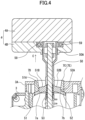
- the operation restriction release button 54 Upon the operation restriction release button 54 being pushed in the direction of the arrow D in FIG. 5 , the contact 57 is pushed along the cam surface 56B, and the slide member 50 is pushed down in the direction of the arrow E in FIG. 5 . Due to the action of the cam mechanism 55, the pushing driving force of the operation restriction release button 54 is transferred to a push-down for the operation lever 2 (the direction of the arrow E in FIG. 5 ).
- the slide member 50 pushed down, the first locking portion 51A and the second locking portion 52A of the slide member 50 separate from the lower end edges 7a and 7b of the shift gate portion 7 and the operation restriction state with respect to the operation lever 2 of the lock mechanism 5 is released. Thereby, the operation lever 2 becomes able to be operated and moved. After the operation lever 2 is operated and moved, the operation lever 2 is configured to automatically return to the home position 7A by the return mechanism.
- the operation restriction release button 54 is operated to be pushed in the direction of the arrow D in FIG. 5 .
- the action of the lock mechanism 5 is released.
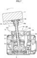
- the operation lever can be swung in the direction of the arrow A in FIG. 7 (the direction of the arrow A in FIG. 3 ), and the operation lever 2 can be operated to be moved in the direction towards the rear position 7D.
- a non-illustrated position detection unit incorporated in the housing 3 such as a magnetic sensor, detects that the operation lever 2 is operated to the rear position 7D.
- the detection signal detected by the magnetic sensor is transmitted to a gear driving unit, and the vehicle can select a state of reverse driving corresponding to the R position.
- the lock mechanism 5 is released in a manner similar to that of the movement operation of the rear position 7D, and the operation lever 2 is operated to be moved in the direction of the arrow B in FIG. 3 .
- the magnetic sensor it is detected by the magnetic sensor that the operation lever 2 is located at the front position 7C, and the vehicle can select a state of forward driving corresponding to the D position.
- a movement operation of the operation lever 2 from the home position 7A to the front position 7C is repeatedly performed twice.
- the state of the vehicle changes from the N position to the D position, and subsequently, changes from the D position to the S position to enable deceleration driving corresponding to the S position.
- the lighting display of the position display plate sequentially moves from the N position to the D position, and from the D position to the S position. Note that also when the operation lever 2 is returned to the home position 7A, because a detection signal corresponding to the position is transmitted to the gear driving unit, it is detected whether the operation lever 2 is reliably returned at the time of repeated operations.
- the solid operation lever 2 can be used as the operation lever 2, the strength of the operation lever 2 can be secured. Also, the components of the lock mechanism 5, such as the slide member 50, that restricts the movement operation of the operation lever 2 are attached to the outside of the operation lever 2, and the assembly property of the components of the lock mechanism 5 is favorable.
- the locking portions 51A and 52A and the guide portions 51B and 52B constituting the lock mechanism 5 are formed together with the slide member 50, the number of components is few, the component cost can be reduced, and the assembling property is preferable.
- the restriction of the operation lever 2 can be released at the home position 7A, and the operation lever 2 can be operated to be moved in a desired direction reliably.
- the operation knob 4 and the operation lever 2 can be mounted to be together inside the cylindrical slide member 50, the mounting space of the components is efficient and the movement amount of the slide member 50 can also be secured.
- the operation lever 2 is necessarily returned to the home position 7A after a movement operation, a next movement operation can be easily and reliably performed.
- FIG. 8 is a cross-sectional view of a shift device according to a second embodiment of the present invention.
- FIG. 9 is a cross-sectional view illustrating a state in which the lock mechanism of the shift device, which is illustrated in FIG. 8 , is released and operated to be at the D position. Because the shift device 60 of the second embodiment basically has the same configuration as that of the shift device 1 of the first embodiment except for the configuration for releasing the operation restriction of the lock mechanism 5, the same reference numerals are attached to the same elements such that their descriptions are omitted.
- the cylindrical slide member 50 constituting the lock mechanism 5 of the shift device 60 is assembled to be able to be reciprocated along the outer periphery of the operation lever 2, its front end side is formed to have a larger diameter than that of the main body side, and a locking portion 61 is formed on the front end side.
- the locking portion 61 is fitted in a cylindrical portion 63 hanging down at the center portion of the rear surface of a cylindrical operation knob 62, and the slide member 50 is mounted together with the operation knob 62.
- a gap 64 for allowing a movement of the slide member 50 is formed between the tip 2a of the operation lever 2 and the upper surface 63A inside the cylindrical portion 63.
- protrusion portions 51 and 52 which constitute the lock mechanism 5, are formed, and locking portions 51A and 52 and guide portions 51B and 52B are formed on the protrusion portions 51 and 52.
- the movement operation can be performed by releasing the operation restriction of the operation lever 2 by a pushing operation of the operation knob 62.
- the shift device 60 when the operation lever 2 is operated to be at a respective position, the position is detected by a shift position detection unit, such as a magnetic sensor, in a manner similar to that in the shift device 1 according to the first embodiment.
- a shift position detection unit such as a magnetic sensor
- the shift device 60 according to the second embodiment as with the shift device 1 according to the first embodiment, it is possible to release the restriction of the operation lever 2 at the home position 7A and to operate the operation lever 2 to move in a desired direction reliably.
- FIG. 10 is a plan view of a shift device according to a third embodiment of the present invention.
- FIG. 11 is a diagram that describes shift positions in which (a) is a plan view illustrating a gate portion of the shift device, and (b) is a schematic view illustrating an arrangement of the positions of the operation lever. Because a shift device 70 of the third embodiment basically has the same configuration as that of the shift device 1 of the first embodiment except for the configuration of an arrangement of positions, the same reference numerals are attached to the same elements such that their descriptions are omitted.
- the operation restriction release button 54 is incorporated as in the shift device 1 of the first embodiment.
- An upper cover 72A is attached to an upper portion of a housing 72.
- a vertically long gate portion 73 for guiding and defining a movement operation direction of the operation lever 2 is opened and formed on the substantially central portion of the upper cover 72A.
- a home position 73A is provided at the central position of the gate portion 73.
- a front position 73C that is a first position and a rear position 73D that is a second position are provided at positions between which the home position 73A is interposed in the front-rear direction (vertical direction in FIG. 11 (a) ).
- the N position 73B that is a neutral position of the operation lever 2 is provided at a position in a direction orthogonal to the operation direction of the front position 73C and the rear position 73D.
- a position display plate (which is not illustrated) is attached near the upper cover 72A of the housing 72. As illustrated in FIG. 11 (b) , on the position display plate, characters 200 that indicate the respective positions of the operation lever 2 are formed.
- the driver When a driver operates the operation lever 2 to move to a respective position 73A, 73C, or 73D, the driver can operate the operation lever 2 to move to a desired position while confirming the characters 200 indicating the position state of the vehicle as in the shift device 1 of the first embodiment.
- the operation restriction release button 54 is operated to be pushed at the home position 73A.
- the restriction of the movement operation of the operation lever 2 is released.
- the operation lever 2 is operated to be moved from the home position 73A towards the N position 73B.
- shift device 70 when the operation lever 2 is operated to be moved to a respective position, the position is detected by a shift position detection unit, such as a magnetic sensor, in a manner similar to that in the shift device 1 according to the first embodiment.
- a shift position detection unit such as a magnetic sensor
- the operation lever 2 does not switch to the N position 73B not intended by the driver. Therefore, the operation lever 2 can be reliably operated to be moved to the N position 73B as intended.
- shift devices of the above described embodiments are a type of a shift device in which an operation lever automatically returns to the home position upon a movement operation being released
- shift devices are not limited to this and may be a type of a shift device in which, even when the operation after a movement operation is released, an operation lever is retained at a shift position after the movement.
- each shift position of the position display plate is not limited to the above described embodiments, and can be changed as appropriate.
- the operation restriction release button 54 is protruded in a direction perpendicular to the movement direction of the operation lever 2 in embodiments described above, the operation restriction release button 54 is not limited to this and may be changed to protrude frontward or backward in the same direction as the movement direction of the operation lever 2, for example.
- the present invention can be applied to various shift devices in which an operation lever is operated to be moved to a plurality of positions, and is also applicable to a multi-directional input device that inputs, according to operations of an operation lever in multiple directions, various signals.
Landscapes
- Engineering & Computer Science (AREA)
- Physics & Mathematics (AREA)
- General Physics & Mathematics (AREA)
- Automation & Control Theory (AREA)
- Chemical & Material Sciences (AREA)
- Combustion & Propulsion (AREA)
- Transportation (AREA)
- Mechanical Engineering (AREA)
- Arrangement Or Mounting Of Control Devices For Change-Speed Gearing (AREA)
Claims (6)
- Dispositif de changement de vitesse (1) comprenant :un bouton de commande (4) ;un levier de commande (2) ; etun mécanisme de verrouillage (5) configuré de manière à restreindre un mouvement du levier de commande (2) dans une position de repos (7A),dans lequel le mécanisme de verrouillage (5) inclut un élément coulissant cylindrique (50) conçu pour être mobile dans une direction axiale le long d'une périphérie extérieure du levier de commande (2), etdans lequel le mouvement du levier de commande (2) est restreint, ou bien sa restriction est levée, par un mouvement de l'élément coulissant (50) ;dans lequel une partie de verrouillage (51A, 52A), configurée pour restreindre le mouvement du levier de commande (2) en position de repos (7A), et une partie de guidage (51B, 52B), configurée pour guider un mouvement du levier de commande (2) une fois que la restriction du mouvement du levier de commande (2) est levée, sont intégralement formées sur l'élément coulissant (50) ;caractérisé en ce quele levier de commande (2) est configuré pour être actionné afin d'être déplacé dans une pluralité de positions par le bouton de commande (4) en vue de sélectionner un état de conduite.
- Le dispositif de changement de vitesse (1) selon la revendication 1, dans lequel un bouton de levée de la restriction de commande (54) pouvant être poussé dans une direction orthogonale à une direction de mouvement de l'élément coulissant (50) est incorporé au bouton de commande (4), un mécanisme de came (55) qui transfère une force d'entraînement du bouton de levée de la restriction de commande (54) à la direction de mouvement de l'élément coulissant (50) est prévu entre le bouton de levée de la restriction de commande (54) et l'élément coulissant (50), et la restriction du mouvement du levier de commande (2) est levée par une opération de poussée du bouton de levée de la restriction de commande (54).
- Le dispositif de changement de vitesse (1) selon la revendication 1 ou 2, dans lequel le bouton de commande (4) et le levier de commande (2) ont intégralement montés par une partie de connexion (9) prévue dans l'élément coulissant (50).
- Le dispositif de changement de vitesse (1) selon la revendication 1, dans lequel l'élément coulissant (50) est intégralement fixé au bouton de commande (4), et la restriction du mouvement du levier de commande (2) est levée en poussant le bouton de commande (4) dans la direction axiale du levier de commande (2).
- Le dispositif de changement de vitesse (1) selon l'une quelconque des revendications 1 à 4, comprenant en outre : un mécanisme de retour configuré pour ramener automatiquement le levier de commande (2) à la position de repos (7A) après le mouvement du levier de commande (2).
- Le dispositif de changement de vitesse (1) selon l'une quelconque des revendications 1 à 5, dans lequel une première position et une deuxième position sont prévues à des positions situées de part et d'autre de la position de repos (7A) dans une direction linéaire, et une position neutre du levier de commande (2) est prévue à une position qui se situe dans une direction différente de la direction de mouvement de la première position et de la deuxième position.
Applications Claiming Priority (2)
| Application Number | Priority Date | Filing Date | Title |
|---|---|---|---|
| JP2016052755 | 2016-03-16 | ||
| PCT/JP2017/005317 WO2017159179A1 (fr) | 2016-03-16 | 2017-02-14 | Dispositif de changement de vitesse |
Publications (3)
| Publication Number | Publication Date |
|---|---|
| EP3431317A1 EP3431317A1 (fr) | 2019-01-23 |
| EP3431317A4 EP3431317A4 (fr) | 2019-04-24 |
| EP3431317B1 true EP3431317B1 (fr) | 2024-12-04 |
Family
ID=59850664
Family Applications (1)
| Application Number | Title | Priority Date | Filing Date |
|---|---|---|---|
| EP17766186.5A Active EP3431317B1 (fr) | 2016-03-16 | 2017-02-14 | Dispositif de changement de vitesse |
Country Status (3)
| Country | Link |
|---|---|
| EP (1) | EP3431317B1 (fr) |
| JP (1) | JP6589049B2 (fr) |
| WO (1) | WO2017159179A1 (fr) |
Families Citing this family (1)
| Publication number | Priority date | Publication date | Assignee | Title |
|---|---|---|---|---|
| JP2023152543A (ja) * | 2022-04-04 | 2023-10-17 | 株式会社東海理化電機製作所 | シフト装置 |
Family Cites Families (9)
| Publication number | Priority date | Publication date | Assignee | Title |
|---|---|---|---|---|
| JPS58105316A (ja) * | 1981-12-17 | 1983-06-23 | Kojima Press Co Ltd | 車両用自動変速機のシフトレバ−装置 |
| JP2771034B2 (ja) * | 1990-11-30 | 1998-07-02 | 日産車体株式会社 | 自動変速機の操作装置 |
| JPH11245680A (ja) * | 1998-02-27 | 1999-09-14 | Fuji Kiko Co Ltd | シフトレバー装置 |
| JP2000038045A (ja) * | 1998-07-24 | 2000-02-08 | Tokai Rika Co Ltd | シフトレバー装置 |
| JP5624561B2 (ja) * | 2010-01-19 | 2014-11-12 | 本田技研工業株式会社 | シフト装置 |
| JP2012046096A (ja) * | 2010-08-27 | 2012-03-08 | Fuji Kiko Co Ltd | シフトレバー装置 |
| JP2013039869A (ja) * | 2011-08-15 | 2013-02-28 | Suzuki Motor Corp | 手動変速機の誤操作防止装置 |
| JP5880397B2 (ja) * | 2012-11-12 | 2016-03-09 | マツダ株式会社 | 車両のシフト装置 |
| JP2014201185A (ja) * | 2013-04-04 | 2014-10-27 | スズキ株式会社 | 変速機のレバー装置 |
-
2017
- 2017-02-14 EP EP17766186.5A patent/EP3431317B1/fr active Active
- 2017-02-14 JP JP2018505356A patent/JP6589049B2/ja active Active
- 2017-02-14 WO PCT/JP2017/005317 patent/WO2017159179A1/fr not_active Ceased
Also Published As
| Publication number | Publication date |
|---|---|
| JP6589049B2 (ja) | 2019-10-09 |
| JPWO2017159179A1 (ja) | 2018-11-29 |
| WO2017159179A1 (fr) | 2017-09-21 |
| EP3431317A4 (fr) | 2019-04-24 |
| EP3431317A1 (fr) | 2019-01-23 |
Similar Documents
| Publication | Publication Date | Title |
|---|---|---|
| KR101394773B1 (ko) | 시프트 캐리지 록을 구비한 작동 장치 | |
| EP2813652A1 (fr) | Dispositif de déclenchement de verrou de portière de véhicule | |
| US20090223798A1 (en) | Slide operation type electrical component | |
| US8904898B2 (en) | Electronic shift lever for improving operability in automatic transmission | |
| EP3054196B1 (fr) | Dispositif de changement de vitesses | |
| JP4564893B2 (ja) | シフト装置 | |
| CN105705364B (zh) | 变速杆装置 | |
| JP2007062664A (ja) | シフト装置 | |
| JP6610633B2 (ja) | 車両用シフタ装置 | |
| EP3431317B1 (fr) | Dispositif de changement de vitesse | |
| JP5357095B2 (ja) | シフトレバー装置 | |
| JP2019217911A (ja) | 車両用シフタ装置 | |
| EP3680747B1 (fr) | Dispositif d'actionnement | |
| EP3680746B1 (fr) | Dispositif d'actionnement | |
| EP1909158B1 (fr) | Elément d'actionnement | |
| JP4575849B2 (ja) | シフトスイッチ | |
| CN101603591A (zh) | 用于避免误换档的装置 | |
| JP5137197B2 (ja) | ポジションスイッチ装置 | |
| JP6653975B2 (ja) | Atシフトレバー装置 | |
| JP2006347305A (ja) | シフト装置 | |
| JP5050072B2 (ja) | シフトレバー装置 | |
| CN210423677U (zh) | 操纵机构、变速箱和车辆 | |
| JP2017190050A (ja) | シフト装置 | |
| JP2017119445A (ja) | シフト装置 | |
| JPH0741926U (ja) | スイッチ装置 |
Legal Events
| Date | Code | Title | Description |
|---|---|---|---|
| STAA | Information on the status of an ep patent application or granted ep patent |
Free format text: STATUS: THE INTERNATIONAL PUBLICATION HAS BEEN MADE |
|
| PUAI | Public reference made under article 153(3) epc to a published international application that has entered the european phase |
Free format text: ORIGINAL CODE: 0009012 |
|
| STAA | Information on the status of an ep patent application or granted ep patent |
Free format text: STATUS: REQUEST FOR EXAMINATION WAS MADE |
|
| 17P | Request for examination filed |
Effective date: 20180817 |
|
| AK | Designated contracting states |
Kind code of ref document: A1 Designated state(s): AL AT BE BG CH CY CZ DE DK EE ES FI FR GB GR HR HU IE IS IT LI LT LU LV MC MK MT NL NO PL PT RO RS SE SI SK SM TR |
|
| AX | Request for extension of the european patent |
Extension state: BA ME |
|
| RAP1 | Party data changed (applicant data changed or rights of an application transferred) |
Owner name: ALPS ALPINE CO., LTD. |
|
| A4 | Supplementary search report drawn up and despatched |
Effective date: 20190325 |
|
| RIC1 | Information provided on ipc code assigned before grant |
Ipc: G05G 1/08 20060101ALI20190319BHEP Ipc: G05G 1/04 20060101ALI20190319BHEP Ipc: G05G 1/02 20060101ALI20190319BHEP Ipc: B60K 20/02 20060101AFI20190319BHEP |
|
| DAV | Request for validation of the european patent (deleted) | ||
| DAX | Request for extension of the european patent (deleted) | ||
| STAA | Information on the status of an ep patent application or granted ep patent |
Free format text: STATUS: EXAMINATION IS IN PROGRESS |
|
| 17Q | First examination report despatched |
Effective date: 20190905 |
|
| GRAP | Despatch of communication of intention to grant a patent |
Free format text: ORIGINAL CODE: EPIDOSNIGR1 |
|
| STAA | Information on the status of an ep patent application or granted ep patent |
Free format text: STATUS: GRANT OF PATENT IS INTENDED |
|
| INTG | Intention to grant announced |
Effective date: 20240718 |
|
| GRAS | Grant fee paid |
Free format text: ORIGINAL CODE: EPIDOSNIGR3 |
|
| GRAA | (expected) grant |
Free format text: ORIGINAL CODE: 0009210 |
|
| STAA | Information on the status of an ep patent application or granted ep patent |
Free format text: STATUS: THE PATENT HAS BEEN GRANTED |
|
| AK | Designated contracting states |
Kind code of ref document: B1 Designated state(s): AL AT BE BG CH CY CZ DE DK EE ES FI FR GB GR HR HU IE IS IT LI LT LU LV MC MK MT NL NO PL PT RO RS SE SI SK SM TR |
|
| REG | Reference to a national code |
Ref country code: GB Ref legal event code: FG4D |
|
| REG | Reference to a national code |
Ref country code: CH Ref legal event code: EP |
|
| REG | Reference to a national code |
Ref country code: DE Ref legal event code: R096 Ref document number: 602017086549 Country of ref document: DE |
|
| REG | Reference to a national code |
Ref country code: IE Ref legal event code: FG4D |
|
| REG | Reference to a national code |
Ref country code: LT Ref legal event code: MG9D |
|
| REG | Reference to a national code |
Ref country code: NL Ref legal event code: MP Effective date: 20241204 |
|
| PG25 | Lapsed in a contracting state [announced via postgrant information from national office to epo] |
Ref country code: HR Free format text: LAPSE BECAUSE OF FAILURE TO SUBMIT A TRANSLATION OF THE DESCRIPTION OR TO PAY THE FEE WITHIN THE PRESCRIBED TIME-LIMIT Effective date: 20241204 |
|
| PG25 | Lapsed in a contracting state [announced via postgrant information from national office to epo] |
Ref country code: FI Free format text: LAPSE BECAUSE OF FAILURE TO SUBMIT A TRANSLATION OF THE DESCRIPTION OR TO PAY THE FEE WITHIN THE PRESCRIBED TIME-LIMIT Effective date: 20241204 |
|
| PG25 | Lapsed in a contracting state [announced via postgrant information from national office to epo] |
Ref country code: BG Free format text: LAPSE BECAUSE OF FAILURE TO SUBMIT A TRANSLATION OF THE DESCRIPTION OR TO PAY THE FEE WITHIN THE PRESCRIBED TIME-LIMIT Effective date: 20241204 |
|
| PG25 | Lapsed in a contracting state [announced via postgrant information from national office to epo] |
Ref country code: ES Free format text: LAPSE BECAUSE OF FAILURE TO SUBMIT A TRANSLATION OF THE DESCRIPTION OR TO PAY THE FEE WITHIN THE PRESCRIBED TIME-LIMIT Effective date: 20241204 |
|
| PG25 | Lapsed in a contracting state [announced via postgrant information from national office to epo] |
Ref country code: NO Free format text: LAPSE BECAUSE OF FAILURE TO SUBMIT A TRANSLATION OF THE DESCRIPTION OR TO PAY THE FEE WITHIN THE PRESCRIBED TIME-LIMIT Effective date: 20250304 |
|
| PG25 | Lapsed in a contracting state [announced via postgrant information from national office to epo] |
Ref country code: LV Free format text: LAPSE BECAUSE OF FAILURE TO SUBMIT A TRANSLATION OF THE DESCRIPTION OR TO PAY THE FEE WITHIN THE PRESCRIBED TIME-LIMIT Effective date: 20241204 Ref country code: GR Free format text: LAPSE BECAUSE OF FAILURE TO SUBMIT A TRANSLATION OF THE DESCRIPTION OR TO PAY THE FEE WITHIN THE PRESCRIBED TIME-LIMIT Effective date: 20250305 |
|
| PG25 | Lapsed in a contracting state [announced via postgrant information from national office to epo] |
Ref country code: RS Free format text: LAPSE BECAUSE OF FAILURE TO SUBMIT A TRANSLATION OF THE DESCRIPTION OR TO PAY THE FEE WITHIN THE PRESCRIBED TIME-LIMIT Effective date: 20250304 |
|
| PG25 | Lapsed in a contracting state [announced via postgrant information from national office to epo] |
Ref country code: NL Free format text: LAPSE BECAUSE OF FAILURE TO SUBMIT A TRANSLATION OF THE DESCRIPTION OR TO PAY THE FEE WITHIN THE PRESCRIBED TIME-LIMIT Effective date: 20241204 |
|
| REG | Reference to a national code |
Ref country code: AT Ref legal event code: MK05 Ref document number: 1747830 Country of ref document: AT Kind code of ref document: T Effective date: 20241204 |
|
| PG25 | Lapsed in a contracting state [announced via postgrant information from national office to epo] |
Ref country code: SM Free format text: LAPSE BECAUSE OF FAILURE TO SUBMIT A TRANSLATION OF THE DESCRIPTION OR TO PAY THE FEE WITHIN THE PRESCRIBED TIME-LIMIT Effective date: 20241204 |
|
| PG25 | Lapsed in a contracting state [announced via postgrant information from national office to epo] |
Ref country code: PL Free format text: LAPSE BECAUSE OF FAILURE TO SUBMIT A TRANSLATION OF THE DESCRIPTION OR TO PAY THE FEE WITHIN THE PRESCRIBED TIME-LIMIT Effective date: 20241204 |
|
| PG25 | Lapsed in a contracting state [announced via postgrant information from national office to epo] |
Ref country code: IS Free format text: LAPSE BECAUSE OF FAILURE TO SUBMIT A TRANSLATION OF THE DESCRIPTION OR TO PAY THE FEE WITHIN THE PRESCRIBED TIME-LIMIT Effective date: 20250404 |
|
| PG25 | Lapsed in a contracting state [announced via postgrant information from national office to epo] |
Ref country code: PT Free format text: LAPSE BECAUSE OF FAILURE TO SUBMIT A TRANSLATION OF THE DESCRIPTION OR TO PAY THE FEE WITHIN THE PRESCRIBED TIME-LIMIT Effective date: 20250404 |
|
| PG25 | Lapsed in a contracting state [announced via postgrant information from national office to epo] |
Ref country code: EE Free format text: LAPSE BECAUSE OF FAILURE TO SUBMIT A TRANSLATION OF THE DESCRIPTION OR TO PAY THE FEE WITHIN THE PRESCRIBED TIME-LIMIT Effective date: 20241204 |
|
| PG25 | Lapsed in a contracting state [announced via postgrant information from national office to epo] |
Ref country code: AT Free format text: LAPSE BECAUSE OF FAILURE TO SUBMIT A TRANSLATION OF THE DESCRIPTION OR TO PAY THE FEE WITHIN THE PRESCRIBED TIME-LIMIT Effective date: 20241204 Ref country code: RO Free format text: LAPSE BECAUSE OF FAILURE TO SUBMIT A TRANSLATION OF THE DESCRIPTION OR TO PAY THE FEE WITHIN THE PRESCRIBED TIME-LIMIT Effective date: 20241204 |
|
| PG25 | Lapsed in a contracting state [announced via postgrant information from national office to epo] |
Ref country code: SK Free format text: LAPSE BECAUSE OF FAILURE TO SUBMIT A TRANSLATION OF THE DESCRIPTION OR TO PAY THE FEE WITHIN THE PRESCRIBED TIME-LIMIT Effective date: 20241204 |
|
| PG25 | Lapsed in a contracting state [announced via postgrant information from national office to epo] |
Ref country code: CZ Free format text: LAPSE BECAUSE OF FAILURE TO SUBMIT A TRANSLATION OF THE DESCRIPTION OR TO PAY THE FEE WITHIN THE PRESCRIBED TIME-LIMIT Effective date: 20241204 |
|
| PG25 | Lapsed in a contracting state [announced via postgrant information from national office to epo] |
Ref country code: IT Free format text: LAPSE BECAUSE OF FAILURE TO SUBMIT A TRANSLATION OF THE DESCRIPTION OR TO PAY THE FEE WITHIN THE PRESCRIBED TIME-LIMIT Effective date: 20241204 |
|
| REG | Reference to a national code |
Ref country code: DE Ref legal event code: R097 Ref document number: 602017086549 Country of ref document: DE |
|
| PG25 | Lapsed in a contracting state [announced via postgrant information from national office to epo] |
Ref country code: SE Free format text: LAPSE BECAUSE OF FAILURE TO SUBMIT A TRANSLATION OF THE DESCRIPTION OR TO PAY THE FEE WITHIN THE PRESCRIBED TIME-LIMIT Effective date: 20241204 |
|
| PG25 | Lapsed in a contracting state [announced via postgrant information from national office to epo] |
Ref country code: MC Free format text: LAPSE BECAUSE OF FAILURE TO SUBMIT A TRANSLATION OF THE DESCRIPTION OR TO PAY THE FEE WITHIN THE PRESCRIBED TIME-LIMIT Effective date: 20241204 |
|
| REG | Reference to a national code |
Ref country code: CH Ref legal event code: PL |
|
| PG25 | Lapsed in a contracting state [announced via postgrant information from national office to epo] |
Ref country code: DK Free format text: LAPSE BECAUSE OF FAILURE TO SUBMIT A TRANSLATION OF THE DESCRIPTION OR TO PAY THE FEE WITHIN THE PRESCRIBED TIME-LIMIT Effective date: 20241204 |
|
| PLBE | No opposition filed within time limit |
Free format text: ORIGINAL CODE: 0009261 |
|
| STAA | Information on the status of an ep patent application or granted ep patent |
Free format text: STATUS: NO OPPOSITION FILED WITHIN TIME LIMIT |
|
| PG25 | Lapsed in a contracting state [announced via postgrant information from national office to epo] |
Ref country code: LU Free format text: LAPSE BECAUSE OF NON-PAYMENT OF DUE FEES Effective date: 20250214 |
|
| PG25 | Lapsed in a contracting state [announced via postgrant information from national office to epo] |
Ref country code: CH Free format text: LAPSE BECAUSE OF NON-PAYMENT OF DUE FEES Effective date: 20250228 |
|
| 26N | No opposition filed |
Effective date: 20250905 |
|
| GBPC | Gb: european patent ceased through non-payment of renewal fee |
Effective date: 20250304 |
|
| REG | Reference to a national code |
Ref country code: BE Ref legal event code: MM Effective date: 20250228 |
|
| PG25 | Lapsed in a contracting state [announced via postgrant information from national office to epo] |
Ref country code: GB Free format text: LAPSE BECAUSE OF NON-PAYMENT OF DUE FEES Effective date: 20250304 |
|
| PG25 | Lapsed in a contracting state [announced via postgrant information from national office to epo] |
Ref country code: FR Free format text: LAPSE BECAUSE OF NON-PAYMENT OF DUE FEES Effective date: 20250228 |
|
| PG25 | Lapsed in a contracting state [announced via postgrant information from national office to epo] |
Ref country code: BE Free format text: LAPSE BECAUSE OF NON-PAYMENT OF DUE FEES Effective date: 20250228 |
|
| PG25 | Lapsed in a contracting state [announced via postgrant information from national office to epo] |
Ref country code: IE Free format text: LAPSE BECAUSE OF NON-PAYMENT OF DUE FEES Effective date: 20250214 |
|
| PGFP | Annual fee paid to national office [announced via postgrant information from national office to epo] |
Ref country code: DE Payment date: 20260218 Year of fee payment: 10 |