EP2013652B1 - Roue de couleurs - Google Patents
Roue de couleurs Download PDFInfo
- Publication number
- EP2013652B1 EP2013652B1 EP07723836A EP07723836A EP2013652B1 EP 2013652 B1 EP2013652 B1 EP 2013652B1 EP 07723836 A EP07723836 A EP 07723836A EP 07723836 A EP07723836 A EP 07723836A EP 2013652 B1 EP2013652 B1 EP 2013652B1
- Authority
- EP
- European Patent Office
- Prior art keywords
- ring
- segments
- filter segments
- shaft
- color
- Prior art date
- Legal status (The legal status is an assumption and is not a legal conclusion. Google has not performed a legal analysis and makes no representation as to the accuracy of the status listed.)
- Active
Links
Images
Classifications
-
- G—PHYSICS
- G02—OPTICS
- G02B—OPTICAL ELEMENTS, SYSTEMS OR APPARATUS
- G02B5/00—Optical elements other than lenses
-
- G—PHYSICS
- G02—OPTICS
- G02B—OPTICAL ELEMENTS, SYSTEMS OR APPARATUS
- G02B26/00—Optical devices or arrangements for the control of light using movable or deformable optical elements
- G02B26/007—Optical devices or arrangements for the control of light using movable or deformable optical elements the movable or deformable optical element controlling the colour, i.e. a spectral characteristic, of the light
- G02B26/008—Optical devices or arrangements for the control of light using movable or deformable optical elements the movable or deformable optical element controlling the colour, i.e. a spectral characteristic, of the light in the form of devices for effecting sequential colour changes, e.g. colour wheels
-
- G—PHYSICS
- G02—OPTICS
- G02B—OPTICAL ELEMENTS, SYSTEMS OR APPARATUS
- G02B5/00—Optical elements other than lenses
- G02B5/20—Filters
-
- G—PHYSICS
- G03—PHOTOGRAPHY; CINEMATOGRAPHY; ANALOGOUS TECHNIQUES USING WAVES OTHER THAN OPTICAL WAVES; ELECTROGRAPHY; HOLOGRAPHY
- G03B—APPARATUS OR ARRANGEMENTS FOR TAKING PHOTOGRAPHS OR FOR PROJECTING OR VIEWING THEM; APPARATUS OR ARRANGEMENTS EMPLOYING ANALOGOUS TECHNIQUES USING WAVES OTHER THAN OPTICAL WAVES; ACCESSORIES THEREFOR
- G03B33/00—Colour photography, other than mere exposure or projection of a colour film
- G03B33/08—Sequential recording or projection
-
- H—ELECTRICITY
- H04—ELECTRIC COMMUNICATION TECHNIQUE
- H04N—PICTORIAL COMMUNICATION, e.g. TELEVISION
- H04N9/00—Details of colour television systems
- H04N9/12—Picture reproducers
- H04N9/31—Projection devices for colour picture display, e.g. using electronic spatial light modulators [ESLM]
- H04N9/3102—Projection devices for colour picture display, e.g. using electronic spatial light modulators [ESLM] using two-dimensional electronic spatial light modulators
- H04N9/3111—Projection devices for colour picture display, e.g. using electronic spatial light modulators [ESLM] using two-dimensional electronic spatial light modulators for displaying the colours sequentially, e.g. by using sequentially activated light sources
- H04N9/3114—Projection devices for colour picture display, e.g. using electronic spatial light modulators [ESLM] using two-dimensional electronic spatial light modulators for displaying the colours sequentially, e.g. by using sequentially activated light sources by using a sequential colour filter producing one colour at a time
-
- G—PHYSICS
- G02—OPTICS
- G02B—OPTICAL ELEMENTS, SYSTEMS OR APPARATUS
- G02B7/00—Mountings, adjusting means, or light-tight connections, for optical elements
- G02B7/006—Filter holders
Definitions
- the present invention relates to color wheels and projectors in which color wheels are used to generate a color sequential lighting.
- the present invention also relates to the production of such color wheels.
- Color wheels of the aforementioned type are generally used in applications where color changes are needed in rapid succession. Examples of applications that use such components include image generators or display assemblies. Rear or front projection systems for televisions are typical applications.
- a disk-shaped element is typically used which is provided at its periphery with circularly arranged filter segments, thereby forming a ring.
- a circle segment can be described as an area cut off from the rest of a circle by a secant.
- the circle segment is the area that does not encompass the center of the circle and that lies between the secant and one of the circular arcs defined by the secant.
- the word segment is used in the context of the present description for a geometric shape, which in the mathematical sense rather than sector a ring, which is equipped with an outer circular arc and an inner circular arc and two radial edges.
- the inner arc of the segment according to the present invention may be modified and therefore deviate considerably from the inner arc of the original ring. It even happens that the inner arc does not even have the shape of a circular arc.
- the color ring is rotated about the central axis. By rapid rotation of the color ring, the filter segments are periodically moved in and out of the optical path, producing a fast color change. To accomplish this rotation, the color ring is attached to a motor. Color ring and motor then form the color wheel.
- the color change must proceed in a very rapid sequence.
- the filter segments have to be moved very fast through the optical path, ie the fast rotation of the ring is mandatory.
- large forces are applied to the color ring, and in particular to the sensitive filters, due to accelerations exceeding the gravitational acceleration g several hundred times. For especially good quality in image projection, these accelerations can even exceed 1000g.
- the radial balancing of the component must be very good in order to achieve a long service life.
- the image projectors are also subject to very high requirements with regard to image brightness, which can only be met with powerful light sources. Due to these strong light sources, the color ring is exposed to high temperatures of up to 100 ° C.
- these products often have to withstand temperatures down to -20 ° C and below. This is often the case when the products are stored before sale. In addition, for example, during transportation to the countries where the projectors, and with them the color wheels, are sold, these low temperatures must be endured. This often leads to temperatures of -40 ° C or below.
- FIG EP 0 615 146 A2 A color wheel for use in an image projector with circular filter segments is shown in FIG EP 0 615 146 A2 described.
- the filter segments are mounted on a glass ring.
- a disadvantage of this optical element is due to the fact that when used in the optical path, high intensity light has to transmit through an area comprising adhesive. Most adhesives do not hold such intensity. It is a further disadvantage of this arrangement that the glass ring is expensive. In addition, precise radial balancing is difficult to achieve. The glass ring leads to additional light losses, which makes the entire component inefficient.
- the planar filter segments are adhered to the periphery of a disc-shaped carrier such that the annular transparent surface between the filter segments in the direction of rotation is not interrupted by materials that are not optically transparent.
- the color filter segments are bonded across the surface to the support in strip-like zones pointing in the direction of the axis of rotation. The bonding of the surface extends only over a narrow annular zone area in the direction of the center of rotation, so that a large part of the surface of the filter segments, seen radially, remains free from the axis of rotation into the outer space, as a transparent annular usable zone. Additional fasteners for the openings, such as holes in the filters, can be completely avoided.
- Low operating speeds range from 4000 rpm to ⁇ 10000 rpm and are typically around 7200 rpm.
- High operating speeds range from 10,000 rpm to 25,000 rpm and are typically 14400 rpm.
- the choice of adhesive used to adhere the color filter segments to the carrier is of particular interest.
- US 2004/0066495 suggests an arrangement with an outer ring.
- the filters are attached to each other in a manner that surrounds a circular disk.
- a circular color wheel is first created by fixing the filters to the circular disk.
- the color wheel is placed in the receiving groove of the outer ring. Therefore, the outer ring must be produced with some tolerance, resulting in gaps between the ring and the outer edge of the filter segments.
- the outer ring is formed of material having a higher CTE than the material of the filter segments. Filter segments are typically glass segments and ring materials of equal or lower CTE are difficult to find.
- a color wheel with motor and color ring arranged thereon wherein the color ring comprises a shaft, a carrier and a number of filter segments.
- the carrier has the shape of an outer ring in which the filter segments are firmly mounted.
- the object can be achieved according to the invention by the previously known solution is modified with an outer ring.
- the prior art color wheels should be modified such that the strain exerted on the color wheels during rotation undergoes compression.
- the color ring comprises a shaft for rotating the ring, the shaft having a central axis about which it can be rotated.
- the shaft should be arranged on the color ring so that the filter segments during rotation experience of the color ring radial compressive forces.
- the first possibility is to provide a contact between the outer ring and filter segments, which is significantly harder than the hardness of the contact between the filter segments and the shaft.
- the carrier is an outer ring and not the shaft.
- the filter segments are merely fixed to the outer ring and the edges of the segments are in close contact with this ring while merely being loosely packed between features on the shaft.
- the color ring is made by fixing the filter segments to the outer ring before placing the shaft on the ring.
- the second way to reduce, eliminate or convert the strain forces within the filter segments is to mount the color wheel in such a way that when the ring is not rotating, compression is already applied to the filter segments.
- This can be achieved, for example, in that the inner diameter of the outer ring is a little smaller at room temperature than the outer diameter of already attached to a shaft segments. Then, the outer ring, and only this, is heated to a temperature above the operating temperature of the color wheel. Because of the thermal expansion of the outer ring this can now be arranged on the segments. Upon cooling, the outer ring will tend to shrink in size and will therefore exert compression pressure on the segments.
- the outer ring usually decreases faster with decreasing temperature than the size of the filter segments, it may be advantageous, especially when temperatures below 0 ° C to -20 ° C, -40 ° C or below may occur, distances between the segments or to assemble them at low temperatures.
- the third option is to use different materials for the outer ring and the stem, the difference being manifested particularly in the CTEs.
- stainless steel for the outer ring and aluminum for the shaft could be used. Everything is assembled at room temperature to a color ring, for example with a UV curing adhesive curing at room temperature, heating the component to operating temperature has the effect that the steel ring expands far less than the aluminum sheath so that the filter segments are compressed.
- the invention is characterized in that elastic means are provided for fastening the shaft to the filter segments on the shaft, which press the segments radially outward.
- the process of manufacturing color wheels begins with providing the different parts. Filter segments, a motor, a shaft and a ring-shaped carrier are required.
- Substrates for filter segments can be, for example, colored and / or coated glass plates.
- the required geometry of the filter segments can be achieved by a variety of processes including, but not limited to, machining, laser cutting, and scribe crushing processes. Segments that emerge from these processes often have edges that are perpendicular to the front and back of the planar segments. The segments often have the same curvature for the outer arc. However, the "inner arc" is variable and it may not even have the shape of a circular arc. The geometry of the "inner circular arc" can be adapted to the shaft to be used for the rotation of the color ring. Filter segments often have different angular extents, which are defined by the radial edges.
- Shafts can for example be formed or cast from metal. Shafts have an area that is in contact with the segments and include components for location on the engine.
- the shaft may even be part of the axis of the motor.
- the carrier will be referred to as an outer ring throughout, in contrast to the fact that the actual geometry of the carrier can lead to a plan view that deviates significantly from that of a circular ring.
- outer ring Many different cross sections are conceivable for the outer ring. These include flat profiles, L-shaped profiles with and without flat concentric supplementary ring or supplementary sectors. U-shaped, broken U-shaped and V-shaped profiles are also conceivable, for example.
- the material of which the outer ring is at least partially less brittle than the material of the filter segments is at least partially less brittle than the material of the filter segments.
- Metals are a very good choice and among the metals aluminum is particularly suitable.
- outer rings can also be molded from plastic.
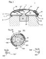
- FIG. 1 shows a color ring 1 together with a (not shown motor).
- An L-shaped outer ring 3 is provided for filter segments 0.7 mm thick. It is an aluminum ring with an outer diameter of 60 mm, which is 1.5 mm wide at its widest point in the radial direction and 2 mm high in the axial direction.
- the metal ring has a level 5, which has a width of 0.5 mm.
- the surface of the shell of the cylinder with a diameter of 58 mm represents a primary adhesive zone 9.
- the annular surface, which is the top of the step 5, forms a secondary adhesive zone 11.
- a recess 13 may be provided in the adhesive can be filled. This also helps to ensure that the segments fit snugly in the corner. In addition, it is avoided that adhesive is pressed out.
- a thin layer of adhesive is applied to the outer ring in the region of the primary or secondary, or both adhesive zones, optionally preferably in the indentation 13.
- the adhesive is preferably not applied along the full length of the groove to minimize stresses through the adhesive that might occur due to thermal expansion of the segments, the adhesive, and the outer ring.
- adhesive may be applied in the form of a broken line or even discrete dots.
- such discrete points lie at the end points of the outer circular arcs of the segments at which two adjacent segments come together.
- the area intended for optical use is interrupted anyway due to the transition between the two segments.
- adhesive is applied only in the region of the secondary adhesive surface 11 and not in the region of the primary adhesive surface. This avoids that, in the case of temperature fluctuations, the adhesive directly exerts shear stresses on the edges of the segments. In this case, it is advantageous to attach the adhesive at a good distance to the end points of the outer circular arc of the segments, for example in the middle.
- the outer ring is placed in a holder 17 for filter segments 15, 15 ', 15 "
- the holder has a recess 19, which has been obtained, for example, via removal of material This recess is suitable for receiving the outer ring in such a way that it has an annular surface after insertion of the outer ring is at the same height as the secondary adhesive zone 11.
- the nikringformige surface of the holder 17 has a smaller inner diameter than the outer diameter of the shaft 23 to be mounted.
- the filter segments 15, 15 ', 15 are brought onto the annular surface of the holder and pushed to the primary gluing zone of the outer ring, and the segments then preferably have substantially no distance from this primary gluing zone 9.
- the segments are preferably arranged spaced apart, for example with the aid of spacer plates.
- the gap between the segments is between 0.01 mm and 0.3 mm, ideally a distance of around 0.05 mm.
- the spacers are used to achieve uniform gap thicknesses 21, 21 '. These gaps help prevent the segments from stressing each other across the radial edges when the color wheel is cooled to -20 ° C or even -40 ° C, and the shrinkage of the shank is greater due to a larger CTE goes as the shrinkage of the segments.
- an adhesive layer is applied to a shaft 23.
- the shaft may include a recess 25 for receiving the adhesive.
- the shaft is inserted into the holder from below and brought into contact with at least one of the segments 15, 15 ', 15 "via the adhesive layer.
- the attachment is preferably not placed on the edges of the segments 15, 15 ', 15 ", but rather on the underside, slightly away from the edges of the segments 15, 15', 15".
- a holder for the shaft 23 could also be used in combination with a thermal adhesive or other adhesive.
- the resulting color ring is removed from the holder and placed in a heating cabinet to cure the component at a temperature equal to or above the operating temperature of the color wheel. This ensures that at high temperature no strain stresses are present in the segments when the ring is not rotating.
- a flat, concentric ring (not shown) or one or a number of concentric annular sectors 27, 29 may be lid-like mounted to additionally fix the filter segments to the outer ring.
- a ring or such ring sectors can in turn be glued to the filter segments.
- a ring sector 27 can also be connected to the outer ring 3 by means of a snap mechanism. This is easily possible if the lateral surface 7 is slightly higher than the filter segments 15, 15 ', 15 "are thick and over this protrudes, as in the FIG. 1 shown.
- a nose 31 may be provided on the outer ring and the ring sector 27 may be shaped to nestle around the outer ring and snap into the edge formed by the nose 31.
- the operating volume of the color wheel is preferably not only a ring sector 27, but a whole snap ring used.
- spacer plates may be permanently provided between the segments in the outer ring.
- the spacer plates are formed of elastic material. It is particularly advantageous if they are provided with a head, which can be positively inserted into the annular recess 13 of the outer ring here. The indentation should then be shaped so that the head of the spacer plates can be pressed into the recess and snaps into it. In this way, the spacer plates are held at the ring and can still be moved along the circumference of the outer ring. This corresponds to the principle of a rail.
- FIG. 2a shows the top view of a color wheel 101 according to an embodiment of the present invention.
- the outer ring 103 has the profile of an interrupted U-shape.
- a section along the line AA 'and Figure 2c shows a cut along the line B-B '.
- the segments 105, 105 ', 105 ", 105" are inserted at the L-shaped areas corresponding to AA' and pushed into the U-shaped areas corresponding to BB '.
- One of the L-shaped areas should be at least as large as the largest of the filter segments 105, 105 ', 105 ", 105"'.
- the filter segments can be inserted radially because they are first connected to the outer ring 103 before being attached to the shaft.
- FIG. 2 additionally shows a possibility for the connection of a shaft with the segments 105, 105 ', 105 ", 105"', without having to use adhesive.
- a part of the shaft 107 has the shape of a quadrilateral.
- the "inner arc" of the segments may be significantly modified.
- the “inner circular arcs” are modified so that the segments, when assembled, rewrite the quadrangular shape of the shaft 107 in a positive fit. Since this is no longer rotationally symmetric, the rotation of the shaft leads directly to the rotation of the segments 105, 105 ', 105 ", 105"'.
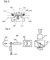
- FIG. 3 shows a cross section of the component FIG. 2 , Only the central part of the color ring 101 is shown. Shown is the shaft 107 as well as two of the filter segments 105 ', 105 "' The shaft has a recess 117 into which the filter segments fit The sidewalls 119 of the recess 117 have a slightly pyramidal shape in this example because of the walls underlying the walls Base is a quadrilateral.
- a thread is provided in the shaft 107, which forms the counterpart to the screw 111 of a cover 109.
- the lid 109 has elastic on its underside Elements 113. These may for example consist of elastic material or have an elastic shape. When the lid 109 is screwed to the shaft, the elastic members 113 press the filter segments down.
- elastic wedges 115 are provided on the lid 109, which slide during insertion along the side walls 119 of the recess 117 and thus press the filter segments radially outward.
- FIG. 4 shows a projector 200.
- a system is suitable for use as a front or rear projector or the like.
- An example of a well-suited application is the television.
- the lamp 202 provides light which is integrated in the integrator 204.
- the integrator 204 may be formed by a tunnel having inwardly facing mirrors.
- the light from the light source 102 is then reflected many times off the walls, forming a homogeneous rectangular light field at the output of the integrator.
- the color wheel 206 is such as to provide the correct color when the spatial light modulator (SLM) 218 is switched in accordance with this color.
- SLM spatial light modulator
- Also shown without reference character is the outer ring on the color wheel 206.
- illumination lenses 208 Downstream from the integrator, illumination lenses 208 are positioned which image the uniform light field from the integrator output to the SLM 218 via a prism 210.
- the spatially modulated light is then sent to the projection lens 214.
- transmissive color wheels The entire description herein has referred to transmissive color wheels. However, the same principle can also be applied to color wheels that function in reflection. For example, if the color characteristic of the segments through Thin-film interference filter is achieved, this is done by selective reflection and transmission. Such a transmissive color wheel is also a reflective color wheel. Some projectors work in such a reflection mode. The principle of the present invention can also be advantageously applied to these color wheels and should therefore be considered within the scope of this invention. In addition, there are color wheels that include not only transmissive segments, but also, for example, black, light-blocking segments.
Landscapes
- Physics & Mathematics (AREA)
- General Physics & Mathematics (AREA)
- Optics & Photonics (AREA)
- Engineering & Computer Science (AREA)
- Multimedia (AREA)
- Signal Processing (AREA)
- Astronomy & Astrophysics (AREA)
- Spectroscopy & Molecular Physics (AREA)
- Optical Filters (AREA)
- Projection Apparatus (AREA)
- Mechanical Light Control Or Optical Switches (AREA)
Claims (2)
- Roue de coupleurs ayant un moteur et un anneau de couleurs (101) arrange sur le moteur, dans laquelle l'anneau de couleurs comporte une tige (107), un support (103) et un certain nombre de segments filtrants (105, 105', 105") qui sont arrangés de manière rigide sur le support (103) et qui sont destinés à être introduits dans un chemin optique ;
dans laquelle la géométrie du support (103) est telle que, pour sa vue de dessus, des anneaux circulaires existent dans la zone dans laquelle s'adapte la vue de dessus et l'anneau circulaire correspondant au contenu de zone minimum définit un rayon extérieur et un rayon intérieur ;
dans laquelle chacun des segments filtrants (105, 105', 105") est transparent et chacun des segments filtrants (105, 105', 105") fait saillie dans le sens radial à l'intérieur du cercle au rayon intérieur afin de contribuer à une zone annulaire transparente qui est adaptée pour être introduite à l'intérieur du chemin lumineux de sorte que, lors de la rotation de l'anneau de couleurs, la zone introduite à l'intérieur du chemin lumineux reste transparente ;
dans laquelle la tige (107) est arrangée sur le moteur et est prévue à des fins de rotation de la roue de couleurs (101) et comporte un axe central autour duquel elle peut être mise en rotation ;
dans laquelle au moins un des segments filtrants (105, 105', 105") est arrangé sur la tige ;
dans laquelle l'arrangement sur la tige (107) relativement a des forces centrifuges est conçu pour être moins rigide que la fixation des segments filtrants (105, 105', 105") sur le support (103) de sorte qu'une rotation de l'anneau de couleurs a un effet de compression sur tous les segments filtrants,
caractérisée en ce que, pour fixer la tige (107) sur les segments filtrants (105,105'), des moyens élastiques (115) sont mis en oeuvre sur la tige pour comprimer les segments dans le sens radial vers l'extérieur. - Roue de couleurs selon a revendication 1, caractérisée en ce que, pour fixer la tige, des moyens mécaniques (109, 111, 113) sont mis en oeuvre sans adhésif.
Applications Claiming Priority (2)
| Application Number | Priority Date | Filing Date | Title |
|---|---|---|---|
| DE102006020648.7A DE102006020648B4 (de) | 2006-05-02 | 2006-05-02 | Verfahren zur Herstellung eines Farbrades |
| PCT/EP2007/002895 WO2007124829A1 (fr) | 2006-05-02 | 2007-03-30 | Roue de couleurs |
Publications (2)
| Publication Number | Publication Date |
|---|---|
| EP2013652A1 EP2013652A1 (fr) | 2009-01-14 |
| EP2013652B1 true EP2013652B1 (fr) | 2011-12-28 |
Family
ID=38235165
Family Applications (1)
| Application Number | Title | Priority Date | Filing Date |
|---|---|---|---|
| EP07723836A Active EP2013652B1 (fr) | 2006-05-02 | 2007-03-30 | Roue de couleurs |
Country Status (8)
| Country | Link |
|---|---|
| US (1) | US20070279779A1 (fr) |
| EP (1) | EP2013652B1 (fr) |
| KR (1) | KR101306561B1 (fr) |
| CN (1) | CN101443685B (fr) |
| AT (1) | ATE539369T1 (fr) |
| DE (1) | DE102006020648B4 (fr) |
| TW (1) | TWI422950B (fr) |
| WO (1) | WO2007124829A1 (fr) |
Families Citing this family (10)
| Publication number | Priority date | Publication date | Assignee | Title |
|---|---|---|---|---|
| US8228626B2 (en) | 2007-03-20 | 2012-07-24 | Oerlikon Trading Ag, Trubbach | Color wheel with individual balancing masses along a guide |
| DE102007013899B4 (de) * | 2007-03-20 | 2024-07-11 | Oerlikon Trading Ag, Trübbach | Verfahren zum Auswuchten eines Farbrades mit individuellen Auswuchtmassen entlang einer Führung |
| CN101359075A (zh) * | 2007-07-30 | 2009-02-04 | 鸿富锦精密工业(深圳)有限公司 | 色轮 |
| DE102011084961A1 (de) * | 2011-10-21 | 2013-04-25 | Osram Gmbh | Leuchtstoffrad, Verfahren zum Herstellen eines Leuchtstoffrads und Beleuchtungsanordnung |
| TWI540377B (zh) * | 2014-01-29 | 2016-07-01 | 台達電子工業股份有限公司 | 光波長轉換器及其適用之光源系統 |
| JP6356526B2 (ja) * | 2014-08-01 | 2018-07-11 | 株式会社日立エルジーデータストレージ | 光モジュールとその製造方法 |
| CN109917611A (zh) * | 2017-12-12 | 2019-06-21 | 深圳光峰科技股份有限公司 | 一种色轮装置及投影设备 |
| JP7279436B2 (ja) * | 2019-03-18 | 2023-05-23 | セイコーエプソン株式会社 | 波長変換素子、光源装置、プロジェクター、及び波長変換素子の製造方法 |
| DE102020122720A1 (de) * | 2019-09-03 | 2021-03-04 | Schott Ag | Ausbalanciertes Konverterfarbrad |
| LU102905B1 (en) * | 2022-01-31 | 2023-07-31 | OroraTech GmbH | Filter assembly and method of manufacturing same |
Citations (1)
| Publication number | Priority date | Publication date | Assignee | Title |
|---|---|---|---|---|
| US5868482A (en) * | 1996-04-30 | 1999-02-09 | Balzers Aktiegesellschaft | Color wheel and picture generation unit with a color wheel |
Family Cites Families (11)
| Publication number | Priority date | Publication date | Assignee | Title |
|---|---|---|---|---|
| JPS6446703A (en) * | 1987-08-17 | 1989-02-21 | Koichi Murata | Three color separating and synthesizing filter |
| US5777694A (en) * | 1995-06-13 | 1998-07-07 | Texas Instruments Incorporated | Color wheel with plastic film filters |
| JPH11295622A (ja) * | 1998-04-10 | 1999-10-29 | Minolta Co Ltd | 照明装置 |
| US6011662A (en) * | 1998-07-01 | 2000-01-04 | Light & Sound Design, Ltd. | Custom color wheel |
| AU2002347124A1 (en) * | 2001-12-20 | 2003-07-09 | Unaxis Balzers Limited | Method of making a rotational optical arrangement and an optical arrangement made by the method |
| US20040066495A1 (en) | 2002-10-04 | 2004-04-08 | Joseph Yu | Color wheel assembly |
| JP4259147B2 (ja) * | 2003-03-13 | 2009-04-30 | カシオ計算機株式会社 | 光源装置及びそれを用いた投影型表示装置 |
| TWI231383B (en) * | 2003-05-12 | 2005-04-21 | Delta Electronics Inc | Filter and color wheel with filter and manufacturing method thereof |
| TWI245157B (en) * | 2003-12-15 | 2005-12-11 | Asia Optical Co Inc | Color wheel |
| KR20060022035A (ko) * | 2004-09-06 | 2006-03-09 | 엘지전자 주식회사 | 투사 광학계 색분리 장치의 먼지 제거 장치 |
| TW200613770A (en) * | 2004-10-26 | 2006-05-01 | Delta Electronics Inc | Color wheel |
-
2006
- 2006-05-02 DE DE102006020648.7A patent/DE102006020648B4/de not_active Expired - Fee Related
-
2007
- 2007-03-30 CN CN200780015691.0A patent/CN101443685B/zh not_active Expired - Fee Related
- 2007-03-30 WO PCT/EP2007/002895 patent/WO2007124829A1/fr not_active Ceased
- 2007-03-30 KR KR1020087027443A patent/KR101306561B1/ko not_active Expired - Fee Related
- 2007-03-30 AT AT07723836T patent/ATE539369T1/de active
- 2007-03-30 EP EP07723836A patent/EP2013652B1/fr active Active
- 2007-04-19 US US11/737,387 patent/US20070279779A1/en not_active Abandoned
- 2007-04-30 TW TW096115227A patent/TWI422950B/zh not_active IP Right Cessation
Patent Citations (1)
| Publication number | Priority date | Publication date | Assignee | Title |
|---|---|---|---|---|
| US5868482A (en) * | 1996-04-30 | 1999-02-09 | Balzers Aktiegesellschaft | Color wheel and picture generation unit with a color wheel |
Also Published As
| Publication number | Publication date |
|---|---|
| WO2007124829A1 (fr) | 2007-11-08 |
| DE102006020648B4 (de) | 2020-06-10 |
| KR101306561B1 (ko) | 2013-09-09 |
| TW200745720A (en) | 2007-12-16 |
| KR20090017511A (ko) | 2009-02-18 |
| EP2013652A1 (fr) | 2009-01-14 |
| ATE539369T1 (de) | 2012-01-15 |
| DE102006020648A1 (de) | 2007-11-08 |
| TWI422950B (zh) | 2014-01-11 |
| CN101443685A (zh) | 2009-05-27 |
| US20070279779A1 (en) | 2007-12-06 |
| CN101443685B (zh) | 2015-01-14 |
Similar Documents
| Publication | Publication Date | Title |
|---|---|---|
| EP2013652B1 (fr) | Roue de couleurs | |
| DE19708949C2 (de) | Farbrad und Bilderzeugungsvorrichtung mit einem Farbrad | |
| US5446591A (en) | Lens mounting for use with liquid lens elements | |
| US20230046945A1 (en) | Fresnel lens mold and manufacturing method therefor, and manufacturing method for fresnel lens | |
| EP0354961A1 (fr) | Collimateur automoule | |
| DE202019101599U1 (de) | Optisches Lichtleiter-Element mit flexibler Schicht | |
| DE19949574A1 (de) | Bildformende Einheit, Vergrößerungseinheit, optische Teile und Bilddarstellungsgerät mit diesen Komponenten | |
| EP2162778B1 (fr) | Objectif de caméra, notamment destiné à être utilisé dans un véhicule automobile, et procédé de fabrication de celui-ci | |
| CH694477A5 (de) | Farbrad und Bilderzeugungsvorrichtung mit einem solchen Farbrad. | |
| DE102018132065A1 (de) | Mikroprojektoren aufweisendes Projektionslichtmodul für einen Kraftfahrzeugscheinwerfer | |
| DE68908064T2 (de) | Gerät zur Befestigung eines optischen Teils, wie einen Filter auf einem Träger. | |
| EP3514582B1 (fr) | Rétroréflecteur élastique | |
| JP2002071923A (ja) | 回折光学素子の製造方法及び回折光学素子、並びに該回折光学素子を有する光学系、該光学系を有する撮影装置と観察装置 | |
| DE102005029296B4 (de) | Farbrad mit selbstjustierten Segmenten | |
| US20110013294A1 (en) | Cemented optical element | |
| EP2062443B1 (fr) | Disque colore | |
| JP4831395B2 (ja) | カラーホイールおよびその製造方法 | |
| US20070229683A1 (en) | Color wheels, assemblies and methods of producing them | |
| DE102015015360A1 (de) | Scheinwerfer für ein Kraftfahrzeug | |
| DE102008062101B4 (de) | Rückblickspiegel für ein Kraftfahrzeug und Verfahren zur Herstellung eines Rückblickspiegels | |
| DE19619021A1 (de) | Verfahren zur Herstellung eines Parabolspiegels | |
| EP1463964A2 (fr) | Element optique structure et sa realisation | |
| EP3612870B1 (fr) | Affichage tête haute | |
| WO1988009546A1 (fr) | Dispositif d'affichage comportant un champ d'affichage et un reseau de lamelles et procede de fabrication | |
| DE19960055A1 (de) | Photoelement für ein Gerät zum Lesen optischer Aufzeichnungsträger und Verfahren zu dessen Herstellung |
Legal Events
| Date | Code | Title | Description |
|---|---|---|---|
| PUAI | Public reference made under article 153(3) epc to a published international application that has entered the european phase |
Free format text: ORIGINAL CODE: 0009012 |
|
| 17P | Request for examination filed |
Effective date: 20081020 |
|
| AK | Designated contracting states |
Kind code of ref document: A1 Designated state(s): AT BE BG CH CY CZ DE DK EE ES FI FR GB GR HU IE IS IT LI LT LU LV MC MT NL PL PT RO SE SI SK TR |
|
| AX | Request for extension of the european patent |
Extension state: AL BA HR MK RS |
|
| RIN1 | Information on inventor provided before grant (corrected) |
Inventor name: MILBOURNE, MICHAEL, JOHN Inventor name: ZUEGER, OTHMAR |
|
| RAP1 | Party data changed (applicant data changed or rights of an application transferred) |
Owner name: OERLIKON TRADING AG, TRUEBBACH |
|
| 17Q | First examination report despatched |
Effective date: 20100128 |
|
| GRAP | Despatch of communication of intention to grant a patent |
Free format text: ORIGINAL CODE: EPIDOSNIGR1 |
|
| DAX | Request for extension of the european patent (deleted) | ||
| GRAS | Grant fee paid |
Free format text: ORIGINAL CODE: EPIDOSNIGR3 |
|
| GRAA | (expected) grant |
Free format text: ORIGINAL CODE: 0009210 |
|
| AK | Designated contracting states |
Kind code of ref document: B1 Designated state(s): AT BE BG CH CY CZ DE DK EE ES FI FR GB GR HU IE IS IT LI LT LU LV MC MT NL PL PT RO SE SI SK TR |
|
| REG | Reference to a national code |
Ref country code: GB Ref legal event code: FG4D Free format text: NOT ENGLISH |
|
| REG | Reference to a national code |
Ref country code: CH Ref legal event code: EP |
|
| REG | Reference to a national code |
Ref country code: AT Ref legal event code: REF Ref document number: 539369 Country of ref document: AT Kind code of ref document: T Effective date: 20120115 |
|
| REG | Reference to a national code |
Ref country code: IE Ref legal event code: FG4D |
|
| REG | Reference to a national code |
Ref country code: DE Ref legal event code: R096 Ref document number: 502007008958 Country of ref document: DE Effective date: 20120308 |
|
| REG | Reference to a national code |
Ref country code: NL Ref legal event code: VDEP Effective date: 20111228 |
|
| PG25 | Lapsed in a contracting state [announced via postgrant information from national office to epo] |
Ref country code: LT Free format text: LAPSE BECAUSE OF FAILURE TO SUBMIT A TRANSLATION OF THE DESCRIPTION OR TO PAY THE FEE WITHIN THE PRESCRIBED TIME-LIMIT Effective date: 20111228 |
|
| LTIE | Lt: invalidation of european patent or patent extension |
Effective date: 20111228 |
|
| PG25 | Lapsed in a contracting state [announced via postgrant information from national office to epo] |
Ref country code: LV Free format text: LAPSE BECAUSE OF FAILURE TO SUBMIT A TRANSLATION OF THE DESCRIPTION OR TO PAY THE FEE WITHIN THE PRESCRIBED TIME-LIMIT Effective date: 20111228 Ref country code: GR Free format text: LAPSE BECAUSE OF FAILURE TO SUBMIT A TRANSLATION OF THE DESCRIPTION OR TO PAY THE FEE WITHIN THE PRESCRIBED TIME-LIMIT Effective date: 20120329 Ref country code: SE Free format text: LAPSE BECAUSE OF FAILURE TO SUBMIT A TRANSLATION OF THE DESCRIPTION OR TO PAY THE FEE WITHIN THE PRESCRIBED TIME-LIMIT Effective date: 20111228 Ref country code: SI Free format text: LAPSE BECAUSE OF FAILURE TO SUBMIT A TRANSLATION OF THE DESCRIPTION OR TO PAY THE FEE WITHIN THE PRESCRIBED TIME-LIMIT Effective date: 20111228 |
|
| PG25 | Lapsed in a contracting state [announced via postgrant information from national office to epo] |
Ref country code: CY Free format text: LAPSE BECAUSE OF FAILURE TO SUBMIT A TRANSLATION OF THE DESCRIPTION OR TO PAY THE FEE WITHIN THE PRESCRIBED TIME-LIMIT Effective date: 20111228 |
|
| REG | Reference to a national code |
Ref country code: IE Ref legal event code: FD4D |
|
| PG25 | Lapsed in a contracting state [announced via postgrant information from national office to epo] |
Ref country code: BG Free format text: LAPSE BECAUSE OF FAILURE TO SUBMIT A TRANSLATION OF THE DESCRIPTION OR TO PAY THE FEE WITHIN THE PRESCRIBED TIME-LIMIT Effective date: 20120328 Ref country code: NL Free format text: LAPSE BECAUSE OF FAILURE TO SUBMIT A TRANSLATION OF THE DESCRIPTION OR TO PAY THE FEE WITHIN THE PRESCRIBED TIME-LIMIT Effective date: 20111228 Ref country code: IE Free format text: LAPSE BECAUSE OF FAILURE TO SUBMIT A TRANSLATION OF THE DESCRIPTION OR TO PAY THE FEE WITHIN THE PRESCRIBED TIME-LIMIT Effective date: 20111228 Ref country code: EE Free format text: LAPSE BECAUSE OF FAILURE TO SUBMIT A TRANSLATION OF THE DESCRIPTION OR TO PAY THE FEE WITHIN THE PRESCRIBED TIME-LIMIT Effective date: 20111228 Ref country code: SK Free format text: LAPSE BECAUSE OF FAILURE TO SUBMIT A TRANSLATION OF THE DESCRIPTION OR TO PAY THE FEE WITHIN THE PRESCRIBED TIME-LIMIT Effective date: 20111228 Ref country code: CZ Free format text: LAPSE BECAUSE OF FAILURE TO SUBMIT A TRANSLATION OF THE DESCRIPTION OR TO PAY THE FEE WITHIN THE PRESCRIBED TIME-LIMIT Effective date: 20111228 Ref country code: IS Free format text: LAPSE BECAUSE OF FAILURE TO SUBMIT A TRANSLATION OF THE DESCRIPTION OR TO PAY THE FEE WITHIN THE PRESCRIBED TIME-LIMIT Effective date: 20120428 |
|
| PG25 | Lapsed in a contracting state [announced via postgrant information from national office to epo] |
Ref country code: RO Free format text: LAPSE BECAUSE OF FAILURE TO SUBMIT A TRANSLATION OF THE DESCRIPTION OR TO PAY THE FEE WITHIN THE PRESCRIBED TIME-LIMIT Effective date: 20111228 Ref country code: PT Free format text: LAPSE BECAUSE OF FAILURE TO SUBMIT A TRANSLATION OF THE DESCRIPTION OR TO PAY THE FEE WITHIN THE PRESCRIBED TIME-LIMIT Effective date: 20120430 Ref country code: PL Free format text: LAPSE BECAUSE OF FAILURE TO SUBMIT A TRANSLATION OF THE DESCRIPTION OR TO PAY THE FEE WITHIN THE PRESCRIBED TIME-LIMIT Effective date: 20111228 |
|
| BERE | Be: lapsed |
Owner name: OERLIKON TRADING AG, TRUBBACH Effective date: 20120331 |
|
| PG25 | Lapsed in a contracting state [announced via postgrant information from national office to epo] |
Ref country code: MC Free format text: LAPSE BECAUSE OF NON-PAYMENT OF DUE FEES Effective date: 20120331 Ref country code: DK Free format text: LAPSE BECAUSE OF FAILURE TO SUBMIT A TRANSLATION OF THE DESCRIPTION OR TO PAY THE FEE WITHIN THE PRESCRIBED TIME-LIMIT Effective date: 20111228 |
|
| PLBE | No opposition filed within time limit |
Free format text: ORIGINAL CODE: 0009261 |
|
| STAA | Information on the status of an ep patent application or granted ep patent |
Free format text: STATUS: NO OPPOSITION FILED WITHIN TIME LIMIT |
|
| PG25 | Lapsed in a contracting state [announced via postgrant information from national office to epo] |
Ref country code: IT Free format text: LAPSE BECAUSE OF FAILURE TO SUBMIT A TRANSLATION OF THE DESCRIPTION OR TO PAY THE FEE WITHIN THE PRESCRIBED TIME-LIMIT Effective date: 20111228 |
|
| 26N | No opposition filed |
Effective date: 20121001 |
|
| REG | Reference to a national code |
Ref country code: DE Ref legal event code: R097 Ref document number: 502007008958 Country of ref document: DE Effective date: 20121001 |
|
| PG25 | Lapsed in a contracting state [announced via postgrant information from national office to epo] |
Ref country code: BE Free format text: LAPSE BECAUSE OF NON-PAYMENT OF DUE FEES Effective date: 20120331 |
|
| PG25 | Lapsed in a contracting state [announced via postgrant information from national office to epo] |
Ref country code: ES Free format text: LAPSE BECAUSE OF FAILURE TO SUBMIT A TRANSLATION OF THE DESCRIPTION OR TO PAY THE FEE WITHIN THE PRESCRIBED TIME-LIMIT Effective date: 20120408 |
|
| REG | Reference to a national code |
Ref country code: AT Ref legal event code: MM01 Ref document number: 539369 Country of ref document: AT Kind code of ref document: T Effective date: 20120330 |
|
| PG25 | Lapsed in a contracting state [announced via postgrant information from national office to epo] |
Ref country code: FI Free format text: LAPSE BECAUSE OF FAILURE TO SUBMIT A TRANSLATION OF THE DESCRIPTION OR TO PAY THE FEE WITHIN THE PRESCRIBED TIME-LIMIT Effective date: 20111228 |
|
| PG25 | Lapsed in a contracting state [announced via postgrant information from national office to epo] |
Ref country code: AT Free format text: LAPSE BECAUSE OF NON-PAYMENT OF DUE FEES Effective date: 20120330 Ref country code: MT Free format text: LAPSE BECAUSE OF FAILURE TO SUBMIT A TRANSLATION OF THE DESCRIPTION OR TO PAY THE FEE WITHIN THE PRESCRIBED TIME-LIMIT Effective date: 20111228 |
|
| PG25 | Lapsed in a contracting state [announced via postgrant information from national office to epo] |
Ref country code: TR Free format text: LAPSE BECAUSE OF FAILURE TO SUBMIT A TRANSLATION OF THE DESCRIPTION OR TO PAY THE FEE WITHIN THE PRESCRIBED TIME-LIMIT Effective date: 20111228 |
|
| PG25 | Lapsed in a contracting state [announced via postgrant information from national office to epo] |
Ref country code: LU Free format text: LAPSE BECAUSE OF NON-PAYMENT OF DUE FEES Effective date: 20120330 |
|
| PG25 | Lapsed in a contracting state [announced via postgrant information from national office to epo] |
Ref country code: HU Free format text: LAPSE BECAUSE OF FAILURE TO SUBMIT A TRANSLATION OF THE DESCRIPTION OR TO PAY THE FEE WITHIN THE PRESCRIBED TIME-LIMIT Effective date: 20070330 |
|
| REG | Reference to a national code |
Ref country code: FR Ref legal event code: PLFP Year of fee payment: 10 |
|
| REG | Reference to a national code |
Ref country code: FR Ref legal event code: PLFP Year of fee payment: 11 |
|
| REG | Reference to a national code |
Ref country code: FR Ref legal event code: PLFP Year of fee payment: 12 |
|
| PGFP | Annual fee paid to national office [announced via postgrant information from national office to epo] |
Ref country code: FR Payment date: 20230323 Year of fee payment: 17 |
|
| PGFP | Annual fee paid to national office [announced via postgrant information from national office to epo] |
Ref country code: GB Payment date: 20230321 Year of fee payment: 17 Ref country code: DE Payment date: 20230328 Year of fee payment: 17 |
|
| PGFP | Annual fee paid to national office [announced via postgrant information from national office to epo] |
Ref country code: CH Payment date: 20230402 Year of fee payment: 17 |
|
| REG | Reference to a national code |
Ref country code: DE Ref legal event code: R119 Ref document number: 502007008958 Country of ref document: DE |
|
| REG | Reference to a national code |
Ref country code: CH Ref legal event code: PL |
|
| GBPC | Gb: european patent ceased through non-payment of renewal fee |
Effective date: 20240330 |
|
| PG25 | Lapsed in a contracting state [announced via postgrant information from national office to epo] |
Ref country code: DE Free format text: LAPSE BECAUSE OF NON-PAYMENT OF DUE FEES Effective date: 20241001 |
|
| PG25 | Lapsed in a contracting state [announced via postgrant information from national office to epo] |
Ref country code: GB Free format text: LAPSE BECAUSE OF NON-PAYMENT OF DUE FEES Effective date: 20240330 |
|
| PG25 | Lapsed in a contracting state [announced via postgrant information from national office to epo] |
Ref country code: FR Free format text: LAPSE BECAUSE OF NON-PAYMENT OF DUE FEES Effective date: 20240331 |
|
| PG25 | Lapsed in a contracting state [announced via postgrant information from national office to epo] |
Ref country code: GB Free format text: LAPSE BECAUSE OF NON-PAYMENT OF DUE FEES Effective date: 20240330 Ref country code: FR Free format text: LAPSE BECAUSE OF NON-PAYMENT OF DUE FEES Effective date: 20240331 Ref country code: DE Free format text: LAPSE BECAUSE OF NON-PAYMENT OF DUE FEES Effective date: 20241001 Ref country code: CH Free format text: LAPSE BECAUSE OF NON-PAYMENT OF DUE FEES Effective date: 20240331 |