EP2014238B1 - Outil chirurgical endoscopique - Google Patents
Outil chirurgical endoscopique Download PDFInfo
- Publication number
- EP2014238B1 EP2014238B1 EP08012122A EP08012122A EP2014238B1 EP 2014238 B1 EP2014238 B1 EP 2014238B1 EP 08012122 A EP08012122 A EP 08012122A EP 08012122 A EP08012122 A EP 08012122A EP 2014238 B1 EP2014238 B1 EP 2014238B1
- Authority
- EP
- European Patent Office
- Prior art keywords
- wire
- operating member
- torsional load
- section
- disposed
- Prior art date
- Legal status (The legal status is an assumption and is not a legal conclusion. Google has not performed a legal analysis and makes no representation as to the accuracy of the status listed.)
- Not-in-force
Links
Images







Classifications
-
- A—HUMAN NECESSITIES
- A61—MEDICAL OR VETERINARY SCIENCE; HYGIENE
- A61B—DIAGNOSIS; SURGERY; IDENTIFICATION
- A61B10/00—Instruments for taking body samples for diagnostic purposes; Other methods or instruments for diagnosis, e.g. for vaccination diagnosis, sex determination or ovulation-period determination; Throat striking implements
- A61B10/02—Instruments for taking cell samples or for biopsy
- A61B10/04—Endoscopic instruments, e.g. catheter-type instruments
-
- A—HUMAN NECESSITIES
- A61—MEDICAL OR VETERINARY SCIENCE; HYGIENE
- A61B—DIAGNOSIS; SURGERY; IDENTIFICATION
- A61B17/00—Surgical instruments, devices or methods
- A61B17/22—Implements for squeezing-off ulcers or the like on inner organs of the body; Implements for scraping-out cavities of body organs, e.g. bones; for invasive removal or destruction of calculus using mechanical vibrations; for removing obstructions in blood vessels, not otherwise provided for
- A61B17/221—Gripping devices in the form of loops or baskets for gripping calculi or similar types of obstructions
-
- A—HUMAN NECESSITIES
- A61—MEDICAL OR VETERINARY SCIENCE; HYGIENE
- A61B—DIAGNOSIS; SURGERY; IDENTIFICATION
- A61B17/00—Surgical instruments, devices or methods
- A61B17/00234—Surgical instruments, devices or methods for minimally invasive surgery
-
- A—HUMAN NECESSITIES
- A61—MEDICAL OR VETERINARY SCIENCE; HYGIENE
- A61B—DIAGNOSIS; SURGERY; IDENTIFICATION
- A61B10/00—Instruments for taking body samples for diagnostic purposes; Other methods or instruments for diagnosis, e.g. for vaccination diagnosis, sex determination or ovulation-period determination; Throat striking implements
- A61B10/02—Instruments for taking cell samples or for biopsy
- A61B2010/0216—Sampling brushes
-
- A—HUMAN NECESSITIES
- A61—MEDICAL OR VETERINARY SCIENCE; HYGIENE
- A61B—DIAGNOSIS; SURGERY; IDENTIFICATION
- A61B17/00—Surgical instruments, devices or methods
- A61B17/22—Implements for squeezing-off ulcers or the like on inner organs of the body; Implements for scraping-out cavities of body organs, e.g. bones; for invasive removal or destruction of calculus using mechanical vibrations; for removing obstructions in blood vessels, not otherwise provided for
- A61B2017/22038—Implements for squeezing-off ulcers or the like on inner organs of the body; Implements for scraping-out cavities of body organs, e.g. bones; for invasive removal or destruction of calculus using mechanical vibrations; for removing obstructions in blood vessels, not otherwise provided for with a guide wire
- A61B2017/22039—Implements for squeezing-off ulcers or the like on inner organs of the body; Implements for scraping-out cavities of body organs, e.g. bones; for invasive removal or destruction of calculus using mechanical vibrations; for removing obstructions in blood vessels, not otherwise provided for with a guide wire eccentric
-
- A—HUMAN NECESSITIES
- A61—MEDICAL OR VETERINARY SCIENCE; HYGIENE
- A61B—DIAGNOSIS; SURGERY; IDENTIFICATION
- A61B17/00—Surgical instruments, devices or methods
- A61B17/28—Surgical forceps
- A61B17/29—Forceps for use in minimally invasive surgery
- A61B2017/2926—Details of heads or jaws
- A61B2017/2927—Details of heads or jaws the angular position of the head being adjustable with respect to the shaft
- A61B2017/2929—Details of heads or jaws the angular position of the head being adjustable with respect to the shaft with a head rotatable about the longitudinal axis of the shaft
-
- A—HUMAN NECESSITIES
- A61—MEDICAL OR VETERINARY SCIENCE; HYGIENE
- A61B—DIAGNOSIS; SURGERY; IDENTIFICATION
- A61B90/00—Instruments, implements or accessories specially adapted for surgery or diagnosis and not covered by any of the groups A61B1/00 - A61B50/00, e.g. for luxation treatment or for protecting wound edges
- A61B90/03—Automatic limiting or abutting means, e.g. for safety
- A61B2090/031—Automatic limiting or abutting means, e.g. for safety torque limiting
-
- A—HUMAN NECESSITIES
- A61—MEDICAL OR VETERINARY SCIENCE; HYGIENE
- A61B—DIAGNOSIS; SURGERY; IDENTIFICATION
- A61B90/00—Instruments, implements or accessories specially adapted for surgery or diagnosis and not covered by any of the groups A61B1/00 - A61B50/00, e.g. for luxation treatment or for protecting wound edges
- A61B90/03—Automatic limiting or abutting means, e.g. for safety
- A61B2090/037—Automatic limiting or abutting means, e.g. for safety with a frangible part, e.g. by reduced diameter
Definitions
- the present invention relates to endoscipic surgical tools which are endoscopically inserted into a body.
- Endoscopic treatment tools such as a biopsy brush provided with synthetic fibers inserted between a stranded wire have been used conventionally in order to sample tissue from a body which is used for medical tests.
- tissue is often sampled by rotating the brush section with a rotary operation of a handle disposed at a proximal end of a wire.
- tissue sampling target sites such as a bile duct have several narrow portions and a friction often exerts between tissue walls and the brush. If the rotary operation above is performed in this case, the wire that rotates though the brush section does not rotate due to the friction, so there is a possibility of breaking the wire upon exerting an excessive torsional load.
- Document WO 2006/100882 A1 concerns a guide wire-type treatment instrument having at its distal end an operation wire with a treatment section and a sheath through which the operation wire is inserted in an advanceable and retractable manner.
- Document US 6,454,717 B1 concerns a concentric catheter drive shaft clutch assembly.
- the clutch assembly operates a drive cable either in a drive mode or a release mode. When a torque applied to the drive cable exceeds a critical magnitude, the clutch assembly prevents further rotation of the drive cable by switching from the drive mode to the release mode.
- the present invention was conceived in view of the above-described circumstances and has as its objective the provision of an endoscipic surgical tool which can be operated safely even when a torsional load is exerted on a wire.
- An endoscopic surgical tool is an endoscopic surgical tool, as defined by independent claim 1, which is inserted into a body endoscopically: the tool includes a wire, a surgical section disposed at a first end of the wire which is used for treatment in the body, an operator section disposed at a second end of the wire which moves in conjunction with the wire so as to rotate by a rotary operation; and the movement of the operating section in conjunction with the wire is released upon exerting more than a predetermined excessive torsional load on the wire.
- the endoscopic surgical tool according to the present invention further includes a brittle portion which is disposed in the operator section side of the wire and breaks with a smallest torsional load which may exerts on the wire, and the brittle portion may break upon exerting more than the predetermined torsional load on the wire.
- the operator section may include a first operating member in which the second end of the wire is fixed and a second operating member which is fixed to the first end of the wire.
- the operator section may include a first operating member in which the second end of the wire is fixed; and a second operating member which is bonded by an adhesive on the first operating member; and the adhesion between the first operating member and the second operating member may be detached upon exerting more than the predetermined torsional load on the wire.
- the operator section may include a first operating member in which the second end of the wire is fixed and a second operating member which is fixed on the first operating member; and the first operating member may include a strain relief portion provided with notches formed along the periphery direction intermittently, the strain relief portion may be ruptured upon exerting more than the predetermined torsional load on the wire.
- the endoscopic surgical tool according to the present invention may further include a holding member which is disposed between the first and second operating members and holds the first and second operating members by friction.
- the endoscopic surgical tool according to the present invention may further include: a first engaging member which is disposed on the first operating member, and a second engaging member which is disposed on the second operating member which fixes the second operating member to the first operating member by engaging the first engaging member; and the engagement between the first and second engaging members may be released upon exerting more than the predetermined torsional load.
- the first operating member may be a tube which includes a notch on its outer surface and the second end of the wire is inserted through the first operating member and exposed to the outside of the first operating member from the notch.
- the second end portion when more than a second predetermined torsional load which is smaller than the predetermined torsional load is exerted to the wire, the second end portion may start to be drawn into the first operating member; and when more than the predetermined torsional load is exerted on the wire, the second end portion may be completely housed in the first operating member so as to stop the movement of the second operating member in conjunction with the wire.
- FIG. 1 is an overall structure of an endoscopic treatment tool 1 of the present embodiment.
- the endoscopic treatment tool 1 includes a wire 2, a surgical section 3 disposed at a distal end of the wire 2, a sheath 4 in which the wire 2 is inserted through, a main body 5 in which the sheath 4 is fixed and an operator section 6 which is disposed at a proximal side of the main body 5.
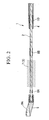
- FIG. 2 is an enlarged diagram in the vicinity of the distal end of the wire 2 (a first end portion).
- the wire 2 is formed by twisting two metal wires together.
- a plurality of synthetic fibers 7 is inserted in the metal wires at the distal end portions of the wire 2 so as to form a brush-shaped surgical section 3.
- Brush markers 8A and 8B made of stainless steel are disposed at both the front and rear portions of the surgical section 3 by caulking, respectively, so that the markers become guides to understand the position of the surgical section 3 when the endoscopic treatment tool 1 is operated under fluoroscopy.
- An edge chip 9 is disposed at the front portion of the surgical section 3 so as to freely rotate relative to the wire 2.
- a through hole 9A where a guide wire which is described later is inserted is disposed at the edge chip 9.
- the sheath 4 is a flexible tube formed of, for example, synthetic resin and a pipe-like index member 10 formed of stainless steel is fixed inside of and near the distal end thereof as shown in FIG. 2 .
- the index member 10 becomes as a marker to understand a position of the distal end of the sheath when the endoscopic treatment tool 1 is operated under fluoroscopy.
- the brush markers 8A, 8B or the index member 10 may be formed of materials such as tantalum which has a high level of visibility under fluoroscopy, instead of stainless steel.
- a colored section 11 is disposed at a predetermined position of the main body 5 side of the sheath 4 as shown in FIG. 1 so that the colored section 11 becomes as a guide to determine the positional relationship of the sheath and the endoscope when the sheath is inserted into the endoscope as described later.
- FIG. 3 is a cross-sectional view of the main body 5.
- the main body includes a main body member 12 and the connecting section 13 disposed at a rear end of the main body member 12.
- the main body member 12 is a substantially pipe-like member made of, for example, synthetic resin and a through hole 12A where the wire 2 is inserted is formed along a central axial line.
- the sheath 4 is fixed by press-fitting at a distal end of the main body member 12.
- An inlet 14 for a contrast agent to be filled is disposed at the upper portion of the main body 5.
- the inlet 14 joins the through hole 12A as shown in FIG. 3 .
- a rubber O-ring 15 is disposed at a pre-determined position of a rear side of the inlet 14 of the through hole 12A so as to maintain water-tightness in order to prevent leakage of the contrast agent filled in the inlet 14 to the rear end of the main body.
- a substantially C-shaped anchor 16 is disposed at a lower portion of the main body member 12 so that an endoscopic treatment tool 1 can be anchored on an endoscope during a procedure.
- a connecting section 13 includes a connector 17 which is disposed at a rear end of the main body member 12, a fitting member 18 where the operator section 6 is engaged and a packing 19 disposed between the connector 17 and the fitting member 18.
- a through hole is provided in each member included in the connecting section 13 along their central axis.
- the fitting member 18 is screw-fitted to an inside of the substantial pipe-like connecting member 17 so that it is structured to allow a movement within a predetermined area in an axial direction.
- a through hole 18A of the fitting member 18 is formed in a tapered shape in which the diameter increases gradually as it approaches a rear end so that it is structured to allow engagement of the operator section 6 as described later.
- the packing 19 is formed of elastic materials such as rubber.
- FIG. 4 is an enlarged view that includes a cross-section through a portion of the operator section 6.
- the operator section 6 includes a pipe 20 (a first operating member) where the wire 2 is inserted and a handle 21 (a second operating member) which is fixed to the pipe 20.
- the pipe 20 is formed of metal and an inserted rear end of the wire 2 (the second end portion) is fixed to the pipe 20 by brazing a filler metal 22 drained into the pipe 20. A proximal end of the pipe 20 is fixed to the handle 21 by welding.
- the handle 21 is made of, for example, synthetic resin.
- the operator section 6 configured as above is inserted into the main body 5 as shown in FIG. 3 , and the pipe 20 and the wire 2 fixed to the pipe 20 can slide inside a through hole of the main body 5 along an axial direction.
- An end portion 21A on the pipe 20 side of the handle 21 is formed in a tapered shape, that is fitted into the through hole 18A of the fitting member 18 shown in FIG. 3 so that it is structured by allowing a positional identification of the surgical section 3.
- a brittle portion 23 is disposed in the vicinity of the rear end of the wire 2.
- the strength of the brittle portion is reduced by tempering so as to break before other portions of the wire 2 when a torsional load is exerted on the wire 2 by a rotary operation with the handle 21.
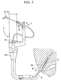
- an endoscope 100 is inserted into a body cavity of a patient with a conventional procedure.
- a distal end of the endoscope 100 is advanced in the vicinity of a duodenal papilla R1, and then a guide wire (not shown) is inserted into an instrument channel from a forceps port 101 of the endoscope 100.
- the guide wire which is protruded from the distal end of the endoscope 100 is advanced into a bile duct R2 from the duodenal papilla R1 and detained under fluoroscopy.
- the sheath 4 is advanced along the guide wire by inserting the rear end of the guide wire into the through hole 9A of the edge chip 9 and inserting it into the forceps port 101, at a position where the surgical section 3 of the endoscopic treatment tool 1 is housed in the sheath 4.
- the main body 5 is fixed to the endoscope 100 by the anchor 16 if necessary.
- tissue is sampled by protruding the surgical section 3 from the sheath 4 and the surgical section 3 is advanced and retracted, or rotated via the operator section 6 after the surgical section 3 of the endoscopic treatment tool 1 is advanced into the bile duct R2.
- extension and retraction of the wire 2 is controlled by advancing the handle 21 and the end portion 21 A is fitted into the through hole 18A of the connecting section 13.
- the fitting member 18 is screwed into the connector 17 so that the packing 19 is pressed by the fitting member 18, and deflects toward the through hole disposed on the packing 19. Therefore, extension and retraction of the wire 2 is controlled by the pipe 20 being sandwiched by the packing 19.
- the surgical section 3 When tissue is harvested at a narrow cavity area such as intrahepatic bile duct, the surgical section 3 may become difficult to rotate due to friction between the surgical section 3 and an inner surface of, for example, a bile duct. At this time, if the handle 21 continues to be rotated, there may be a possibility of breaking the wire 2 by exerting an excessive torsional load than the predetermined amount.
- a user can safely manipulate an extension and retraction movement and removal of the endoscopic treatment tool 1 by holding the wire 2 protruded from the rear portion of the main body 5 in case the wire 2 is broken, since the wire 2 is broken at a brittle portion 23 which has a least strength so as to release the movement of the wire 2 in conjunction to the operator section 6.
- the edge chip 9 where the guide wire is inserted is fitted so as to freely rotate with respect to the wire 2, the wire 2 can be smoothly operated without being twisted even the guide wire is meandered or twisted.
- the brittle portion 23 is disposed by tempering.
- the method for forming the brittle portion is not limited thereto; it is also acceptable to provide the brittle portion by other methods.
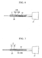
- the brittle portion 23A may be formed by providing a folding portion 24A and 24B in the vicinity of the rear end of the wire 2 so that the brittle portion 23A is more likely to be broken in comparison to other members.
- the brittle portion 23B may be formed by terminating a strand of an element wire 2A and 2B comprised of the wire 2 in the vicinity of the rear end and only the element wire 2A is brazed.
- the operator section includes the pipe 20 and the handle 21, and the wire 2 is fixed to the pipe 20 is described.
- the structure of the present application is not limited thereto, for instance it is also acceptable if the operator section 6 does not include the pipe 20 and the rear end of the wire 2 is directly fixed to the handle 21.
- predetermined amounts of torsional load in which the brittle portion 23 breaks can be adjusted freely by controlling the manufacturing method of the brittle portion 23.
- the brittle portion 23 can be manufactured in the way that the brittle portion 23 becomes more brittle than the surgical section 3 by increasing the degree of tempering the brittle portion 23. In this way, breaking the surgical section 3 by torsional load before the brittle portion 23 can be prevented so as to obtain the same effect of the present invention in the above embodiment.
- An endoscopic treatment tool 31 of the present embodiment differs from the endoscopic treatment tool 1 described above by means of releasing the movement of the operator section in conjunction with the wire due to the manufacturing process of the operator section, in addition to the wire as in the first embodiment, when an excessive torsional load is exerted.
- FIG. 8 is an enlarged cross-sectional diagram of an operator section 32 of the endoscopic treatment tool 31.
- the operator section 32 includes the handle 21 and the pipe 33.
- a notch 34A and 34B are formed along the periphery direction intermittently at the upper and lower portion of the pipe 33, and a strain relief portion 34 is formed.
- the wire 2 and the pipe 33 are fixed to each other by brazing at a more distally positioned area than the strain relief portion 34.
- FIG. 9 is a cross-sectional view as seen from the line A-A in FIG. 8 .
- the strain relief portion 34 is more easily broken compared to other members of the pipe 33 since members of the pipe 33 are only disposed at two places on side walls 34C and 34D as shown in FIG. 9 .
- the size of the notches 34A and 34B is adjusted so as to rupture the strain relief portion 34 with less torsional load than that of the wire 2.
- the number of grandses is not limited to 2, but the number may be one or more than three.
- an endoscopic treatment tool 31 of the present embodiment when the surgical section 3 looses its rotatability due to a friction force against the tissues around, for example, a biliary duct and an excessive torsional load is exerted by a rotary operation of the handle 21, the strain relief portion 34 of the pipe 33 is broken by cutting. Then the movement of the wire 2 in conjunction with the operator section 6 is released hence the torsional load exerted to the wire 2 is absorbed so that breakage of the wire 2 can be prevented.
- the present embodiment describes an example of releasing the movement of the wire 2 in conjunction with the operator section 6 by providing the strain relief portion at the pipe 33, however the manufacturing method of the operator section 6 in order to release the movement of the wire 2 in conjunction with the operator section 6 when an excessive torsional load is exerted on the wire 2 is not limited thereto.
- the pipe 33 and the handle 21 may be bonded by, for example, an adhesive without being fixed by welding.
- the amount and strength of an adhesive may be adjusted so as to detach the bonding between the pipe 33 and the handle 21 in order to release the movement of the operator section 6 in conjunction with the wire 2 when excessive torsional load is exerted on the wire 2.
- the endoscopic treatment tool 41 of the present embodiment differs from the endoscopic treatment tool 1 described above in that a pipe of an operator section and a handle are held by friction force.
- FIG. 10 is an enlarged cross-sectional diagram of an operator section 42 of the endoscopic treatment tool 41. As shown in FIG. 10 , the pipe 43 is inserted into an insertion hole 44B disposed at an end portion 44A of a handle 44, the insertion hole 44B has substantially the same inside diameter as an outside diameter of the pipe 43.
- FIG. 11 is a cross-sectional view seen from the line B-B in FIG. 10 . As shown in FIG. 11 , an outer periphery plane of the pipe 43 is in contact with the holding member 45, and the pipe 43 and the handle 44 are integrated by a friction force generated by the holding member 45. The above holding by the friction force generated by the holding member 45 can be adjusted so as to release with a less torsional load than a load which has a possibility of breaking the wire.
- the movement of the sheath 4 in conjunction with the wire 2 is released by releasing the friction generated by the holding member 45 which holds the pipe 43 and the handle 44. Since breakage of the wire 2 can be prevented without damaging the wire 2 or the operator section 42, an andoscopic treatment tool which is safely operated continuously even when an excessive torsional load is transiently exerted on the wire 2.
- the endoscopic treatment tool 51 of the present embodiment differs from the endoscopic treatment tool 1 of the first embodiment by means of movement of a handle at an operator section in conjunction with a pipe.
- FIG. 12 is an enlarged diagram of an operator section 52 of the endoscopic treatment tool 51.
- An insertion hole of a handle 54 where a pipe 53 is inserted consists of a first half portion 54A of the pipe 53 side and a second half portion 54B with a larger diameter than the first half portion 54A located proximally to an operator.
- FIG. 13 is a cross-sectional view as seen from the line C-C in FIG. 12 .
- a first engaging member 53A is disposed on an outer surface of the pipe 53 by protruding toward the outside of the diameter direction.
- a second engaging member 54C is disposed on an inner surface of the second half portion 54B of the handle 54 by protruding toward the inside of the diameter direction so as to engage the first engaging member 53A.
- the breakage of the wire can be prevented without damaging the wire and operator section as per the endoscopic treatment tool 41 described above. Furthermore, a torsional load exerted on the wire 2 is easily released by releasing the movement of the handle 54 in conjunction with the pipe 53, hence an endoscopic treatment tool which can be operated more safely can be constructed.
- the example of the structure where both the first engaging member 53A and the second engaging member 54C are protruded is described, however the structure is not limited thereto, instead, one of them may be grooved so as to engage the first engaging member 53A and the second engaging member 54C.
- An endoscopic treatment tool 61 of the present embodiment differs from the endoscopic treatment tool 1 described above in that a rear end of a wire is protruded outside of a pipe.
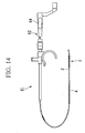
- FIG. 14 is an overall view of the endoscopic treatment tool 61.
- the rear end of the wire 2 is protruded from an operator section 62.
- FIG. 15 is an enlarged view that includes a cross-section of the operator section 62.
- a pipe 63 is fixed on a handle 64 by welding.
- a notch 63A is disposed at a predetermined position on the outer surface of the pipe 63, and the rear end 2A of the wire 2 is protruded out to the pipe 63 from the notch 63A by being bent substantially 90 degrees.
- a movement of an endoscopic treatment tool 61 when in use is described.
- the surgical section 3 housed inside of the sheath 4 is made to advance into the bile duct R2 by the same procedure as shown in FIG. 5 .
- FIGS. 16A to 16C are cross-sectional views as seen from the line D-D in FIG. 15 .
- the notch 63A of the pipe 63 integrated with a handle 64 and the rear end 2A of the wire 2 are not in contact at a normal status as shown in FIG. 16A .
- the operator section 62 moves in conjunction with the wire 2 so as to rotate the surgical section 3 by contacting the notch 63A and the rear end 2A of the wire 2 as shown in FIG. 16B .
- the endoscopic treatment tool 61 of the present embodiment even when the rear end 2A of the wire 2 is contained in the pipe 63, a repeated rotary operation is possible by protruding the rear end 2A from the notch 63A by rotating the handle 64 in an opposite direction. Therefore, the breakage of the wire can be prevented without damaging the wire and the operator section as per the endoscopic treatment tools 41 and 51 described above.
- the surgical tools in which the distal end of the surgical section is a brush are given as examples; the invention is not limited thereto.
- the surgical section may be a conventionally known basket 65 which is formed by twisting a plurality of wires as an example of a modification shown in FIG 17 .
- the present invention can also be applied in any endoscopic treatment tools in which the surgical section is rotated.
- target tissue and organs are not limited in the bile duct as described above; the present invention can be applied in any organ even where rotation of the surgical section may be difficult.
Landscapes
- Health & Medical Sciences (AREA)
- Surgery (AREA)
- Life Sciences & Earth Sciences (AREA)
- General Health & Medical Sciences (AREA)
- Molecular Biology (AREA)
- Veterinary Medicine (AREA)
- Engineering & Computer Science (AREA)
- Biomedical Technology (AREA)
- Heart & Thoracic Surgery (AREA)
- Medical Informatics (AREA)
- Public Health (AREA)
- Animal Behavior & Ethology (AREA)
- Nuclear Medicine, Radiotherapy & Molecular Imaging (AREA)
- Pathology (AREA)
- Radiology & Medical Imaging (AREA)
- Orthopedic Medicine & Surgery (AREA)
- Vascular Medicine (AREA)
- Surgical Instruments (AREA)
- Endoscopes (AREA)
Claims (7)
- Outil chirurgical endoscopique (1, 31) qui est insérable dans un corps par voie endoscopique comprenant :un fil (2) ;une section chirurgicale (3) disposée sur une première extrémité du fil (2) adaptée à être utilisée pour un traitement dans le corps ; etune section d'opérateur (6, 32) disposée sur une deuxième extrémité du fil (2), qui se déplace en conjonction avec le fil (2) de façon à être mise en rotation par une opération de rotation, caractérisé parune partie cassante (23) qui est disposée dans le côté section d'opérateur du fil (2) et est adaptée à casser lorsque plus d'une force de torsion prédéterminée est exercée sur le fil (2) ; dans lequelle mouvement de la section d'opérateur (6, 32) en conjonction avec le fil (2) est interrompu lors de l'exercice de plus de la force de torsion prédéterminée sur le fil (2) par la partie cassante (23) étant cassée.
- Outil chirurgical endoscopique selon la revendication 1, dans lequel
la section d'opérateur inclut un premier élément opérationnel (20) dans lequel la deuxième extrémité du fil est fixée et un deuxième élément opérationnel (21) qui est fixé au premier élément opérationnel. - Outil chirurgical endoscopique selon la revendication 1, dans lequel
la section d'opérateur inclut un premier élément opérationnel (20) dans lequel la deuxième extrémité du fil est fixée et un deuxième élément opérationnel (21) qui est lié par un adhésif sur le premier élément opérationnel et l'adhérence entre le premier élément opérationnel et le deuxième élément opérationnel est adaptée à être rompue par l'exercice de plus de la force de torsion prédéterminée. - Outil chirurgical endoscopique selon la revendication 1, dans lequel
la section d'opérateur inclut un premier élément opérationnel (33) dans lequel la deuxième extrémité du fil est fixée et un deuxième élément opérationnel (21) qui est fixé au premier élément opérationnel ; et
le premier élément opérationnel inclut une partie de réduction de tension (34) prévue avec des entailles (34A, 34B) formées le long d'un sens de la périphérie de façon intermittente au niveau d'une partie supérieure et d'une partie inférieure du premier élément opérationnel (33), la partie de réduction de tension est adaptée à casser par l'exercice de plus d'une force de torsion prédéterminée. - Outil chirurgical endoscopique selon la revendication 2, incluant en outre
un élément de maintien (45) qui est disposé entre le premier et le deuxième éléments opérationnels et est adapté à maintenir le premier et le deuxième éléments opérationnels par frottement. - Outil chirurgical endoscopique selon la revendication 2, comprenant en outre :un premier élément d'engagement (53A) qui est disposé sur le premier élément opérationnel ; etun deuxième élément d'engagement (54C) qui est disposé sur le deuxième élément opérationnel et est adapté à fixer le deuxième élément opérationnel au premier élément opérationnel par engagement du premier élément d'engagement ; dans lequell'engagement entre le premier et le deuxième éléments d'engagement est adapté à être libéré par l'exercice de plus d'une force de torsion prédéterminée.
- Outil chirurgical endoscopique selon la revendication 2, dans lequel
le premier élément opérationnel est un tube (63) qui inclut une entaille (63A) sur sa surface extérieure et la deuxième extrémité du fil est adaptée à être insérée à travers le premier élément opérationnel et exposée à l'extérieur du premier élément opérationnel à partir de l'entaille ;
lorsque plus d'une deuxième force de torsion prédéterminée, qui est plus petite que la force de torsion prédéterminée, est exercée sur le fil, une deuxième partie distale (2A) du fil est adaptée à être tirée dans le premier élément opérationnel ; et
lorsque plus de la force de torsion prédéterminée est exercée sur le fil, la deuxième partie distale est adaptée à être complètement tirée dans le premier élément opérationnel de façon à stopper le mouvement du deuxième élément opérationnel en conjonction avec le fil.
Applications Claiming Priority (1)
| Application Number | Priority Date | Filing Date | Title |
|---|---|---|---|
| US11/775,568 US9451936B2 (en) | 2007-07-10 | 2007-07-10 | Endoscopic surgical tool |
Publications (2)
| Publication Number | Publication Date |
|---|---|
| EP2014238A1 EP2014238A1 (fr) | 2009-01-14 |
| EP2014238B1 true EP2014238B1 (fr) | 2010-12-01 |
Family
ID=39873385
Family Applications (1)
| Application Number | Title | Priority Date | Filing Date |
|---|---|---|---|
| EP08012122A Not-in-force EP2014238B1 (fr) | 2007-07-10 | 2008-07-04 | Outil chirurgical endoscopique |
Country Status (4)
| Country | Link |
|---|---|
| US (1) | US9451936B2 (fr) |
| EP (1) | EP2014238B1 (fr) |
| JP (1) | JP5166994B2 (fr) |
| DE (1) | DE602008003715D1 (fr) |
Families Citing this family (10)
| Publication number | Priority date | Publication date | Assignee | Title |
|---|---|---|---|---|
| WO2012043066A1 (fr) * | 2010-09-29 | 2012-04-05 | テルモ株式会社 | Dispositif médical |
| DE102011110136A1 (de) * | 2011-08-15 | 2013-02-21 | Olympus Winter & Ibe Gmbh | Schaft eines laparoskopischen Instrumentes |
| WO2014049675A1 (fr) * | 2012-09-25 | 2014-04-03 | テルモ株式会社 | Dispositif médical |
| EP2967613B1 (fr) * | 2013-03-11 | 2020-04-22 | Boston Scientific Scimed, Inc. | Poignées de dispositif médical |
| WO2016061297A1 (fr) | 2014-10-15 | 2016-04-21 | Cyrus Acmi, D.B.A. Olympus Surgical Technologies America | Outil chirurgical pour le retrait de calculs néphritiques |
| WO2016166827A1 (fr) * | 2015-04-15 | 2016-10-20 | 国立大学法人九州大学 | Gaine pour outil de traitement pliable et outil de traitement pliable ayant ladite gaine incorporée en son sein |
| JP2017047021A (ja) * | 2015-09-03 | 2017-03-09 | オリンパス株式会社 | 医療用器具の製造方法および医療用器具 |
| US10463245B2 (en) * | 2015-12-21 | 2019-11-05 | Snug Harbor Orthopedics, LLC | Method of using cannula for surgical procedure |
| US11723631B2 (en) * | 2020-04-10 | 2023-08-15 | Orlando Health, Inc. | Brush for non-invasive biopsy |
| WO2023154565A1 (fr) * | 2022-02-14 | 2023-08-17 | Boston Scientific Scimed, Inc. | Dispositifs et procédés d'échantillons de tissu |
Family Cites Families (17)
| Publication number | Priority date | Publication date | Assignee | Title |
|---|---|---|---|---|
| US4653510A (en) * | 1982-03-01 | 1987-03-31 | Accu-Med Corporation | Apparatus for collecting and/or growing protected biological cultures |
| JPS62133926A (ja) | 1985-12-06 | 1987-06-17 | オリンパス光学工業株式会社 | 内視鏡の湾曲操作装置 |
| JPH05142A (ja) | 1991-02-18 | 1993-01-08 | Olympus Optical Co Ltd | 組織採取装置 |
| US5352197A (en) | 1992-03-18 | 1994-10-04 | The Spectranetics Corporation | Turn limiter for a catheter with twistable tip |
| JPH09524A (ja) | 1995-06-21 | 1997-01-07 | Fuji Photo Optical Co Ltd | 超音波プローブ |
| US6022369A (en) | 1998-02-13 | 2000-02-08 | Precision Vascular Systems, Inc. | Wire device with detachable end |
| JP2001258830A (ja) | 2000-03-17 | 2001-09-25 | Asahi Optical Co Ltd | 内視鏡用操作ワイヤーの端末形成方法 |
| JP2001269349A (ja) | 2000-03-23 | 2001-10-02 | Fuji Photo Optical Co Ltd | 内視鏡用処置具 |
| US6454717B1 (en) | 2000-04-13 | 2002-09-24 | Scimed Life Systems, Inc. | Concentric catheter drive shaft clutch |
| JP2002253562A (ja) | 2001-03-02 | 2002-09-10 | Sumitomo Bakelite Co Ltd | 医療用処置具 |
| US20040260201A1 (en) | 2003-06-23 | 2004-12-23 | Mueller Richard L. | Cytology brush with releasable end portion |
| JP2006263159A (ja) * | 2005-03-24 | 2006-10-05 | Olympus Corp | 内視鏡用処置具 |
| US7722636B2 (en) * | 2005-11-30 | 2010-05-25 | Codman & Shurtleff, Inc. | Embolic device delivery system with torque fracture characteristic |
| WO2007070797A2 (fr) * | 2005-12-13 | 2007-06-21 | Cordis Development Corporation | Actionneur de detachement a utiliser avec des systemes de deploiement de dispositif medical |
| JP4160608B2 (ja) * | 2006-08-03 | 2008-10-01 | オリンパスメディカルシステムズ株式会社 | 内視鏡用処置具 |
| US20080077046A1 (en) * | 2006-08-24 | 2008-03-27 | Cytyc Corporation | Snap-off specimen collection device |
| US20110021950A1 (en) * | 2009-07-22 | 2011-01-27 | Father Judge Apostolic Land Company, LLC | Cell collector |
-
2007
- 2007-07-10 US US11/775,568 patent/US9451936B2/en not_active Expired - Fee Related
-
2008
- 2008-06-26 JP JP2008167348A patent/JP5166994B2/ja not_active Expired - Fee Related
- 2008-07-04 DE DE602008003715T patent/DE602008003715D1/de active Active
- 2008-07-04 EP EP08012122A patent/EP2014238B1/fr not_active Not-in-force
Also Published As
| Publication number | Publication date |
|---|---|
| DE602008003715D1 (de) | 2011-01-13 |
| EP2014238A1 (fr) | 2009-01-14 |
| US9451936B2 (en) | 2016-09-27 |
| JP5166994B2 (ja) | 2013-03-21 |
| JP2009018160A (ja) | 2009-01-29 |
| US20090018469A1 (en) | 2009-01-15 |
Similar Documents
| Publication | Publication Date | Title |
|---|---|---|
| EP2014238B1 (fr) | Outil chirurgical endoscopique | |
| CN106999001B (zh) | 具有可选择性弯折的轴杆和选择性弯折该轴杆并且当轴杆弯折时处于张紧中的缆线的手术工具 | |
| EP2123225B1 (fr) | Dispositif d'endoscope | |
| JP5308151B2 (ja) | リード線摘出装置 | |
| EP0746242B1 (fr) | Etrier rotatif pour un instrument microchirurgical flexible | |
| CN101370434B (zh) | 内窥镜系统和医疗器械 | |
| EP2386255B1 (fr) | Instrument de traitement d'endoscope | |
| EP1317214B1 (fr) | Dispositif medical de retrait a effraction minimale | |
| US8523879B1 (en) | Stone retriever for flexible endoscopes having small diameter working channels | |
| US20250151987A1 (en) | Endoscope treatment tool and endoscope system | |
| JP2007301360A (ja) | 処置具挿脱用補助装置 | |
| WO1997043956A1 (fr) | Forceps pour biopsie endoscopique avec ressort a force constante maintenant les machoires fermees | |
| JP2008173472A (ja) | 医療装置、内視鏡用処置具、及び内視鏡装置 | |
| CN101116606A (zh) | 内窥镜用处理器具 | |
| EP2415408B1 (fr) | Dispositif de traitement | |
| JP4554034B2 (ja) | 医療用ガイドワイヤ | |
| CN106999193B (zh) | 内窥镜用处置器具 | |
| KR20160000681A (ko) | 의료용 스네어장치 | |
| JP6389683B2 (ja) | 医療用デバイス | |
| US12419621B2 (en) | Device, systems, and methods for grasping tissue at a muscular level | |
| EP4704665A1 (fr) | Dispositifs, systèmes et procédés d'articulation et/ou de rétroflexion d'un dispositif médical | |
| JP2004261431A (ja) | 内視鏡 | |
| EP4652941A2 (fr) | Attache de surscope avec mécanisme souple | |
| JP2026502599A (ja) | 自動切糸結紮器 | |
| CN116636921A (zh) | 处置器具 |
Legal Events
| Date | Code | Title | Description |
|---|---|---|---|
| PUAI | Public reference made under article 153(3) epc to a published international application that has entered the european phase |
Free format text: ORIGINAL CODE: 0009012 |
|
| AK | Designated contracting states |
Kind code of ref document: A1 Designated state(s): AT BE BG CH CY CZ DE DK EE ES FI FR GB GR HR HU IE IS IT LI LT LU LV MC MT NL NO PL PT RO SE SI SK TR |
|
| AX | Request for extension of the european patent |
Extension state: AL BA MK RS |
|
| 17P | Request for examination filed |
Effective date: 20090310 |
|
| 17Q | First examination report despatched |
Effective date: 20090415 |
|
| AKX | Designation fees paid |
Designated state(s): DE FR GB IE |
|
| GRAP | Despatch of communication of intention to grant a patent |
Free format text: ORIGINAL CODE: EPIDOSNIGR1 |
|
| GRAS | Grant fee paid |
Free format text: ORIGINAL CODE: EPIDOSNIGR3 |
|
| GRAA | (expected) grant |
Free format text: ORIGINAL CODE: 0009210 |
|
| AK | Designated contracting states |
Kind code of ref document: B1 Designated state(s): DE FR GB IE |
|
| REG | Reference to a national code |
Ref country code: GB Ref legal event code: FG4D |
|
| REG | Reference to a national code |
Ref country code: IE Ref legal event code: FG4D |
|
| REF | Corresponds to: |
Ref document number: 602008003715 Country of ref document: DE Date of ref document: 20110113 Kind code of ref document: P |
|
| PLBE | No opposition filed within time limit |
Free format text: ORIGINAL CODE: 0009261 |
|
| STAA | Information on the status of an ep patent application or granted ep patent |
Free format text: STATUS: NO OPPOSITION FILED WITHIN TIME LIMIT |
|
| 26N | No opposition filed |
Effective date: 20110902 |
|
| REG | Reference to a national code |
Ref country code: DE Ref legal event code: R097 Ref document number: 602008003715 Country of ref document: DE Effective date: 20110902 |
|
| PGFP | Annual fee paid to national office [announced via postgrant information from national office to epo] |
Ref country code: IE Payment date: 20140710 Year of fee payment: 7 |
|
| PGFP | Annual fee paid to national office [announced via postgrant information from national office to epo] |
Ref country code: FR Payment date: 20140708 Year of fee payment: 7 Ref country code: GB Payment date: 20140702 Year of fee payment: 7 |
|
| REG | Reference to a national code |
Ref country code: DE Ref legal event code: R082 Ref document number: 602008003715 Country of ref document: DE Representative=s name: WUESTHOFF & WUESTHOFF, PATENTANWAELTE PARTG MB, DE Ref country code: DE Ref legal event code: R081 Ref document number: 602008003715 Country of ref document: DE Owner name: OLYMPUS CORPORATION, JP Free format text: FORMER OWNER: OLYMPUS MEDICAL SYSTEMS CORP., TOKYO, JP |
|
| GBPC | Gb: european patent ceased through non-payment of renewal fee |
Effective date: 20150704 |
|
| REG | Reference to a national code |
Ref country code: IE Ref legal event code: MM4A |
|
| PG25 | Lapsed in a contracting state [announced via postgrant information from national office to epo] |
Ref country code: GB Free format text: LAPSE BECAUSE OF NON-PAYMENT OF DUE FEES Effective date: 20150704 |
|
| REG | Reference to a national code |
Ref country code: FR Ref legal event code: ST Effective date: 20160331 |
|
| PG25 | Lapsed in a contracting state [announced via postgrant information from national office to epo] |
Ref country code: FR Free format text: LAPSE BECAUSE OF NON-PAYMENT OF DUE FEES Effective date: 20150731 |
|
| PG25 | Lapsed in a contracting state [announced via postgrant information from national office to epo] |
Ref country code: IE Free format text: LAPSE BECAUSE OF NON-PAYMENT OF DUE FEES Effective date: 20150704 |
|
| P01 | Opt-out of the competence of the unified patent court (upc) registered |
Effective date: 20230528 |
|
| PGFP | Annual fee paid to national office [announced via postgrant information from national office to epo] |
Ref country code: DE Payment date: 20230719 Year of fee payment: 16 |
|
| REG | Reference to a national code |
Ref country code: DE Ref legal event code: R119 Ref document number: 602008003715 Country of ref document: DE |
|
| PG25 | Lapsed in a contracting state [announced via postgrant information from national office to epo] |
Ref country code: DE Free format text: LAPSE BECAUSE OF NON-PAYMENT OF DUE FEES Effective date: 20250201 |