EP2014331B1 - Dispositif d'application intracorporelle des dispositifs médicaux - Google Patents
Dispositif d'application intracorporelle des dispositifs médicaux Download PDFInfo
- Publication number
- EP2014331B1 EP2014331B1 EP08012342A EP08012342A EP2014331B1 EP 2014331 B1 EP2014331 B1 EP 2014331B1 EP 08012342 A EP08012342 A EP 08012342A EP 08012342 A EP08012342 A EP 08012342A EP 2014331 B1 EP2014331 B1 EP 2014331B1
- Authority
- EP
- European Patent Office
- Prior art keywords
- winding insert
- application tube
- winding
- insert
- medical
- Prior art date
- Legal status (The legal status is an assumption and is not a legal conclusion. Google has not performed a legal analysis and makes no representation as to the accuracy of the status listed.)
- Not-in-force
Links
- 206010019909 Hernia Diseases 0.000 claims abstract description 6
- 238000004804 winding Methods 0.000 claims description 100
- 238000003780 insertion Methods 0.000 claims description 6
- 230000037431 insertion Effects 0.000 claims description 6
- 238000001356 surgical procedure Methods 0.000 abstract description 6
- 238000005096 rolling process Methods 0.000 abstract description 3
- 206010052428 Wound Diseases 0.000 description 19
- 208000027418 Wounds and injury Diseases 0.000 description 19
- 210000003195 fascia Anatomy 0.000 description 3
- 229920003023 plastic Polymers 0.000 description 3
- 239000004033 plastic Substances 0.000 description 3
- 239000007943 implant Substances 0.000 description 2
- 206010017815 Gastric perforation Diseases 0.000 description 1
- 208000029836 Inguinal Hernia Diseases 0.000 description 1
- 201000010829 Spina bifida Diseases 0.000 description 1
- 208000006097 Spinal Dysraphism Diseases 0.000 description 1
- 238000012084 abdominal surgery Methods 0.000 description 1
- 238000002674 endoscopic surgery Methods 0.000 description 1
- 230000001605 fetal effect Effects 0.000 description 1
- 230000002496 gastric effect Effects 0.000 description 1
- KHYBPSFKEHXSLX-UHFFFAOYSA-N iminotitanium Chemical compound [Ti]=N KHYBPSFKEHXSLX-UHFFFAOYSA-N 0.000 description 1
- 206010022694 intestinal perforation Diseases 0.000 description 1
- 239000000463 material Substances 0.000 description 1
- 238000000034 method Methods 0.000 description 1
- 229910001000 nickel titanium Inorganic materials 0.000 description 1
Images


Classifications
-
- A—HUMAN NECESSITIES
- A61—MEDICAL OR VETERINARY SCIENCE; HYGIENE
- A61B—DIAGNOSIS; SURGERY; IDENTIFICATION
- A61B17/00—Surgical instruments, devices or methods
- A61B17/34—Trocars; Puncturing needles
- A61B17/3468—Trocars; Puncturing needles for implanting or removing devices, e.g. prostheses, implants, seeds, wires
-
- A—HUMAN NECESSITIES
- A61—MEDICAL OR VETERINARY SCIENCE; HYGIENE
- A61F—FILTERS IMPLANTABLE INTO BLOOD VESSELS; PROSTHESES; DEVICES PROVIDING PATENCY TO, OR PREVENTING COLLAPSING OF, TUBULAR STRUCTURES OF THE BODY, e.g. STENTS; ORTHOPAEDIC, NURSING OR CONTRACEPTIVE DEVICES; FOMENTATION; TREATMENT OR PROTECTION OF EYES OR EARS; BANDAGES, DRESSINGS OR ABSORBENT PADS; FIRST-AID KITS
- A61F15/00—Auxiliary appliances for wound dressings; Dispensing containers for dressings or bandages
- A61F15/005—Bandage applicators
-
- A—HUMAN NECESSITIES
- A61—MEDICAL OR VETERINARY SCIENCE; HYGIENE
- A61B—DIAGNOSIS; SURGERY; IDENTIFICATION
- A61B17/00—Surgical instruments, devices or methods
- A61B17/56—Surgical instruments or methods for treatment of bones or joints; Devices specially adapted therefor
- A61B17/58—Surgical instruments or methods for treatment of bones or joints; Devices specially adapted therefor for osteosynthesis, e.g. bone plates, screws or setting implements
- A61B17/88—Osteosynthesis instruments; Methods or means for implanting or extracting internal or external fixation devices
- A61B17/8861—Apparatus for manipulating flexible wires or straps
-
- A—HUMAN NECESSITIES
- A61—MEDICAL OR VETERINARY SCIENCE; HYGIENE
- A61F—FILTERS IMPLANTABLE INTO BLOOD VESSELS; PROSTHESES; DEVICES PROVIDING PATENCY TO, OR PREVENTING COLLAPSING OF, TUBULAR STRUCTURES OF THE BODY, e.g. STENTS; ORTHOPAEDIC, NURSING OR CONTRACEPTIVE DEVICES; FOMENTATION; TREATMENT OR PROTECTION OF EYES OR EARS; BANDAGES, DRESSINGS OR ABSORBENT PADS; FIRST-AID KITS
- A61F2/00—Filters implantable into blood vessels; Prostheses, i.e. artificial substitutes or replacements for parts of the body; Appliances for connecting them with the body; Devices providing patency to, or preventing collapsing of, tubular structures of the body, e.g. stents
- A61F2/0063—Implantable repair or support meshes, e.g. hernia meshes
- A61F2002/0072—Delivery tools therefor
Definitions
- the invention relates to a device for the intracorporeal application of medical aids, in particular plastics and wound dressings, with a hollow application tube for introducing the medical device into the operating area.
- EP 0 625 334 A1 US 5,464,403 . US 5,814,058 . US 5,263,969 .
- EP 0 581 036 A1 and WO 2007/056 297 A2 reveal applicators with sliding winding inserts without latching steps.
- the invention is based on the object to provide a device for intracorporeal application of medical aids, which ensures simple handling a secure application of the medical aid in the operation area.
- winding insert insertable into the application tube By using the winding insert insertable into the application tube according to the invention, it is possible for the first time to dispense with manual rolling or folding of the medical aid to be applied.
- the winding insert together with the wound on the winding insert medical aids is also displaced in the longitudinal direction of the application tube to move the medical aid to the operating area out.
- the winding insert and the application tube can be rotated relative to one another around the longitudinal axis of the instrument when they are placed in one another. This mutual rotatability of the components facilitates the winding and unwinding of the medical aid on the winding insert or from the winding insert down.
- the medical device on the winding insert can be fixed, for example by forming a slot in the winding insert for receiving an end of the medical device.
- the setting of the medical aid on the winding insert via a formed in the winding insert through slot, in which the medical aid is used.
- the winding insert at least in the area receiving the medical aid, is designed as a wire pin which can be inserted into the application tube, preferably made of a Ni-Ti material.
- the winding insert can be inserted into the application tube in predetermined latching steps in the axial direction. These rest stops provide predetermined insertion depths of the winding insert into the application tube, for example, an insertion and an application position, and thus enable a secure and uniform operation of the device.
- At least one opening extending in the axial direction is formed in the application tube for introducing the medical aid.
- This window-like opening in the application tube makes it possible to fix the medical aid on the winding insert when the winding insert is inserted into the application tube.
- the medical device is guided through the opening into the interior of the application tube and fixed, for example, with one end in the slot of the winding insert.
- the medical aid is drawn into the application tube and wound around the winding insert.
- two mutually approximately, axially extending openings are formed in the application tube.
- this embodiment is advantageous because it allows a faster winding of the medical device on the winding insert.
- the medical device is guided through an opening in the interior of the application tube and pulled through the continuous slot of the winding insert until the medical device emerges from the opposite opening of the application tube again from the application tube.
- the medical aid is drawn into the application tube and wound double-wound around the winding insert.
- the operation of the application tube and the winding insert, in particular in the mutual rotation of the components, according to the invention can be facilitated by the fact that a handle is arranged at the proximal end of the application tube and / or the winding insert.
- the medical aid is a mesh for hernia surgery or the like.
- meshes or mesh implants consisting of the body's own or exogenous tissue are used to bridge the corresponding fascia gap.
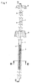
- the in the pictures Fig. 1 and 2 illustrated device for intracorporeal application of medical aids consists essentially of a hollow outer application tube 1 and an insertable into the application tube 1 and slidable in the longitudinal direction of the application tube 1 winding insert.
- the winding insert 2 for holding receiving a medical device 3, which is introduced via the application tube 1 in the operation area.
- the medical device 3 is fixed to the winding insert 2 and wound on the winding insert 2, before the medical device 3 is subsequently fed through the application tube 1 into the surgical area in this state wound onto the winding insert 2.
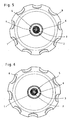
- the setting of the medical device 3 on the winding insert 2 takes place in the in Fig. 3 illustrated first embodiment of a formed in the winding insert 2 through slot 4 through which the medical device 3 is pushed through until the medical device 3 protrudes on both sides, preferably of equal length, from the slot 4.
- By turning the winding insert 2 can now be the medical device 3 double-wound on the winding insert 2, as shown schematically in FIG Fig. 5 is shown.
- the setting of the medical device 3 on the winding insert 2 is such that in the winding insert 2, a slot 5 is formed, in which one end of the medical device 3 can be inserted.
- the winding insert 2 can now be the medical aid 3 catchy wind on the winding insert 2, as shown schematically in FIG Fig. 6 is shown.
- the medical aids 3 can be, for example, wound dressings or plastics which are introduced in a collapsed form into the operating area and are first spread out in place on the operating area and applied to the corresponding application site.
- One area of application for this device is, for example, hernia surgeries in which the medical device is designed as a mesh or mesh implant consisting of the body's own or exogenous tissue in order to bridge the corresponding fascia gap.
- window-like opening 6 is formed, through which the medical device 3 can be inserted for fixing the winding insert 2 in the application tube 1, as in Fig. 1 is shown.
- the window-like opening 6 is formed as a gap 6, but other embodiments are possible, which allow the medical device 3 to insert the winding insert 2 in the application tube 1 to introduce.
- Fig. 4 and 6 illustrated embodiment in which the medical device 3 is wrapped around the winding insert 2 catchy, it is sufficient to form only a gap 6 in the application tube 1.
- the in the pictures Fig. 4 and 6 differ in terms of formed in the winding insert 2 slots 4 and 5. While according to Fig. 4 in the winding insert 2, only one slot 5 is formed, in which one end of the medical device 3 can be inserted, is in accordance with the embodiment Fig. 6 formed in the winding insert 2, a continuous slot 4, through which the medical device 3 can be pushed.
- This embodiment offers the medical aid 3 fixed to the winding insert 2 better hold than the use of the non-continuous slot 5.
- the winding of the thus defined on the winding insert 2 medical device 3 on the winding insert 2 is carried out subsequently by rotating the winding insert 2 and / or the application tube 1 to the instrument longitudinal axis 7, wherein for the case that both components 1 and 2 are rotated, the application tube. 1 and the winding insert 2 must be rotated in opposite directions.
- the medical aid 3 fixed to the winding insert 2 is pulled into the application tube 1 and wrapped in layers around the winding insert 2.
- the winding insert 2 is designed as a wire pin reducing the diameter of the winding insert 2 at least in the area receiving the medical aid 3, as shown in the figure Fig. 2 can be seen.
- Deviating from the illustrated shape of the wire pin with a circular cross section, of course, other cross-sectional shapes are executable.
- the outer diameter of the winding insert 2 substantially corresponds to the inner diameter of the application tube 1, to ensure a good and tilt-free guidance of the winding insert 2 in the application tube 1.
- each locking step 9 corresponds to a certain insertion depth of the winding insert 2 in the application tube 1 and marks a corresponding operation.
- the medical device 3 is subsequently fixed to the winding insert 2, for example by passage through the continuous slot 4, as shown in FIG Fig. 2 is shown. Subsequently, the winding insert 2 and / or the application tube 1 are rotated relative to each other about the instrument longitudinal axis 7, whereby the medical aid is drawn into the application tube 1 and winds up on the winding insert 2.
- the winding insert 2 provided with the wound-up medical device 3 is pushed further into the application tube 1 in the distal direction until a second latching step 9 is reached, in which the medical aid 3 is arranged inside the application tube 1 and not again over the at least one gap 6 of the application tube 1 can be unwound from the winding insert 2.
- the application tube 1 together with the inserted winding insert 2, for example via a trocar sleeve in the operating area introduced.
- the winding insert 2 is now pressed into the application tube 2 up to the third latching step 9, in which the winding insert 2 wrapped with the medical device 3 to be applied emerges distally from the application tube 1 again.
- the medical device 3 can be detected, for example by means of a forceps.
- the medical aid 3 can now be easily and safely unwound in place from the winding insert 2 and applied to the surgical site to be supplied.
- Such a device designed for intracorporeal application of medical aids 3 is characterized in that it ensures a safe and gentle transport of the medical device 3 to be applied to the surgical site with a simple structure and simple handling.
Landscapes
- Health & Medical Sciences (AREA)
- Life Sciences & Earth Sciences (AREA)
- Animal Behavior & Ethology (AREA)
- General Health & Medical Sciences (AREA)
- Veterinary Medicine (AREA)
- Engineering & Computer Science (AREA)
- Biomedical Technology (AREA)
- Heart & Thoracic Surgery (AREA)
- Public Health (AREA)
- Surgery (AREA)
- Pathology (AREA)
- Molecular Biology (AREA)
- Medical Informatics (AREA)
- Nuclear Medicine, Radiotherapy & Molecular Imaging (AREA)
- Epidemiology (AREA)
- Vascular Medicine (AREA)
- Surgical Instruments (AREA)
- Prostheses (AREA)
- Accommodation For Nursing Or Treatment Tables (AREA)
- Orthopedics, Nursing, And Contraception (AREA)
- Media Introduction/Drainage Providing Device (AREA)
- Medicinal Preparation (AREA)
Claims (10)
- Appareillage pour l'application intracorporelle de dispositifs médicaux, notamment de greffes plastiques et de pansements, comprenant un tube d'application creux (1) destiné à introduire le dispositif médical (3) dans la région opératoire, ainsi qu'un module d'enroulement (2) qui peut être inséré dans le tube d'application creux (1) et peut coulisser dans la direction longitudinale du tube d'application (1), et sur lequel peut être enroulé le dispositif médical (3) à appliquer, caractérisé en ce que le module d'enroulement (2) peut être inséré dans le tube d'application (1) selon des gradins d'encliquetage (9) prédéfinis dans la direction axiale.
- Appareillage selon la revendication 1, caractérisé en ce que le module d'enroulement (2) et le tube d'application (1) peuvent, dans l'état où ils sont insérés l'un dans l'autre, être tournés l'un par rapport à l'autre autour de l'axe longitudinal (7) de l'instrument.
- Appareillage selon la revendication 1 ou la revendication 2, caractérisé en ce que le dispositif médical (3) peut être fixé au module d'enroulement (2).
- Appareillage selon la revendication 3, caractérisé en ce que dans le module d'enroulement (2) est réalisée une fente (5) destinée à recevoir une extrémité du dispositif médical (3).
- Appareillage selon la revendication 3, caractérisé en ce que dans le module d'enroulement (2) est réalisée une fente traversante (4) destinée à recevoir le dispositif médical (3).
- Appareillage selon l'une des revendications 1 à 5, caractérisé en ce que le module d'enroulement (2) est réalisé, au moins dans la zone recevant le dispositif médical (3), en tant que broche filaire pouvant être insérée dans le tube d'application (1).
- Appareillage selon l'une des revendications 1 à 6, caractérisé en ce que dans le tube d'application (1) est réalisée au moins une ouverture (6) s'étendant dans la direction axiale et destinée à l'introduction du dispositif médical (3).
- Appareillage selon la revendication 7, caractérisé en ce que dans le tube d'application (1) sont réalisées deux ouvertures (6) sensiblement opposées l'une à l'autre et s'étendant dans la direction axiale.
- Appareillage selon l'une des revendications 1 à 8, caractérisé en ce qu'à l'extrémité proximale du tube d'application (1) et/ou du module d'enroulement (2), est agencée une poignée (8).
- Appareillage selon l'une des revendications 1 à 9, caractérisé en ce que le dispositif médical (3) est un filet prothétique en matière plastique pour une opération de hernie ou similaire.
Applications Claiming Priority (1)
| Application Number | Priority Date | Filing Date | Title |
|---|---|---|---|
| DE102007032482A DE102007032482A1 (de) | 2007-07-12 | 2007-07-12 | Vorrichtung zur intrakorporalen Applikation medizinischer Hilfsmittel |
Publications (3)
| Publication Number | Publication Date |
|---|---|
| EP2014331A2 EP2014331A2 (fr) | 2009-01-14 |
| EP2014331A3 EP2014331A3 (fr) | 2009-01-21 |
| EP2014331B1 true EP2014331B1 (fr) | 2010-03-10 |
Family
ID=39865043
Family Applications (1)
| Application Number | Title | Priority Date | Filing Date |
|---|---|---|---|
| EP08012342A Not-in-force EP2014331B1 (fr) | 2007-07-12 | 2008-07-09 | Dispositif d'application intracorporelle des dispositifs médicaux |
Country Status (4)
| Country | Link |
|---|---|
| US (1) | US8864779B2 (fr) |
| EP (1) | EP2014331B1 (fr) |
| AT (1) | ATE460202T1 (fr) |
| DE (2) | DE102007032482A1 (fr) |
Families Citing this family (2)
| Publication number | Priority date | Publication date | Assignee | Title |
|---|---|---|---|---|
| US9220586B2 (en) | 2012-09-28 | 2015-12-29 | Covidien Lp | Surgical implant and applicator |
| US10433018B2 (en) * | 2017-03-06 | 2019-10-01 | Tribune Broadcasting Company, Llc | Video production system with dynamic character generator output |
Family Cites Families (19)
| Publication number | Priority date | Publication date | Assignee | Title |
|---|---|---|---|---|
| US5147316A (en) * | 1990-11-19 | 1992-09-15 | Castillenti Thomas A | Laparoscopic trocar with self-locking port sleeve |
| US5376376A (en) * | 1992-01-13 | 1994-12-27 | Li; Shu-Tung | Resorbable vascular wound dressings |
| US5263969A (en) * | 1992-04-17 | 1993-11-23 | Phillips Edward H | Tool for the laparoscopic introduction of a mesh prosthesis |
| US6312442B1 (en) * | 1992-06-02 | 2001-11-06 | General Surgical Innovations, Inc. | Method for developing an anatomic space for laparoscopic hernia repair |
| US5304187A (en) * | 1992-06-30 | 1994-04-19 | United States Surgical Corporation | Surgical element deployment apparatus |
| US5464403A (en) * | 1992-10-29 | 1995-11-07 | General Surgical Innovations, Inc. | Placement tool and method for laparoscopic hernia repair |
| US5814058A (en) * | 1993-03-05 | 1998-09-29 | Innerdyne, Inc. | Method and apparatus employing conformable sleeve for providing percutaneous access |
| DE69419660T2 (de) * | 1993-05-21 | 1999-12-30 | Ethicon, Issy Les Moulineaux | Endoskopische Befestigungseinrichtung für Prothese aus Weichgewebe |
| AU686206B2 (en) * | 1993-07-12 | 1998-02-05 | Regents Of The University Of California, The | Soft tissue augmentation apparatus |
| US5591207A (en) * | 1995-03-30 | 1997-01-07 | Linvatec Corporation | Driving system for inserting threaded suture anchors |
| AU6769098A (en) * | 1997-03-20 | 1998-10-12 | Focal, Inc. | Biodegradable tissue retractor |
| US6419639B2 (en) * | 1999-08-05 | 2002-07-16 | National Institute Of Health | Laparoscopic SAC holder assembly |
| ES2284836T3 (es) * | 2001-01-07 | 2007-11-16 | Erik Berndt | Aposito, guante y procedimiento para realizar un aposito. |
| DE10330660B3 (de) * | 2003-07-08 | 2004-10-21 | Richard Wolf Gmbh | Wundverschlussvorrichtung |
| US7846171B2 (en) * | 2004-05-27 | 2010-12-07 | C.R. Bard, Inc. | Method and apparatus for delivering a prosthetic fabric into a patient |
| WO2007056297A2 (fr) * | 2005-11-07 | 2007-05-18 | Csh Innovations, Inc. | Systemes de reparation chirurgicale et procedes d’utilisation |
| US8262557B2 (en) * | 2006-06-08 | 2012-09-11 | Ams Research Corporation | Method and apparatus for levator distension repair |
| US20090299352A1 (en) * | 2007-12-21 | 2009-12-03 | Boston Scientific Scimed, Inc. | Steerable laser-energy delivery device |
| US8317808B2 (en) * | 2008-02-18 | 2012-11-27 | Covidien Lp | Device and method for rolling and inserting a prosthetic patch into a body cavity |
-
2007
- 2007-07-12 DE DE102007032482A patent/DE102007032482A1/de not_active Withdrawn
-
2008
- 2008-07-09 DE DE502008000428T patent/DE502008000428D1/de active Active
- 2008-07-09 EP EP08012342A patent/EP2014331B1/fr not_active Not-in-force
- 2008-07-09 AT AT08012342T patent/ATE460202T1/de active
- 2008-07-11 US US12/171,852 patent/US8864779B2/en active Active
Also Published As
| Publication number | Publication date |
|---|---|
| EP2014331A3 (fr) | 2009-01-21 |
| EP2014331A2 (fr) | 2009-01-14 |
| ATE460202T1 (de) | 2010-03-15 |
| US8864779B2 (en) | 2014-10-21 |
| DE502008000428D1 (de) | 2010-04-22 |
| US20090024073A1 (en) | 2009-01-22 |
| DE102007032482A1 (de) | 2009-01-15 |
Similar Documents
| Publication | Publication Date | Title |
|---|---|---|
| DE4236210C1 (de) | Schlauchförmiges Implantat zur Verwendung bei der perkutanen Nahrungszufuhr | |
| DE69416477T2 (de) | Applikator für blattförmiges chirurgisches Material | |
| DE60200515T2 (de) | Verschlussvorrichtung | |
| DE60100507T2 (de) | Führungswerkzeug für Wundverschluss | |
| EP2316351B1 (fr) | Instrument médical destiné à installer des pinces pour tissu | |
| AT505002B1 (de) | Einrichtung zur verwendung bei der behandlung eines hämorrhoidenprolaps | |
| WO2019229206A1 (fr) | Gaine d'introduction pouvant être commandée | |
| WO2003044946A2 (fr) | Dispositif de pliage d'une lentille intra-oculaire et systeme de conservation d'une lentille intra-oculaire | |
| DE10211360A1 (de) | System mit einem Implantatband und einer chirurgischen Nadel | |
| EP1683487B1 (fr) | Dispositif de fermeture d'une blessure à perforation à trocart | |
| EP3400914A1 (fr) | Poignée pour un cathéter et cathéter correspondant | |
| EP3025760B1 (fr) | Conception d'un éloignement simplifié d'un applicateur de ballon | |
| DE102011102686A1 (de) | Anastomosegerät und Verfahren zum Einführen eines Anastomosegerätes in ein Körperlumen | |
| EP3151903B1 (fr) | Cathéter à ballonnet doté d'une aide d'introduction pour un fil de guidage | |
| EP2994057B1 (fr) | Aiguille pour plaie avec une pointe détachable et un fil intégré à l'interieur de l'aiguille | |
| EP2014331B1 (fr) | Dispositif d'application intracorporelle des dispositifs médicaux | |
| EP2903494A1 (fr) | Système d'endoscopie et de biopsie à usage unique | |
| EP3968836A1 (fr) | Kit d'équipement ou kit d'équipement ultérieur pour l'application de clips tissulaires | |
| DE202011101205U1 (de) | Anastomosegerät | |
| DE19707851C2 (de) | Nadelinstrument | |
| EP3383318B1 (fr) | Cassette pour lentille intraoculaire, pourvue d'un couvercle, et injecteur équipé d'une telle cassette | |
| EP2910221B1 (fr) | Dispositif de dégagement pour libérer un implant médical d'un cathéter ainsi que cathéter avec dispositif de dégagement | |
| DE10145107B4 (de) | Füllstab für Endoskope | |
| DE3831398A1 (de) | Chirurgisches besteck | |
| DE19860304B4 (de) | Anastomosesystem, bestehend aus einem resorbierbaren Anastomosenschutz |
Legal Events
| Date | Code | Title | Description |
|---|---|---|---|
| PUAI | Public reference made under article 153(3) epc to a published international application that has entered the european phase |
Free format text: ORIGINAL CODE: 0009012 |
|
| PUAL | Search report despatched |
Free format text: ORIGINAL CODE: 0009013 |
|
| AK | Designated contracting states |
Kind code of ref document: A2 Designated state(s): AT BE BG CH CY CZ DE DK EE ES FI FR GB GR HR HU IE IS IT LI LT LU LV MC MT NL NO PL PT RO SE SI SK TR |
|
| AX | Request for extension of the european patent |
Extension state: AL BA MK RS |
|
| AK | Designated contracting states |
Kind code of ref document: A3 Designated state(s): AT BE BG CH CY CZ DE DK EE ES FI FR GB GR HR HU IE IS IT LI LT LU LV MC MT NL NO PL PT RO SE SI SK TR |
|
| AX | Request for extension of the european patent |
Extension state: AL BA MK RS |
|
| RIN1 | Information on inventor provided before grant (corrected) |
Inventor name: KOHL, PROF.DR. THOMAS Inventor name: BLOCHER, MARTIN |
|
| 17P | Request for examination filed |
Effective date: 20090711 |
|
| AKX | Designation fees paid |
Designated state(s): AT BE BG CH CY CZ DE DK EE ES FI FR GB GR HR HU IE IS IT LI LT LU LV MC MT NL NO PL PT RO SE SI SK TR |
|
| GRAP | Despatch of communication of intention to grant a patent |
Free format text: ORIGINAL CODE: EPIDOSNIGR1 |
|
| GRAS | Grant fee paid |
Free format text: ORIGINAL CODE: EPIDOSNIGR3 |
|
| GRAA | (expected) grant |
Free format text: ORIGINAL CODE: 0009210 |
|
| AK | Designated contracting states |
Kind code of ref document: B1 Designated state(s): AT BE BG CH CY CZ DE DK EE ES FI FR GB GR HR HU IE IS IT LI LT LU LV MC MT NL NO PL PT RO SE SI SK TR |
|
| REG | Reference to a national code |
Ref country code: GB Ref legal event code: FG4D Free format text: NOT ENGLISH |
|
| REG | Reference to a national code |
Ref country code: CH Ref legal event code: EP |
|
| REG | Reference to a national code |
Ref country code: IE Ref legal event code: FG4D |
|
| REF | Corresponds to: |
Ref document number: 502008000428 Country of ref document: DE Date of ref document: 20100422 Kind code of ref document: P |
|
| REG | Reference to a national code |
Ref country code: NL Ref legal event code: VDEP Effective date: 20100310 |
|
| PG25 | Lapsed in a contracting state [announced via postgrant information from national office to epo] |
Ref country code: HR Free format text: LAPSE BECAUSE OF FAILURE TO SUBMIT A TRANSLATION OF THE DESCRIPTION OR TO PAY THE FEE WITHIN THE PRESCRIBED TIME-LIMIT Effective date: 20100310 Ref country code: LT Free format text: LAPSE BECAUSE OF FAILURE TO SUBMIT A TRANSLATION OF THE DESCRIPTION OR TO PAY THE FEE WITHIN THE PRESCRIBED TIME-LIMIT Effective date: 20100310 Ref country code: NO Free format text: LAPSE BECAUSE OF FAILURE TO SUBMIT A TRANSLATION OF THE DESCRIPTION OR TO PAY THE FEE WITHIN THE PRESCRIBED TIME-LIMIT Effective date: 20100610 |
|
| LTIE | Lt: invalidation of european patent or patent extension |
Effective date: 20100310 |
|
| PG25 | Lapsed in a contracting state [announced via postgrant information from national office to epo] |
Ref country code: SI Free format text: LAPSE BECAUSE OF FAILURE TO SUBMIT A TRANSLATION OF THE DESCRIPTION OR TO PAY THE FEE WITHIN THE PRESCRIBED TIME-LIMIT Effective date: 20100310 Ref country code: FI Free format text: LAPSE BECAUSE OF FAILURE TO SUBMIT A TRANSLATION OF THE DESCRIPTION OR TO PAY THE FEE WITHIN THE PRESCRIBED TIME-LIMIT Effective date: 20100310 Ref country code: LV Free format text: LAPSE BECAUSE OF FAILURE TO SUBMIT A TRANSLATION OF THE DESCRIPTION OR TO PAY THE FEE WITHIN THE PRESCRIBED TIME-LIMIT Effective date: 20100310 Ref country code: PL Free format text: LAPSE BECAUSE OF FAILURE TO SUBMIT A TRANSLATION OF THE DESCRIPTION OR TO PAY THE FEE WITHIN THE PRESCRIBED TIME-LIMIT Effective date: 20100310 |
|
| REG | Reference to a national code |
Ref country code: IE Ref legal event code: FD4D |
|
| PG25 | Lapsed in a contracting state [announced via postgrant information from national office to epo] |
Ref country code: ES Free format text: LAPSE BECAUSE OF FAILURE TO SUBMIT A TRANSLATION OF THE DESCRIPTION OR TO PAY THE FEE WITHIN THE PRESCRIBED TIME-LIMIT Effective date: 20100621 Ref country code: CY Free format text: LAPSE BECAUSE OF FAILURE TO SUBMIT A TRANSLATION OF THE DESCRIPTION OR TO PAY THE FEE WITHIN THE PRESCRIBED TIME-LIMIT Effective date: 20100310 Ref country code: NL Free format text: LAPSE BECAUSE OF FAILURE TO SUBMIT A TRANSLATION OF THE DESCRIPTION OR TO PAY THE FEE WITHIN THE PRESCRIBED TIME-LIMIT Effective date: 20100310 Ref country code: SE Free format text: LAPSE BECAUSE OF FAILURE TO SUBMIT A TRANSLATION OF THE DESCRIPTION OR TO PAY THE FEE WITHIN THE PRESCRIBED TIME-LIMIT Effective date: 20100310 Ref country code: RO Free format text: LAPSE BECAUSE OF FAILURE TO SUBMIT A TRANSLATION OF THE DESCRIPTION OR TO PAY THE FEE WITHIN THE PRESCRIBED TIME-LIMIT Effective date: 20100310 Ref country code: EE Free format text: LAPSE BECAUSE OF FAILURE TO SUBMIT A TRANSLATION OF THE DESCRIPTION OR TO PAY THE FEE WITHIN THE PRESCRIBED TIME-LIMIT Effective date: 20100310 Ref country code: GR Free format text: LAPSE BECAUSE OF FAILURE TO SUBMIT A TRANSLATION OF THE DESCRIPTION OR TO PAY THE FEE WITHIN THE PRESCRIBED TIME-LIMIT Effective date: 20100611 |
|
| PG25 | Lapsed in a contracting state [announced via postgrant information from national office to epo] |
Ref country code: BG Free format text: LAPSE BECAUSE OF FAILURE TO SUBMIT A TRANSLATION OF THE DESCRIPTION OR TO PAY THE FEE WITHIN THE PRESCRIBED TIME-LIMIT Effective date: 20100610 Ref country code: IS Free format text: LAPSE BECAUSE OF FAILURE TO SUBMIT A TRANSLATION OF THE DESCRIPTION OR TO PAY THE FEE WITHIN THE PRESCRIBED TIME-LIMIT Effective date: 20100710 Ref country code: CZ Free format text: LAPSE BECAUSE OF FAILURE TO SUBMIT A TRANSLATION OF THE DESCRIPTION OR TO PAY THE FEE WITHIN THE PRESCRIBED TIME-LIMIT Effective date: 20100310 Ref country code: SK Free format text: LAPSE BECAUSE OF FAILURE TO SUBMIT A TRANSLATION OF THE DESCRIPTION OR TO PAY THE FEE WITHIN THE PRESCRIBED TIME-LIMIT Effective date: 20100310 |
|
| PLBE | No opposition filed within time limit |
Free format text: ORIGINAL CODE: 0009261 |
|
| STAA | Information on the status of an ep patent application or granted ep patent |
Free format text: STATUS: NO OPPOSITION FILED WITHIN TIME LIMIT |
|
| BERE | Be: lapsed |
Owner name: KARL STORZ G.M.B.H. & CO. KG Effective date: 20100731 |
|
| PG25 | Lapsed in a contracting state [announced via postgrant information from national office to epo] |
Ref country code: DK Free format text: LAPSE BECAUSE OF FAILURE TO SUBMIT A TRANSLATION OF THE DESCRIPTION OR TO PAY THE FEE WITHIN THE PRESCRIBED TIME-LIMIT Effective date: 20100310 Ref country code: IE Free format text: LAPSE BECAUSE OF FAILURE TO SUBMIT A TRANSLATION OF THE DESCRIPTION OR TO PAY THE FEE WITHIN THE PRESCRIBED TIME-LIMIT Effective date: 20100310 |
|
| 26N | No opposition filed |
Effective date: 20101213 |
|
| PG25 | Lapsed in a contracting state [announced via postgrant information from national office to epo] |
Ref country code: MC Free format text: LAPSE BECAUSE OF NON-PAYMENT OF DUE FEES Effective date: 20100731 |
|
| PG25 | Lapsed in a contracting state [announced via postgrant information from national office to epo] |
Ref country code: BE Free format text: LAPSE BECAUSE OF NON-PAYMENT OF DUE FEES Effective date: 20100731 |
|
| PG25 | Lapsed in a contracting state [announced via postgrant information from national office to epo] |
Ref country code: MT Free format text: LAPSE BECAUSE OF FAILURE TO SUBMIT A TRANSLATION OF THE DESCRIPTION OR TO PAY THE FEE WITHIN THE PRESCRIBED TIME-LIMIT Effective date: 20100310 |
|
| PG25 | Lapsed in a contracting state [announced via postgrant information from national office to epo] |
Ref country code: PT Free format text: LAPSE BECAUSE OF FAILURE TO SUBMIT A TRANSLATION OF THE DESCRIPTION OR TO PAY THE FEE WITHIN THE PRESCRIBED TIME-LIMIT Effective date: 20100810 Ref country code: HU Free format text: LAPSE BECAUSE OF FAILURE TO SUBMIT A TRANSLATION OF THE DESCRIPTION OR TO PAY THE FEE WITHIN THE PRESCRIBED TIME-LIMIT Effective date: 20100911 Ref country code: LU Free format text: LAPSE BECAUSE OF NON-PAYMENT OF DUE FEES Effective date: 20100709 |
|
| PG25 | Lapsed in a contracting state [announced via postgrant information from national office to epo] |
Ref country code: TR Free format text: LAPSE BECAUSE OF FAILURE TO SUBMIT A TRANSLATION OF THE DESCRIPTION OR TO PAY THE FEE WITHIN THE PRESCRIBED TIME-LIMIT Effective date: 20100310 |
|
| REG | Reference to a national code |
Ref country code: CH Ref legal event code: PL |
|
| PG25 | Lapsed in a contracting state [announced via postgrant information from national office to epo] |
Ref country code: CH Free format text: LAPSE BECAUSE OF NON-PAYMENT OF DUE FEES Effective date: 20120731 Ref country code: LI Free format text: LAPSE BECAUSE OF NON-PAYMENT OF DUE FEES Effective date: 20120731 |
|
| REG | Reference to a national code |
Ref country code: AT Ref legal event code: MM01 Ref document number: 460202 Country of ref document: AT Kind code of ref document: T Effective date: 20130709 |
|
| PG25 | Lapsed in a contracting state [announced via postgrant information from national office to epo] |
Ref country code: AT Free format text: LAPSE BECAUSE OF NON-PAYMENT OF DUE FEES Effective date: 20130709 |
|
| REG | Reference to a national code |
Ref country code: FR Ref legal event code: PLFP Year of fee payment: 9 |
|
| REG | Reference to a national code |
Ref country code: FR Ref legal event code: PLFP Year of fee payment: 10 |
|
| REG | Reference to a national code |
Ref country code: DE Ref legal event code: R081 Ref document number: 502008000428 Country of ref document: DE Owner name: KARL STORZ SE & CO. KG INTELLECTUAL PROPERTY, DE Free format text: FORMER OWNER: KARL STORZ GMBH & CO. KG, 78532 TUTTLINGEN, DE Ref country code: DE Ref legal event code: R082 Ref document number: 502008000428 Country of ref document: DE Representative=s name: HOFMEISTER, FRANK, DIPL.-ING., DE Ref country code: DE Ref legal event code: R081 Ref document number: 502008000428 Country of ref document: DE Owner name: KARL STORZ SE & CO. KG, DE Free format text: FORMER OWNER: KARL STORZ GMBH & CO. KG, 78532 TUTTLINGEN, DE |
|
| REG | Reference to a national code |
Ref country code: FR Ref legal event code: PLFP Year of fee payment: 11 |
|
| PGFP | Annual fee paid to national office [announced via postgrant information from national office to epo] |
Ref country code: IT Payment date: 20190624 Year of fee payment: 12 |
|
| PGFP | Annual fee paid to national office [announced via postgrant information from national office to epo] |
Ref country code: GB Payment date: 20190624 Year of fee payment: 12 |
|
| GBPC | Gb: european patent ceased through non-payment of renewal fee |
Effective date: 20200709 |
|
| PG25 | Lapsed in a contracting state [announced via postgrant information from national office to epo] |
Ref country code: GB Free format text: LAPSE BECAUSE OF NON-PAYMENT OF DUE FEES Effective date: 20200709 |
|
| PG25 | Lapsed in a contracting state [announced via postgrant information from national office to epo] |
Ref country code: IT Free format text: LAPSE BECAUSE OF NON-PAYMENT OF DUE FEES Effective date: 20200709 |
|
| P01 | Opt-out of the competence of the unified patent court (upc) registered |
Effective date: 20230527 |
|
| PGFP | Annual fee paid to national office [announced via postgrant information from national office to epo] |
Ref country code: FR Payment date: 20230621 Year of fee payment: 16 |
|
| PGFP | Annual fee paid to national office [announced via postgrant information from national office to epo] |
Ref country code: DE Payment date: 20230620 Year of fee payment: 16 |
|
| REG | Reference to a national code |
Ref country code: DE Ref legal event code: R119 Ref document number: 502008000428 Country of ref document: DE |
|
| PG25 | Lapsed in a contracting state [announced via postgrant information from national office to epo] |
Ref country code: DE Free format text: LAPSE BECAUSE OF NON-PAYMENT OF DUE FEES Effective date: 20250201 |
|
| PG25 | Lapsed in a contracting state [announced via postgrant information from national office to epo] |
Ref country code: FR Free format text: LAPSE BECAUSE OF NON-PAYMENT OF DUE FEES Effective date: 20240731 |