EP2014341B1 - Spielsteuerung - Google Patents
Spielsteuerung Download PDFInfo
- Publication number
- EP2014341B1 EP2014341B1 EP08252345.7A EP08252345A EP2014341B1 EP 2014341 B1 EP2014341 B1 EP 2014341B1 EP 08252345 A EP08252345 A EP 08252345A EP 2014341 B1 EP2014341 B1 EP 2014341B1
- Authority
- EP
- European Patent Office
- Prior art keywords
- game
- controller
- low pass
- pass filter
- sensor
- Prior art date
- Legal status (The legal status is an assumption and is not a legal conclusion. Google has not performed a legal analysis and makes no representation as to the accuracy of the status listed.)
- Active
Links
Images


Classifications
-
- A—HUMAN NECESSITIES
- A63—SPORTS; GAMES; AMUSEMENTS
- A63F—CARD, BOARD, OR ROULETTE GAMES; INDOOR GAMES USING SMALL MOVING PLAYING BODIES; VIDEO GAMES; GAMES NOT OTHERWISE PROVIDED FOR
- A63F13/00—Video games, i.e. games using an electronically generated display having two or more dimensions
- A63F13/25—Output arrangements for video game devices
- A63F13/28—Output arrangements for video game devices responding to control signals received from the game device for affecting ambient conditions, e.g. for vibrating players' seats, activating scent dispensers or affecting temperature or light
- A63F13/285—Generating tactile feedback signals via the game input device, e.g. force feedback
-
- A—HUMAN NECESSITIES
- A63—SPORTS; GAMES; AMUSEMENTS
- A63F—CARD, BOARD, OR ROULETTE GAMES; INDOOR GAMES USING SMALL MOVING PLAYING BODIES; VIDEO GAMES; GAMES NOT OTHERWISE PROVIDED FOR
- A63F13/00—Video games, i.e. games using an electronically generated display having two or more dimensions
- A63F13/20—Input arrangements for video game devices
- A63F13/21—Input arrangements for video game devices characterised by their sensors, purposes or types
- A63F13/211—Input arrangements for video game devices characterised by their sensors, purposes or types using inertial sensors, e.g. accelerometers or gyroscopes
-
- A—HUMAN NECESSITIES
- A63—SPORTS; GAMES; AMUSEMENTS
- A63F—CARD, BOARD, OR ROULETTE GAMES; INDOOR GAMES USING SMALL MOVING PLAYING BODIES; VIDEO GAMES; GAMES NOT OTHERWISE PROVIDED FOR
- A63F13/00—Video games, i.e. games using an electronically generated display having two or more dimensions
- A63F13/20—Input arrangements for video game devices
- A63F13/24—Constructional details thereof, e.g. game controllers with detachable joystick handles
-
- A—HUMAN NECESSITIES
- A63—SPORTS; GAMES; AMUSEMENTS
- A63F—CARD, BOARD, OR ROULETTE GAMES; INDOOR GAMES USING SMALL MOVING PLAYING BODIES; VIDEO GAMES; GAMES NOT OTHERWISE PROVIDED FOR
- A63F13/00—Video games, i.e. games using an electronically generated display having two or more dimensions
- A63F13/20—Input arrangements for video game devices
- A63F13/23—Input arrangements for video game devices for interfacing with the game device, e.g. specific interfaces between game controller and console
- A63F13/235—Input arrangements for video game devices for interfacing with the game device, e.g. specific interfaces between game controller and console using a wireless connection, e.g. infrared or piconet
-
- A—HUMAN NECESSITIES
- A63—SPORTS; GAMES; AMUSEMENTS
- A63F—CARD, BOARD, OR ROULETTE GAMES; INDOOR GAMES USING SMALL MOVING PLAYING BODIES; VIDEO GAMES; GAMES NOT OTHERWISE PROVIDED FOR
- A63F2300/00—Features of games using an electronically generated display having two or more dimensions, e.g. on a television screen, showing representations related to the game
- A63F2300/10—Features of games using an electronically generated display having two or more dimensions, e.g. on a television screen, showing representations related to the game characterized by input arrangements for converting player-generated signals into game device control signals
- A63F2300/1012—Features of games using an electronically generated display having two or more dimensions, e.g. on a television screen, showing representations related to the game characterized by input arrangements for converting player-generated signals into game device control signals involving biosensors worn by the player, e.g. for measuring heart beat, limb activity
-
- A—HUMAN NECESSITIES
- A63—SPORTS; GAMES; AMUSEMENTS
- A63F—CARD, BOARD, OR ROULETTE GAMES; INDOOR GAMES USING SMALL MOVING PLAYING BODIES; VIDEO GAMES; GAMES NOT OTHERWISE PROVIDED FOR
- A63F2300/00—Features of games using an electronically generated display having two or more dimensions, e.g. on a television screen, showing representations related to the game
- A63F2300/10—Features of games using an electronically generated display having two or more dimensions, e.g. on a television screen, showing representations related to the game characterized by input arrangements for converting player-generated signals into game device control signals
- A63F2300/1025—Features of games using an electronically generated display having two or more dimensions, e.g. on a television screen, showing representations related to the game characterized by input arrangements for converting player-generated signals into game device control signals details of the interface with the game device, e.g. USB version detection
- A63F2300/1031—Features of games using an electronically generated display having two or more dimensions, e.g. on a television screen, showing representations related to the game characterized by input arrangements for converting player-generated signals into game device control signals details of the interface with the game device, e.g. USB version detection using a wireless connection, e.g. Bluetooth®, infrared connections
-
- A—HUMAN NECESSITIES
- A63—SPORTS; GAMES; AMUSEMENTS
- A63F—CARD, BOARD, OR ROULETTE GAMES; INDOOR GAMES USING SMALL MOVING PLAYING BODIES; VIDEO GAMES; GAMES NOT OTHERWISE PROVIDED FOR
- A63F2300/00—Features of games using an electronically generated display having two or more dimensions, e.g. on a television screen, showing representations related to the game
- A63F2300/10—Features of games using an electronically generated display having two or more dimensions, e.g. on a television screen, showing representations related to the game characterized by input arrangements for converting player-generated signals into game device control signals
- A63F2300/1037—Features of games using an electronically generated display having two or more dimensions, e.g. on a television screen, showing representations related to the game characterized by input arrangements for converting player-generated signals into game device control signals being specially adapted for converting control signals received from the game device into a haptic signal, e.g. using force feedback
-
- A—HUMAN NECESSITIES
- A63—SPORTS; GAMES; AMUSEMENTS
- A63F—CARD, BOARD, OR ROULETTE GAMES; INDOOR GAMES USING SMALL MOVING PLAYING BODIES; VIDEO GAMES; GAMES NOT OTHERWISE PROVIDED FOR
- A63F2300/00—Features of games using an electronically generated display having two or more dimensions, e.g. on a television screen, showing representations related to the game
- A63F2300/10—Features of games using an electronically generated display having two or more dimensions, e.g. on a television screen, showing representations related to the game characterized by input arrangements for converting player-generated signals into game device control signals
- A63F2300/1043—Features of games using an electronically generated display having two or more dimensions, e.g. on a television screen, showing representations related to the game characterized by input arrangements for converting player-generated signals into game device control signals being characterized by constructional details
-
- A—HUMAN NECESSITIES
- A63—SPORTS; GAMES; AMUSEMENTS
- A63F—CARD, BOARD, OR ROULETTE GAMES; INDOOR GAMES USING SMALL MOVING PLAYING BODIES; VIDEO GAMES; GAMES NOT OTHERWISE PROVIDED FOR
- A63F2300/00—Features of games using an electronically generated display having two or more dimensions, e.g. on a television screen, showing representations related to the game
- A63F2300/10—Features of games using an electronically generated display having two or more dimensions, e.g. on a television screen, showing representations related to the game characterized by input arrangements for converting player-generated signals into game device control signals
- A63F2300/105—Features of games using an electronically generated display having two or more dimensions, e.g. on a television screen, showing representations related to the game characterized by input arrangements for converting player-generated signals into game device control signals using inertial sensors, e.g. accelerometers, gyroscopes
Definitions
- the present invention relates to game controller techniques.
- the use of the posture and the movement of a game controller as game operation data input to a game device is realized by installing a motion sensor in the game controller.
- the motion sensor detects, for example, the inclination and the rotation of the game controller, and by transmitting the detected value to a game device, game operation data different from the conventional user's button manipulation data can be generated.
- game operation data different from the conventional user's button manipulation data can be generated.
- a racing game by treating a game controller as if it were a steering wheel of the car, a user can play a game with more realistic feeling compared to the feeling while operating with buttons.
- the motion sensor detects not only the motion element of the game controller given by the movement of a user, but also the motion element of the game controller attributed to the vibrating motion of the vibrator. For this reason, the game operation data not representing the game operation the user have originally intended may be reflected in the behavior of a game character, making the user to feel odd.
- EP 1757345 discloses a video game controller and video game system.
- a control unit includes an operation data generation section for generating first operation data in accordance with a motion of a first control unit body included in the first control unit, for example by using an acceleration sensor or a gyro sensor.
- the approach described herein helps to provide a technique which easily remove the motion element of the game controller which is attributed to the vibrating motion of the vibrator from the output data of a motion sensor such as an acceleration sensor and an angular velocity sensor or reduce the motion element.
- a game controller is operative to transmit game operation data to a game device and comprises: a housing; a motion sensor operative to detect the movement of the game controller; a low pass filter installed at the output of the motion sensor; and at least one vibrator.
- the motion sensor, the low pass filter and the at least one vibrator are placed inside the housing, the at least one vibrator being fixed to the housing.
- the cutoff frequency of the low pass filter is set lower than the natural frequency (natural vibration frequency) of the game controller. It is conceivable that the game controller can have a plurality of peak values of the natural frequencies. In that case, the cutoff frequency of the low pass filter is preferably set lower than the lowest peak value of the natural frequency.
- the cutoff frequency of the low pass filter is set so that at least a part of the vibration component of the housing attributed to the vibrating motion of the vibrator can be removed.
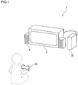
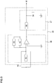
- FIG. 1 shows the usage environment of a game system according to the embodiment of the present invention.
- a game system 1 is provided with an image display device 3, an audio output device 4, a game device 10, and a controller 20.
- the image display device 3, the audio output device 4, and the controller 20 are connected to the game device 10.
- the image display device 3 is a display to process an image signal.
- the image display device 3 displays a game screen upon the reception of the image signal generated in the game device 10.
- the audio output device 4 is a speaker to output audio.
- the audio output device 4 outputs game audio upon the reception of the audio signal generated in the game device 10.
- the image display device 3 and the audio output device 4 constitute an output device in the game system 1.
- the game device 10 and the output device may be connected via wires such as an AV cable or may be connected wirelessly.
- a home network built with, for example, a network (LAN) cable or a wireless LAN, may be established between the game device 10 and the output device.
- LAN network
- the controller 20 is an input device for a user to input game operation data to move a character in the game
- the game device 10 is a processing device which processes a game application based on the game operation data provided by the controller 20 and creates the image signal and audio signal indicating the processing result of the game application.
- the technique shown in the embodiment can be realized not only in game applications but in an entertainment system provided with a processing device to execute other kinds of applications.
- the game system 1 in which a game application is executed will be explained as follows as a representation of entertainment systems.
- the controller 20 has a function of transmitting the game operation data input by the user to the game device 10, and in the embodiment, the controller 20 is provided as a wireless controller which communicates wirelessly with the game device 10.
- the controller 20 and the game device 10 may establish a wireless connection by using Bluetooth (registered trademark) protocol.
- the game device 10 functions as a base unit, in other words, a master
- the controller 20 functions as a slave unit, in other words, a slave.
- the controller 20 is not limited to a wireless controller and may be a wired controller which is connected to the game device 10 via a cable.
- the controller 20 is activated by a battery which is not shown, and is provided with a plurality of buttons and keys for user manipulation to progress the game.
- the manipulation data is periodically transmitted to the game device 10 as the game operation data wirelessly.
- the controller 20 is provided with a three axis acceleration sensor which detects acceleration in three axes, and an angular velocity sensor which detects angular velocity around a predetermined axis.
- the three axis acceleration sensor and the angular velocity sensor constitute the motion sensor which detects the movement of the controller 20.
- detection value of each sensor is treated as the game operation data and transmitted periodically to the game device 10 wirelessly. For example, by moving the controller 20 as if it were a steering wheel of a car, the output data of the three axis acceleration sensor and the angular velocity sensor are used as game operation data in a racing game where cars are moved in the game.
- the game device 10 receives the game operation data on the game application from the controller 20, controls the game progress in accordance with the game operation data, and generates the game image signal and the game audio signal.
- the generated game image signal and the game audio signal are output by the image display device 3 and the audio output device 4, respectively.
- the game device 10 has a function of transmitting to the controller 20 the vibration control signal to vibrate the controller 20 in accordance with the progress status of the game application.
- the controller 20 has the vibrator, and upon the reception of a vibration starting signal, the controller 20 starts driving the vibrator; and upon the reception of a vibration terminating signal, the controller 20 terminates driving the vibrator.
- the game device 10 may transmit for every transmission frame a vibration controlling signal indicating whether to drive the vibrator; and in that case, the vibration of the controller 20 is controlled in accordance with the vibration controlling signal.
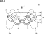
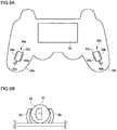
- Fig. 2 shows the exterior configuration of a controller.
- the controller 20 is provided with a direction key 21, an analog stick 27, and four different manipulation buttons 26.
- the four different buttons 22-25 are marked with different figures in different colors so as to distinguish one button from another. More specifically, a ⁇ button 22 is marked with a red circle, a ⁇ button 23 with a blue cross, a ⁇ button 24 with a purple square, and a ⁇ button 25 with a green triangle.
- the user grips a left grip part 28a with his or her left hand, a right grip part 28b with his or her right hand, and manipulates the controller 20.
- the direction key 21, the analog stick 27, and the manipulation buttons 26 are provided on a top housing 30 so that the user can manipulate them while gripping the left grip part 28a and the right grip part 28b.
- the vibrators provided with, for example, motors, are placed inside of the housings of the left grip part 28a and the right grip part 28b.
- a wireless communication module of the controller 20 receives the vibration starting signal from the game device 10, the right and left vibrators are driven.
- the vibrating motion is then transmitted the housing of the controller 20, and the controller 20 vibrates.
- a substrate for controlling the function of the controller 20 is placed near the center of the interior of the housing of the controller 20.
- the previously mentioned three axis acceleration sensor and the angular velocity sensor are installed on the substrate.
- the housing which constitutes the outer frame of the controller 20 is constituted by fitting a bottom housing and a top housing to each other, and a vibrator and a substrate are fixed to the bottom housing.
- the three axis acceleration sensor and the angular velocity sensor on the substrate detect the movement of the controller 20, and when the vibrator is driven, the vibration component of the controller 20 generated by driving the vibrator is included in the detection value. If the above mentioned racing game has a game setting in which a car runs straight by maintaining the controller 20 in a horizontal position, it is conceivable that the car which should run straight runs in zigzags due to the vibration component when the vibrator is driven. Since such behavior of the car gives the user unpleasant feeling, the vibration component from the vibrator is preferably removed to a maximum extent from the game operation data.
- the mechanism of reflecting the position and the movement of the controller 20 affected by the movement of the user in a character in the game the user is playing will be explained as precisely as possible as follows.
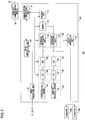
- Fig. 3 shows the internal configuration of a controller.
- the controller 20 has a processing unit 90 and is further provided with vibrators 80a and 80b which are provided with motors and eccentric members, and a wireless communication module 92.
- the vibrators 80a and 80b are placed in the left grip part 28a and right grip part 28b, respectively in the inside of housing of the controller 20.
- the wireless communication module 92 has a function of transmitting and receiving data to and from the wireless communication module of the game device 10.
- the processing unit 90 performs the desired process in the controller 20.
- the functions of the processing unit 90 and the wireless communication module 92 may be realized as a circuit built in a substrate provided inside of the housing.
- the processing unit 90 is provided with a main controlling unit 50, an input reception unit 52, a sensor block 56, a filter block 60, an analog-to-digital conversion device 64, an averaging processing block 68, a memory 70, a readout unit 72, a communication controlling unit 74, and a drive controlling unit 76.
- the communication controlling unit 74 transmits and receives necessary data to and from the wireless communication module 92.
- the input reception unit 52 receives the manipulation data from an input unit, for example, the direction key 21, the manipulation button 26, and the analog stick 27, and transmits the manipulation data to the main controlling unit 50.
- the main controlling unit 50 provides the received manipulation data to the memory 70 and stores the manipulation data in the memory 70.
- the manipulation data from various input units are overwritten in the respective area assigned for each manipulation data as game operation data in the memory 70.
- the communication controlling unit 74 controls the transmission process of the wireless communication module 92 at predetermined cycles. Since the frame cycle of a game image of the game device 10 is set at 1/60 s, the transmission cycle of the wireless communication module 92 is set at less than 1/60 s, for example, 11.25 ms.
- the readout unit 72 reads out game operation data from the memory 70 in accordance with the transmission cycle of the wireless communication module 92, and provides the game operation data to the communication controlling unit 74. Since the manipulation data from the various input units are overwritten and saved in the respective storage areas, the readout unit 72 can provide the manipulation data as the latest game operation data to the communication controlling unit 74.
- the sensor block 56 has a plurality of acceleration sensors 54 and angular velocity sensors 53.
- the sensor block 56 includes three axis acceleration sensor, the sensor block 56 is provided with three acceleration sensors 54.
- the acceleration sensor 54 and the angular velocity sensor 53 detect the movement of the controller 20 caused by the movement of the user.
- the detection values, which are output data, of the acceleration sensor 54 and the angular velocity sensor 53 are used as the game operation data of a game application in the embodiment.
- the filter block 60 has a plurality of low pass filters (LPF) 58 and 57.
- LPF 58 is installed at the downstream of acceleration sensor 54, and is a filter which passes the frequency component below the cutoff frequency of the output data of acceleration sensor 54, and attenuates a frequency component close to or above the cutoff frequency.
- the LPF 57 is installed at the downstream of the angular velocity sensor 53, and is a filter which passes the frequency component below the cutoff frequency of the output data of the angular velocity sensor 53, and attenuates a frequency component close to or above the cutoff frequency.
- LPF 58 and LPF 57 may be constituted as passive filters and to have the same cutoff frequencies. Compared with an active filter, the passive filter does not require electricity for the filter operation; and thus, the passive filter is suitable for use in the battery driven controller 20.
- an additional passive filter may be installed between the acceleration sensor 54 and LPF 58.
- the passive filter may be formed inside of the acceleration sensor 54, or may be formed by the internal resistor of the acceleration sensor 54 and the condenser installed outside of the acceleration sensor 54. Also, the passive filter may be formed outside of the acceleration sensor 54 so as to become in series with LPF 58.
- the cutoff frequency of the passive filter is set higher than the cutoff frequency of LPF 58.
- an additional active filter may be installed between the angular velocity sensor 53 and LPF 57.
- the active filter has an amplifying component, for example, an OP amp and a transistor, and has a function of amplifying the output data of the angular velocity sensor 53 and providing the amplified output data to LPF 57. Since the output data of the angular velocity sensor 53 is smaller when compared with the output data of the acceleration sensor 54, by amplifying with the active filter, the output data can be used preferably as the game operation data.
- the cutoff frequency of the active filter is set higher than the cutoff frequency of LPF 57.
- the analog-to-digital conversion device 64 is provided with a plurality of analog-to-digital converters (ADC) 62 and 63.
- ADC 62 converts an analog signal output from the LPF 58 into a digital signal.
- the ADC 63 converts an analog signal output from the LPF 57 into a digital signal.
- a sampling cycle is set smaller than the transmission cycle of the wireless communication module 92.
- the sampling cycle may be, for example, about 2 ms.
- the analog-to-digital conversion device 64 may retain a fixed sampling cycle or allow the sampling cycle to be controlled as desired by the main controlling unit 50.
- the averaging processing block 68 is provided with a plurality of averaging processing units 66 and 67.
- the averaging processing unit 66 performs the averaging process on sampling values output from ADC 62 during the transmission cycle of the wireless communication module 92, and overwrites the averaged value as game operation data in the area assigned in the memory 70.
- the averaging processing unit 67 performs the averaging process on sampling values output from the ADC 63 during the transmission cycle of the wireless communication module 92, and overwrites the averaged value as game operation data in the area assigned in the memory 70.
- the averaging processing units 66 and 67 can reduce the influence of the vibration component of the housing attributed to the vibrator 80 superimposed on the sensor output data by averaging the sampling values during the transmission cycle.
- the averaging processing units 66 and 67 do not need to exist in the processing unit 90, and in that case, the sampling values of ADCs 62 and 63 are overwritten and stored as game operation data in the respective areas in the memory 70 at a sampling cycle.
- the readout unit 72 reads out the game operation data from the memory 70 in accordance with the transmission time specified by the transmission cycle of the wireless communication module 92, and provides the game operation data to the communication controlling unit 74. Since the sensor output data provided by the averaging processing units 66 and 67 and the ADCs 62 and 63 are overwritten and saved in the respective storage areas, the readout unit 72 can provide the latest sensor output data, which is included in the game operation data, to the communication controlling unit 74.
- the communication controlling unit 74 transmits, via the wireless communication module 92 and to the game device 10, the sensor output data as the game operation data which is acquired by the motion sensor, more specifically, the acceleration sensor 54 and the angular velocity sensor 53, along with the manipulation data of, for example, the manipulation button 26 which is received by the input reception unit 52.
- the wireless communication module 92 Upon the reception of a vibration controlling signal indicating the start or termination of the vibration from the game device 10, the wireless communication module 92 provides the vibration controlling signal to the main controlling unit 50.
- the main controlling unit 50 provides the vibration controlling signal to the drive controlling unit 76, and the drive controlling unit 76 controls the drive of the vibrators 80a and 80b based on the vibration controlling signal.
- the drive controlling unit 76 may be provided as a switch for driving the vibrators 80a and 80b, or as a PWM controlling unit for varying a duty ratio of a supply voltage.
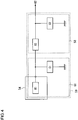
- Fig. 4 shows the configuration of a low pass filter installed at the output of the acceleration sensor.
- the output data of the acceleration sensor 54 passes through a two-stage structured second-order passive filter 59 provided with LPF 61 and LPF 58 and is filter processed by the second-order passive filter 59.
- the second-order passive filter 59 constitutes a two-stage low pass filter.
- the cutoff frequency of the second-order passive filter 59 is set as the smaller of the cutoff frequency of LPF 61 and the cutoff frequency of LPF 58.
- LPF 58 is positioned at the downstream of the output of the acceleration sensor 54
- LPF 61 is positioned between the acceleration sensor 54 and LPF 58.
- LPF 61 is provided with an internal resistor R1 in the acceleration sensor 54 and a capacitor C1.
- LPF 58 is provided with a resistor R2 and a capacitor C2.
- the order of the filter is not limited to the second order, the second order is preferred in the controller 20 as will herein after be described in detail.
- the controller 20 in the embodiment has the vibrator 80 which vibrates, along with the acceleration sensor 54 and the angular velocity sensor 53.
- the motion sensor such as the acceleration sensor 54
- the vibration component of the controller 20 attributed to the vibrating motion of the vibrator 80 can be removed from the output data of the acceleration sensor 54, while the acceleration sensor 54 can detect the movement of the controller 20 caused by the movement of the user.
- the resonance element attributed to the vibrating motion of the vibrator 80 is far larger than the vibration component of the vibrator 80.
- the peak value of the natural frequency of the controller 20 is set high by tightly fixing the member in the housing to the housing.
- the cutoff frequency of LPF 58 can be set lower than the peak value of the natural frequency of the controller 20, at least a part of the resonance element can be removed in the second-order passive filter 59. In this case, by setting the cutoff frequency of LPF 58 to two thirds or less of the peak value of the natural frequency of the controller 20, the majority of resonance elements can be removed.
- Fig. 5 shows the configuration of a low pass filter installed at the output of the angular velocity sensor.
- the output data of the angular velocity sensor 53 passes through a two-stage structured second-order low pass filter 44 provided with LPF 42 and LPF 57 and is filter processed by the second-order low pass filter 44.
- the cutoff frequency of the second-order low pass filter 44 is set as the smaller of the cutoff frequency of LPF 42 and the cutoff frequency of LPF 57.
- LPF 57 is positioned at the downstream of the output of the angular velocity sensor 53
- LPF 42 is positioned between the angular velocity sensor 53 and LPF 57.
- LPF 42 is constituted as an active filter in order to amplify the output data of the angular velocity sensor 53.
- LPF 42 is provided with an internal resistor R3 in the angular velocity sensor 53, an OP amp, a resistor R4, and a capacitor C3.
- LPF 57 is provided with a resistor R5 and a capacitor C4.
- the angular velocity sensor 53 can detect the movement of the controller 20 caused by the movement of the user, and the vibration component of the controller 20 attributed to the vibrating motion of the vibrator 80 can be removed from the output data of the angular velocity sensor 53.
- the cutoff frequency of LPF 57 can be set lower than the peak value of the natural frequency of the controller 20, and at least a part of the resonance element can be removed in the two-stage low pass filter 44. In this case, by setting the cutoff frequency of LPF 57 to two thirds or less of the peak value of the natural frequency of the controller 20, the majority of resonance elements can be removed.
- FIG. 6A shows the substrate and the vibrator which are fixed in the bottom housing being exposed after the removal of the top housing of the controller.
- a substrate 88 has a horizontally oriented shape, and is fixed to a front central position of the bottom housing.
- the vibrator 80a is provided with a motor 82a and an eccentric member 86a attached at the end of the motor shaft, and is fixed to a position in the left grip part 28a of the bottom housing while being sandwiched by a pair of binding lugs 84a.
- the vibrator 80b is provided with a motor 82b and an eccentric member 86b, and is fixed to a position in the right grip part 28b of the bottom housing while being sandwiched by a pair of binding lugs 84b.
- the eccentric member 86 has a semicircular shape and is eccentrically fixed to the motor shaft, and when the motor shaft rotates, the eccentric member 86 vibrates the housing.
- Fig. 6B shows the fixed structure of a motor.
- a pair of binding lugs extends from the bottom housing, and the motor 82 is pushed between the pair of binding lugs 84. While the motor 82 is pushed in, the pair of binding lugs 84 has elasticity for pushing the motor 82 in the direction in which the pair of binding lugs becomes closer to each other, and the motor 82 is tightly fixed to the bottom housing by the elastic force.
- the substrate 88 is also tightly fixed to the bottom housing in order to raise the natural frequency.
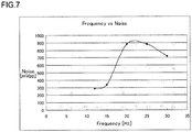
- Fig. 7 shows the result of the experiment in which the relation is acquired of the vibration frequency of the controller and the noise level detected by the acceleration sensor.
- the output data of the acceleration sensor 54 is a detected value without filtering with the filters, such as LPF 61 or LPF 58, in other words, the detected value for the acceleration sensor 54 is shown.
- the tendency is found in which the noise detected by the acceleration sensor 54 increases considerably when the vibrating frequency applied to the controller 20 is between 15Hz and 20Hz.
- the peak value of the natural frequency (natural vibration frequency) of the controller 20 is approximately 22Hz. Accordingly, the inventor found from the experimental result that in order to effectively remove the vibration component applied to the housing of the controller 20, it is preferable the cutoff frequency of LPF 58 is set to 15Hz or less.
- the frequency of vibration given to the controller 20 by the movement of the user is lower than the frequency given to the controller 20 by the vibrator 80.
- the frequency of vibration given to the controller 20 does not usually exceed 15Hz. Therefore, if the cutoff frequency of LPF 58 is set to a predetermined value of 15Hz or less, for example to 15Hz, LPF 58 can suitably output the vibration component attributed to the movement of the user and the vibration component attributed to the vibrating motion of the vibrator 80 can be removed effectively.
- the cutoff frequency of LPF 58 is lowered to a maximum extent within the range where the movement of the controller 20 caused by the movement of the user can be detected (e.g., about 5Hz)
- the vibrating motion attributed to the vibrator 80 can be effectively removed;
- the lag time in LPF 58 becomes longer due to the effect of a time constant.
- the game operation data of the user is preferably reflected in the movement of the character in the game the user is playing instantaneously, and the lag time in LPF 58 is preferably reduced to a maximum extent. More specifically, the lag time is preferably set shorter than the transmission cycle of the wireless communication module 92. In this case, by installing LPF 58, the lag longer than two transmission cycles is not generated in the transmission of the sensor output data, and the maximum lag is one transmission cycle.
- the resistance of the resistor R2 is set to 33k ⁇ , and the capacitance of the capacitor C2 is set to 0.33 ⁇ F.
- the cutoff frequency of a CR filter becomes about 15Hz.
- the lag time due to the time constant is about 10.89ms.
- the lag time of the LPF 58 becomes shorter than the transmission cycle of the wireless communication module 92.
- the maximum transmission lag time for the sensor output data can be kept to one transmission cycle of the wireless communication module 92.
- LPF 61 placed in the former stage of LPF 58 may have the same structure as the structure of LPF 58 so as to have the cutoff frequency of 15Hz.
- the maximum transmission lag time caused by the second-order passive filter 59 can be kept to two transmission cycles of the wireless communication module 92.
- the lag time which is acceptable in the game in which the real time performance is required can be realized.
- LPF 57 may have the same structure as the structure of LPF 58 which has the cutoff frequency of 15Hz. More specifically, the resistance of the resistor R5 can be set to 33k ⁇ , and the capacitance of the capacitor C4 can be set to 0.33 ⁇ F. Also, as for LPF 42 placed in the former stage of LPF 57, the resistance and the capacitance may be set to have the cutoff frequency of about 1kHz. In this case, the maximum lag time caused by the second-order low pass filter 44 can be kept to two transmission cycles of the wireless communication module 92. Thus, the lag time which is acceptable in the game in which the real time performance is required can be realized.
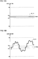
- Figs. 8A and 8B show the simulation result for LPF placed at the downstream of the acceleration sensor.
- the voltage level in the movable frequency band and the frequency characteristics in the noise frequency band are examined in the situations where the one or two LPFs are placed at the downstream of the acceleration sensor 54 as follows:
- Fig. 8B shows the frequency characteristics in the noise frequency band.
- the simulation result revealed that the noise component cannot be suitably removed in the situation where one LPF having 15Hz cutoff frequency is installed.
- the range from 10Hz to 35Hz is shown as the noise frequency band, the frequency of 15Hz or higher is considered as the noise component in the environment in the embodiment.
- the second-order passive filter 59 provided with two LPFs, LPF 61 and LPF 58, at the downstream of the acceleration sensor 54, the second-order passive filter 59 can output the movement of the user suitably, and the vibration component attributed to the vibrating motion of the vibrator 80 can be suitably removed from the sensor output data.
- LPF 61 and LPF 58 having the cutoff frequency of 15Hz are installed in two stages at the downstream of the acceleration sensor 54 in the embodiment.
- Fig. 9 shows a variation example of LPF.
- the LPF 58 is provided so that filter circuits 58a or 58b which have different cutoff frequencies can be used selectively by a switch 55.
- LPF 61 shown in Fig. 4 is installed between the acceleration sensor 54 and LPF 58, the schematic illustration is omitted.
- the filter circuit 58a may, for example, have a cutoff frequency of 10Hz, and the filter circuit 58b may have a cutoff frequency of 15Hz.
- a bypassing route 58c which bypasses filter circuits can also be selected with the switch 55.
- the sensor output is preferably unconnected to the filter circuit from the lag time perspective in the game application where the immediate reflection of the game operation data of the user in the movement of the character in the game is required.
- the main controlling unit 50 controls the switch 55 so as to connect the acceleration sensor 54 and the bypassing route 58c.
- the main controlling unit 50 determines the destination for the acceleration sensor 54 according to whether the game application requires low latency.
- the main controlling unit 50 controls the switch 55 so as to connect the acceleration sensor 54 and the filter circuit 58b; and in the game application where low latency is not required, the main controlling unit 50 controls the switch 55 so as to connect the acceleration sensor 54 and the filter circuit 58a.
- the switch 55 controls the switch 55 so as to connect the acceleration sensor 54 and the filter circuit 58a.
- the information indicating whether the vibrating motion is generated and whether the low latency is required in the game application may be sent beforehand to the controller 20 from the game device 10.
- the game device 10 may read the information out and notify the controller 20 of the information beforehand.
- the main controlling unit 50 sets the connection destination of the switch 55 based on the notified information.
- the driving of the vibrator 80 is controlled by the vibration controlling signal sent form the game device 10. Therefore, upon the reception of the vibration starting signal, the main controlling unit 50 may switch the switch 55 from the bypassing route 58c to the filter circuit 58a or filter circuit 58b, and upon the reception of the vibration terminating signal, the main controlling unit 50 may return the switch 55 back to the bypassing route 58c.
- the vibration component attributed to the vibrating motion of the vibrator 80 is filter processed while the vibrating motion of the vibrator 80 is generated, and the output of the acceleration sensor 54 is connected to the bypassing route 58c while the vibrating motion of the vibrator 80 is not generated, the lag due to the filter processing can be avoided. Described above is the explanation on the LPF 58 installed at the downstream of the acceleration sensor 54.
- LPF 57 installed at the downstream of the angular velocity sensor 53 may have the same configuration.
- Fig. 10 shows the configuration of a game device.
- the game device 10 is provided with a wireless communication module 100, a communication controlling unit 102, a main controlling unit 104, a sensor output correction unit 110, a vibration controlling signal creation unit 120, an application processor 130, and an output unit 140.
- the processing functions according to the embodiment are implemented by any CPU, a memory or a program loaded into the memory. Configurations are implemented by the cooperation of hardware components.
- the program may be built in the game device 10 or may be provided from outside, being stored in the recording medium.
- the CPU of the game device 10 accomplishes the functions as the communication controlling unit 102, the main controlling unit 104, the sensor output correction unit 110, the vibration controlling signal creation unit 120, and the application processor 130.
- the game device 10 may have a plurality of CPU's, considering the configuration of the hardware.
- a CPU may function as the communication controlling unit 102 which controls the function of the wireless communication module 100
- another CPU may function as the main controlling unit 104 which controls the function of the whole game device 10
- another CPU may function as the application processor 130 and the vibration controlling signal creation unit 120
- another CPU may function as the sensor output correction unit 110.
- the communication controlling unit 102 transmits and receives the required data to and from the wireless communication module 100, controls the communication process of the wireless communication module 100, and the wireless communication module 100 establishes the wireless communication with the wireless communication module 92 of the controller 20.
- the wireless communication module 100 and the wireless communication module 92 establish connections by, for example, a Bluetooth (registered trademark) protocol.
- the data such as the game operation data is sent at predetermined cycles from the wireless communication module 92 of the controller 20, and the communication controlling unit 102 provides the data received by the wireless communication module 100 to the main controlling unit 104.
- the main controlling unit 104 provides the game operation data input through the input unit such as the direction key 21 to the application processor 130.
- the application processor 130 reflects the game operation data in the process of the game application.
- the main controlling unit 104 provides the digitalized sensor output data to the sensor output correction unit 110.
- the game application started at the application processor 130 uses the sensor output data as game operation data, and the sensor output correction unit 110 corrects the sensor output data appropriately and provides the corrected sensor output data to the application processor 130 as game operation data.
- the application processor 130 reflects the sensor output data in the process of the game application.
- a sensor output acquisition unit 112 Upon the reception of the sensor output data, a sensor output acquisition unit 112 provides the sensor output data to a masking processing unit 118.
- the sensor output acquisition unit 112 may perform the averaging process on the sensor output data provided from the controller 20 at predetermined cycles and then provide the averaged sensor output data to the masking processing unit 118. For example, the sensor output acquisition unit 112 performs the averaging process on the sensor output data of the predetermined number of cycles. As described above, the sensor output acquisition unit 112 can reduce the influence of the vibration component of the housing attributed to the vibrator 80 superimposed on the sensor output data by averaging the predetermined number of sensor output data provided in succession.
- the masking processing unit 118 performs the masking process on the acceleration sensor output data within the predetermined range of masking including zero acceleration.
- the masking processing unit 118 corrects such acceleration sensor output data to have zero acceleration.
- the masking processing unit 118 also performs the masking process on the angular velocity sensor output data within the predetermined range of masking including zero angular velocity. More specifically, the masking processing unit 118 corrects such angular velocity sensor output data to have zero angular velocity.
- Figs. 11A and 11B show the sensor output data of the detected motion of a controller caused by the movement of a user.
- the sensor output data is the acceleration sensor output data of a z-axis element (vertical element).
- Fig. 11A shows a sensor output data SO_10 where the user grips the controller in a horizontal position without any vertical movements
- Fig. 11B shows a sensor output data SO_20 where the user grips the controller in a horizontal position and moves the controller up and down in a vertical direction.
- Figs. 12A and 12B show sensor output data of the detected vibrating motion of a controller, caused by the vibrating motion of a vibrator, along with the movement of a controller, caused by the movement of a user.
- Fig. 12A shows a sensor output data SO_12 where the user grips the controller in a horizontal position without any vertical movements
- Fig. 12B shows a sensor output data SO_22 where the user grips the controller in a horizontal position and moves the controller up and down in a vertical direction.
- Figs. 12A and 12B show the vibrating motions of the controller 20 attributed to the vibrating motions of the vibrator 80 are superimposed on the movements of the controller 20 caused by the movements of the user.
- the vibration component of the vibrator 80 When the vibration component of the vibrator 80 is superimposed on the sensor output data and the sensor output data is used as the game operation data to move the game character, the behavior of the game character shown is unintended to the user with respect to the game input by the movement of the user. Thus, all the noise components attributed to the vibrating motion of the vibrator 80 are preferably removed in a normal situation.
- the inventor has acquired a knowledge through the experiment using test subjects that there is a difference in the influence given to the user by the noise component attributed to the vibration motion of the vibrator 80 between when the user moves the controller 20 and when the user does not move the controller 20.
- the user has a tendency to have unpleasant feeling when the game character moves due to the noise component attributed to the vibrating motion of the vibrator 80 against the user's intension of making the game character to be stationary by not moving the controller 20, on the other hand, the user barely notices the effect on the game character caused by the noise component attributed to the vibrating motion of the vibrator 80 when the user moves the controller 20 with intension of moving the game character.
- the inventor came to the finding that since it was not easy to move the controller 20 accurately as desired, the noise component of an amplitude smaller than the movement of the user can be considered to be in the error range of the movement of the user.
- the sensor output data of SO_12 shown in Fig. 12A is undesirable because the game character moves against the intention of the user wanting to fix the movement of the game character, and on the other hand, it can be seen that the sensor output data of SO_22 shown in Fig. 12B can achieve the movement of the game character without giving any unpleasant feelings to the user.
- the masking processing unit 118 in the embodiment corrects the sensor output data by performing the masking process on the amplitude component within the predetermined range including zero acceleration based on the above mentioned finding.
- Figs. 13A and 13B show the range of acceleration of masking.
- Fig. 13A shows the relation between sensor output data SO_12 and the range of masking
- Fig. 13B shows the relation between sensor output data SO_22 and the range of masking.
- the range of masking is set to -Ath or larger (Ath is a positive predetermined value) and to Ath or smaller, and an absolute value of a negative lower limit and a positive upper limit within the range of masking are equal. This is caused due to the noise component attributed to the vibrator 80 swings to almost evenly in the positive and negative based on the current posture of the controller 20. An absolute value of a negative lower limit and a positive upper limit within the range of masking do not need to be always equal.
- Fig. 14 shows the relation of a sensor output data and acceleration during masking process.
- the sensor output data takes the value of FFh from 00h (hex)
- the sensor output data 00h corresponds to the acceleration of -3G
- the sensor output data FFh corresponds to the acceleration of +3G.
- the masking processing unit 118 corrects the acceleration to zero and outputs the zero acceleration when the sensor output data is in the range from 74h to 8Ch.
- Figs. 15A and 15B show the result of masking processing the sensor output data shown in Figs. 13A and 13B .
- Fig. 15A shows a sensor output data SO_14 generated by masking processing the sensor output data SO_12
- Fig. 15B shows a sensor output data SO_24 generated by masking processing the sensor output data SO_22.
- the sensor output data SO_14 in Fig. 15A appropriately expresses the state of the controller 20 which is held stationary by the user by removing the acceleration element in the range of masking.
- the sensor output data SO_24 in Fig. 15B substantially expresses the movement of the controller 20 caused by the movement of the user even though the acceleration element in the range of masking is removed.
- the masking processing unit 118 can correct the sensor output data to the appropriate game operation data by performing the masking process on the predetermined acceleration element around zero acceleration and disregarding the acceleration element.
- the masking processing unit 118 provides the corrected sensor output data to the application processor 130 as the game operation data.
- the application processor 130 creates the image signal and the audio signal which reflect the game operation data provided by the masking processing unit 118 in the movement of the game character along with the game operation data through, for example, the manipulation button 26, directly provided from the main controlling unit 104, and provides the image signal and the audio signal respectively to the image display device 3 and the audio output device 4 from the output unit 140.
- the masking processing unit 118 may determine whether to perform the masking process based on the movement state of the controller 20. As described above, since the masking process is a process to set the acceleration element within the range of masking to be zero, when the user moves the controller 20, the motion element is masked and discarded.
- the movement state determination unit 114 determines the movement state of the controller 20 and based on the result of the determination, the execution of the masking process may be controlled. More specifically, the movement state determination unit 114 acquires the sensor output data from the sensor output acquisition unit 112 and determines whether the sensor output data continues taking the value within the range of masking in succession for a predetermined period of time. The determination time may be, for example, a few seconds. When the movement state determination unit 114 determines that the sensor output data continues taking the value within the range of masking for the predetermined period of time, the movement state determination unit 114 notifies the masking processing unit 118 of the determination result. Upon the reception of the determination result, the masking processing unit 118 starts performing the masking process on the sensor output data.
- the movement state determination unit 114 determines that the sensor output data takes the value outside the range of masking
- the movement state determination unit 114 notifies the masking processing unit 118 of the determination result.
- the masking processing unit 118 terminates performing the masking process on the sensor output data. As described above, having the movement state determination unit 114 monitor the movement state of the controller 20, the masking processing unit 118 can perform the masking process at an appropriate time.
- the movement state of the controller 20 may be determined by whether the vibrator 80 is vibrating.
- a vibration controlling signal creation unit 120 creates the vibration controlling signal by the instruction from the application processor 130 and provides the vibration controlling signal to the main controlling unit 104.
- the communication controlling unit 102 Upon the reception of the vibration controlling signal, the communication controlling unit 102 transmits the vibration controlling signal to the controller 20 from the wireless communication module 100.
- the vibrator 80 of the controller 20 is controlled by the vibration controlling signal created by the vibration controlling signal creation unit 120, the approach to determine the movement state of the controller 20 is also effective by using the control.
- a vibration state determination unit 116 receives the vibration controlling signal from the vibration controlling signal creation unit 120. As a result, the vibration state determination unit 116 determines whether the vibrator 80 will start or terminate the vibration. Upon the reception of the vibration starting signal, the vibration state determination unit 116 determines that the vibrator 80 is in the state to vibrate and notifies the masking processing unit 118 of the determination result. Upon the reception of the notification, the masking processing unit 118 starts performing the masking process on the sensor output data. Upon the reception of the vibration terminating signal, the vibration state determination unit 116 determines that the vibrator 80 is in the state to terminate the vibration and notifies the masking processing unit 118 of the determination result.
- the masking processing unit 118 Upon the reception of the notification, the masking processing unit 118 terminates the masking process on the sensor output data. It takes a certain amount of time until the inertia rotation of the eccentric member 86 stops after the vibration terminating signal is provided to the controller 20 followed by the termination of the voltage application to the motor 82. Therefore, taking the time required for the rotation of the eccentric member 86 to stop after the termination of the voltage application into consideration, the masking processing unit 118 may stop the masking process after the predetermined period after the reception of the notification. As described above, having the vibration state determination unit 116 determines whether the controller 20 is in the state to vibrate sympathetically with the vibrating motion of the vibrator 80, the masking processing unit 118 can perform the masking process at an appropriate time.
- the controlling can be done using the movement state determination unit 114 or the vibration state determination unit 116 alone. However, by combining the movement state determination unit 114 and the vibration state determination unit 116, the masking process in which the movement state of the controller 20 is reflected can be achieved.
- the masking process control based on the determination result of the vibration state by the vibration state determination unit 116 may be given priority over the masking process control based on the determination result of the movement state by the movement state determination unit 114. Since the vibrating motion of the controller 20 attributed to the vibrating motion of the vibrator 80 is not generated if the vibrator 80 is not vibrating, better control of the masking process can be achieved by determining whether the vibrator 80 is vibrating.
- the game device 10 has the function of correcting the sensor output data.
- the function of correcting the sensor output data may be realized by the controller 20.
- the controller 20 can have the function of correcting the sensor output data.
- the functions of the movement state determination unit 114 and the vibration state determination unit 116 can be realized by the main controlling unit 50.
Landscapes
- Engineering & Computer Science (AREA)
- Multimedia (AREA)
- Human Computer Interaction (AREA)
- Computer Networks & Wireless Communication (AREA)
- User Interface Of Digital Computer (AREA)
Claims (9)
- Spielsteuerung (20), die betriebsbereit ist, Spielbetriebsdaten zu einer Spielvorrichtung (10) zu übertragen, aufweisend:ein Gehäuse;einen Bewegungssensor (56), der betriebsbereit ist, die Bewegung der Spielsteuerung zu erfassen;ein Tiefpassfilter (57), das am Ausgang des Bewegungssensors installiert ist; undmindestens einen Vibrator (80), wobeider Bewegungssensor, das Tiefpassfilter und der mindestens eine Vibrator im Inneren des Gehäuses angeordnet sind, wobei der mindestens eine Vibrator am Gehäuse befestigt ist; unddie Grenzfrequenz des Tiefpassfilters niedriger als die natürliche Frequenz der Spielsteuerung eingestellt ist, wobei die Grenzfrequenz des Tiefpassfilters so eingestellt ist, dass mindestens ein Teil der Vibrationskomponente des Gehäuses, die auf die Vibrationsbewegung des Vibrators zurückzuführen ist, entfernt werden kann.
- Spielsteuerung nach Anspruch 1, wobei die Grenzfrequenz des Tiefpassfilters auf zwei Drittel oder weniger des Spitzenwertes der natürlichen Frequenz der Spielsteuerung eingestellt ist.
- Spielsteuerung nach Anspruch 1, wobei das Tiefpassfilter so gestaltet ist, dass Filterschaltungen mit unterschiedlichen Grenzfrequenzen selektiv verwendet werden können.
- Spielsteuerung nach Anspruch 1, wobei die Grenzfrequenz des Tiefpassfilters auf einen vorgegebenen Wert von 15Hz oder weniger eingestellt ist.
- Spielsteuerung nach einem vorangehenden Anspruch, ferner aufweisend:ein drahtloses Kommunikationsmodul (92), das betriebsbereit ist, die Ausgangsdaten des Bewegungssensors in einem vorgegebenen Zyklus zu übertragen, wobeidie Verzögerungszeit, die durch das Tiefpassfilter verursacht wird, kürzer als die zweifache Dauer eines Übertragungszyklus des drahtlosen Kommunikationsmoduls eingestellt ist.
- Spielsteuerung nach Anspruch 5, wobei die Verzögerungszeit, die durch das Tiefpassfilter verursacht wird, kürzer als die Dauer eines Übertragungszyklus des drahtlosen Kommunikationsmoduls eingestellt ist.
- Spielsteuerung nach einem vorangehenden Anspruch, ferner aufweisend:ein drahtloses Kommunikationsmodul, das betriebsbereit ist, die Ausgangsdaten des Bewegungssensors in einem vorgegebenen Zyklus zu übertragen;ein weiteres Tiefpassfilter, das zwischen dem Bewegungssensor und dem Tiefpassfilter installiert ist, wobeidie Verzögerungszeit, die durch die Tiefpassfilter in zwei Stufen verursacht wird, kürzer als die zweifache Dauer eines Übertragungszyklus des drahtlosen Kommunikationsmoduls eingestellt ist.
- Spielsteuerung nach Anspruch 7, wobei die Verzögerungszeit, die durch jedes der Tiefpassfilter verursacht wird, die ein Zweistufen-Tiefpassfilter bilden, kürzer als die Dauer eines Übertragungszyklus des drahtlosen Kommunikationsmoduls eingestellt ist.
- Spielsteuerung nach einem vorangehenden Anspruch, wobei
der Bewegungssensor mindestens einen Beschleunigungssensor (54) und einen Winkelgeschwindigkeitssensor (53) enthält, ferner aufweisend:ein passives Filter, das zwischen dem Beschleunigungssensor und dem Tiefpassfilter installiert ist; undein aktives Filter, das zwischen dem Winkelgeschwindigkeitssensor und dem Tiefpassfilter installiert ist.
Applications Claiming Priority (2)
| Application Number | Priority Date | Filing Date | Title |
|---|---|---|---|
| JP2007180395 | 2007-07-09 | ||
| JP2007243065A JP4892443B2 (ja) | 2007-07-09 | 2007-09-19 | ゲームコントローラ |
Publications (3)
| Publication Number | Publication Date |
|---|---|
| EP2014341A1 EP2014341A1 (de) | 2009-01-14 |
| EP2014341B1 true EP2014341B1 (de) | 2017-06-21 |
| EP2014341B8 EP2014341B8 (de) | 2017-08-30 |
Family
ID=39884942
Family Applications (1)
| Application Number | Title | Priority Date | Filing Date |
|---|---|---|---|
| EP08252345.7A Active EP2014341B8 (de) | 2007-07-09 | 2008-07-09 | Spielsteuerung |
Country Status (2)
| Country | Link |
|---|---|
| US (1) | US9174122B2 (de) |
| EP (1) | EP2014341B8 (de) |
Cited By (1)
| Publication number | Priority date | Publication date | Assignee | Title |
|---|---|---|---|---|
| EP3345663B1 (de) * | 2017-01-10 | 2023-12-27 | Nintendo Co., Ltd. | Informationsverarbeitungsprogramm, informationsverarbeitungsvorrichtung, informationsverarbeitungssystem und informationsverarbeitungsverfahren |
Families Citing this family (28)
| Publication number | Priority date | Publication date | Assignee | Title |
|---|---|---|---|---|
| US8698898B2 (en) * | 2008-12-11 | 2014-04-15 | Lucasfilm Entertainment Company Ltd. | Controlling robotic motion of camera |
| JP5430246B2 (ja) * | 2009-06-23 | 2014-02-26 | 任天堂株式会社 | ゲーム装置およびゲームプログラム |
| US8964052B1 (en) | 2010-07-19 | 2015-02-24 | Lucasfilm Entertainment Company, Ltd. | Controlling a virtual camera |
| JP5642474B2 (ja) | 2010-09-24 | 2014-12-17 | ミネベア株式会社 | 入力装置、振動装置および入力検出方法 |
| US8456298B2 (en) | 2010-11-02 | 2013-06-04 | Timo Valtonen | Apparatus and method for portable tracking |
| US10073523B2 (en) | 2014-12-23 | 2018-09-11 | Immersion Corporation | Position control of a user input element associated with a haptic output device |
| JP2016136306A (ja) * | 2015-01-23 | 2016-07-28 | ソニー株式会社 | 情報処理装置、情報処理方法及びプログラム |
| JP6445921B2 (ja) * | 2015-04-21 | 2018-12-26 | 任天堂株式会社 | 振動信号生成プログラム、振動信号生成システム、振動信号生成装置、振動信号生成方法、およびデータ出力プログラム |
| EP3272402B1 (de) | 2016-06-10 | 2019-02-27 | Nintendo Co., Ltd. | Spielsteuergerät |
| JP6782567B2 (ja) | 2016-06-10 | 2020-11-11 | 任天堂株式会社 | ゲームコントローラ |
| JP6893763B2 (ja) | 2016-06-10 | 2021-06-23 | 任天堂株式会社 | ゲームコントローラ |
| JP6677580B2 (ja) | 2016-06-10 | 2020-04-08 | 任天堂株式会社 | ゲームコントローラ |
| JP7083226B2 (ja) | 2016-06-10 | 2022-06-10 | 任天堂株式会社 | ゲームコントローラ |
| EP3254739B1 (de) * | 2016-06-10 | 2020-03-25 | Nintendo Co., Ltd. | Spielsteuergerät |
| WO2018110434A1 (ja) | 2016-12-15 | 2018-06-21 | 株式会社ソニー・インタラクティブエンタテインメント | 振動デバイス、及び制御システム |
| WO2018110433A1 (ja) | 2016-12-15 | 2018-06-21 | 株式会社ソニー・インタラクティブエンタテインメント | 情報処理システム、振動制御方法、及びプログラム |
| JP6799077B2 (ja) | 2016-12-15 | 2020-12-09 | 株式会社ソニー・インタラクティブエンタテインメント | 情報処理システム、コントローラデバイス、コントローラデバイスの制御方法、及びプログラム |
| US12194375B2 (en) | 2017-01-25 | 2025-01-14 | Kieran S. Lyden | Game controller |
| US10507385B2 (en) | 2017-01-25 | 2019-12-17 | Kieran S. Lyden | Game controller |
| WO2018193514A1 (ja) | 2017-04-18 | 2018-10-25 | 株式会社ソニー・インタラクティブエンタテインメント | 振動制御装置 |
| JP6833018B2 (ja) | 2017-04-18 | 2021-02-24 | 株式会社ソニー・インタラクティブエンタテインメント | 振動制御装置 |
| JP6887011B2 (ja) | 2017-04-19 | 2021-06-16 | 株式会社ソニー・インタラクティブエンタテインメント | 振動制御装置 |
| WO2018198229A1 (ja) | 2017-04-26 | 2018-11-01 | 株式会社ソニー・インタラクティブエンタテインメント | 振動制御装置 |
| JP6771435B2 (ja) | 2017-07-20 | 2020-10-21 | 株式会社ソニー・インタラクティブエンタテインメント | 情報処理装置および位置情報取得方法 |
| WO2019038887A1 (ja) | 2017-08-24 | 2019-02-28 | 株式会社ソニー・インタラクティブエンタテインメント | 振動制御装置 |
| WO2019038888A1 (ja) | 2017-08-24 | 2019-02-28 | 株式会社ソニー・インタラクティブエンタテインメント | 振動制御装置 |
| JP7037567B2 (ja) | 2017-08-29 | 2022-03-16 | 株式会社ソニー・インタラクティブエンタテインメント | 振動制御装置、振動制御方法、及びプログラム |
| US10814222B2 (en) | 2018-09-21 | 2020-10-27 | Logitech Europe S.A. | Gaming controller with adaptable input configurations |
Family Cites Families (9)
| Publication number | Priority date | Publication date | Assignee | Title |
|---|---|---|---|---|
| US5197489A (en) * | 1991-06-17 | 1993-03-30 | Precision Control Design, Inc. | Activity monitoring apparatus with configurable filters |
| US6067077A (en) * | 1998-04-10 | 2000-05-23 | Immersion Corporation | Position sensing for force feedback devices |
| FI20002841A7 (fi) * | 2000-12-22 | 2002-06-23 | Nokia Corp | Menetelmä päätelaitteen näytön ohjaamiseksi |
| US7742036B2 (en) * | 2003-12-22 | 2010-06-22 | Immersion Corporation | System and method for controlling haptic devices having multiple operational modes |
| JP3686074B1 (ja) * | 2004-02-23 | 2005-08-24 | シャープ株式会社 | 無線受信回路および無線携帯機器 |
| JP2005275627A (ja) * | 2004-03-23 | 2005-10-06 | Rohm Co Ltd | 信号処理装置 |
| CN1919389A (zh) | 2005-08-24 | 2007-02-28 | 任天堂株式会社 | 游戏控制器和游戏系统 |
| JP4262726B2 (ja) | 2005-08-24 | 2009-05-13 | 任天堂株式会社 | ゲームコントローラおよびゲームシステム |
| US7929848B2 (en) * | 2006-02-14 | 2011-04-19 | Nikon Corporation | Vibration detection device, optical device, and method of operation of vibration detection device |
-
2008
- 2008-07-09 EP EP08252345.7A patent/EP2014341B8/de active Active
- 2008-07-09 US US12/169,856 patent/US9174122B2/en active Active
Cited By (1)
| Publication number | Priority date | Publication date | Assignee | Title |
|---|---|---|---|---|
| EP3345663B1 (de) * | 2017-01-10 | 2023-12-27 | Nintendo Co., Ltd. | Informationsverarbeitungsprogramm, informationsverarbeitungsvorrichtung, informationsverarbeitungssystem und informationsverarbeitungsverfahren |
Also Published As
| Publication number | Publication date |
|---|---|
| US9174122B2 (en) | 2015-11-03 |
| EP2014341A1 (de) | 2009-01-14 |
| EP2014341B8 (de) | 2017-08-30 |
| US20090017911A1 (en) | 2009-01-15 |
Similar Documents
| Publication | Publication Date | Title |
|---|---|---|
| EP2014341B1 (de) | Spielsteuerung | |
| JP4892443B2 (ja) | ゲームコントローラ | |
| US8403752B2 (en) | Game device and game system | |
| JP5100324B2 (ja) | ゲームシステムおよびゲームコントローラ | |
| JP6877995B2 (ja) | 振動制御システム、振動制御装置、振動制御プログラムおよび振動制御方法 | |
| US20090088248A1 (en) | Game controlling apparatus for pedaling motion | |
| US7980952B2 (en) | Storage medium having information processing program stored thereon and information processing apparatus | |
| US20080119273A1 (en) | Storage medium having game program stored thereon and game apparatus | |
| KR20080091372A (ko) | 공간적으로 분절가능한 인터페이스 및 애플리케이션 프레임워크를 제어하는 연관 방법 | |
| JP2001272413A (ja) | 運動センサ付き携帯電話機 | |
| US10617944B2 (en) | Game system, storage medium having stored therein game program, information processing device, and information processing method | |
| US10661162B2 (en) | Game system, non-transitory storage medium having stored therein game program, game apparatus, and game method | |
| WO2013044448A1 (zh) | 调节终端中振动元件的振动频率的方法、装置及终端 | |
| US10850191B2 (en) | Game system, non-transitory storage medium having stored therein game program, game apparatus, and game method | |
| JP5537083B2 (ja) | 情報処理プログラム、情報処理装置、情報処理システム、および情報処理方法 | |
| HK1126997B (en) | Game controller | |
| HK1126997A (en) | Game controller | |
| JPH0969024A (ja) | ビデオゲーム機及びゲーム操作装置 | |
| CN110621384B (zh) | 信息处理设备、信息处理方法和程序 | |
| EP2411104B1 (de) | Kalibrierung eines beschleunigungssensors eines fernsteuergerätes | |
| EP3785773B1 (de) | Peripherievorrichtung, spiele-controller, informationsverarbeitungssystem und informationsverarbeitungsverfahren | |
| JP7170680B2 (ja) | ゲームシステム、ゲームプログラム、情報処理装置、および、ゲーム処理方法 | |
| CN116211286B (zh) | 一种基于物联网的姿态检测方法、装置、设备及存储介质 | |
| WO2025238778A1 (ja) | 情報処理装置、情報処理装置の制御方法、及びプログラム | |
| Abraham et al. | Wireless tuning fork gyroscope for biomedical applications |
Legal Events
| Date | Code | Title | Description |
|---|---|---|---|
| PUAI | Public reference made under article 153(3) epc to a published international application that has entered the european phase |
Free format text: ORIGINAL CODE: 0009012 |
|
| AK | Designated contracting states |
Kind code of ref document: A1 Designated state(s): AT BE BG CH CY CZ DE DK EE ES FI FR GB GR HR HU IE IS IT LI LT LU LV MC MT NL NO PL PT RO SE SI SK TR |
|
| AX | Request for extension of the european patent |
Extension state: AL BA MK RS |
|
| 17P | Request for examination filed |
Effective date: 20090713 |
|
| 17Q | First examination report despatched |
Effective date: 20090812 |
|
| AKX | Designation fees paid |
Designated state(s): AT BE BG CH CY CZ DE DK EE ES FI FR GB GR HR HU IE IS IT LI LT LU LV MC MT NL NO PL PT RO SE SI SK TR |
|
| REG | Reference to a national code |
Ref country code: HK Ref legal event code: DE Ref document number: 1126997 Country of ref document: HK |
|
| RAP1 | Party data changed (applicant data changed or rights of an application transferred) |
Owner name: SONY COMPUTER ENTERTAINMENT INCORPORATED |
|
| RAP1 | Party data changed (applicant data changed or rights of an application transferred) |
Owner name: SONY COMPUTER ENTERTAINMENT INC. |
|
| RAP1 | Party data changed (applicant data changed or rights of an application transferred) |
Owner name: SONY INTERACTIVE ENTERTAINMENT INC. |
|
| REG | Reference to a national code |
Ref country code: DE Ref legal event code: R079 Ref document number: 602008050749 Country of ref document: DE Free format text: PREVIOUS MAIN CLASS: A63F0013060000 Ipc: A63F0013200000 |
|
| RIC1 | Information provided on ipc code assigned before grant |
Ipc: A63F 13/211 20140101ALI20161128BHEP Ipc: A63F 13/20 20140101AFI20161128BHEP Ipc: A63F 13/24 20140101ALI20161128BHEP Ipc: A63F 13/285 20140101ALI20161128BHEP |
|
| GRAP | Despatch of communication of intention to grant a patent |
Free format text: ORIGINAL CODE: EPIDOSNIGR1 |
|
| STAA | Information on the status of an ep patent application or granted ep patent |
Free format text: STATUS: GRANT OF PATENT IS INTENDED |
|
| INTG | Intention to grant announced |
Effective date: 20170112 |
|
| GRAS | Grant fee paid |
Free format text: ORIGINAL CODE: EPIDOSNIGR3 |
|
| GRAA | (expected) grant |
Free format text: ORIGINAL CODE: 0009210 |
|
| STAA | Information on the status of an ep patent application or granted ep patent |
Free format text: STATUS: THE PATENT HAS BEEN GRANTED |
|
| AK | Designated contracting states |
Kind code of ref document: B1 Designated state(s): AT BE BG CH CY CZ DE DK EE ES FI FR GB GR HR HU IE IS IT LI LT LU LV MC MT NL NO PL PT RO SE SI SK TR |
|
| REG | Reference to a national code |
Ref country code: GB Ref legal event code: FG4D |
|
| REG | Reference to a national code |
Ref country code: CH Ref legal event code: EP |
|
| REG | Reference to a national code |
Ref country code: IE Ref legal event code: FG4D |
|
| REG | Reference to a national code |
Ref country code: AT Ref legal event code: REF Ref document number: 902409 Country of ref document: AT Kind code of ref document: T Effective date: 20170715 |
|
| RAP2 | Party data changed (patent owner data changed or rights of a patent transferred) |
Owner name: SONY INTERACTIVE ENTERTAINMENT INC. |
|
| REG | Reference to a national code |
Ref country code: DE Ref legal event code: R096 Ref document number: 602008050749 Country of ref document: DE |
|
| REG | Reference to a national code |
Ref country code: FR Ref legal event code: PLFP Year of fee payment: 10 |
|
| REG | Reference to a national code |
Ref country code: NL Ref legal event code: MP Effective date: 20170621 |
|
| PG25 | Lapsed in a contracting state [announced via postgrant information from national office to epo] |
Ref country code: FI Free format text: LAPSE BECAUSE OF FAILURE TO SUBMIT A TRANSLATION OF THE DESCRIPTION OR TO PAY THE FEE WITHIN THE PRESCRIBED TIME-LIMIT Effective date: 20170621 Ref country code: GR Free format text: LAPSE BECAUSE OF FAILURE TO SUBMIT A TRANSLATION OF THE DESCRIPTION OR TO PAY THE FEE WITHIN THE PRESCRIBED TIME-LIMIT Effective date: 20170922 Ref country code: LT Free format text: LAPSE BECAUSE OF FAILURE TO SUBMIT A TRANSLATION OF THE DESCRIPTION OR TO PAY THE FEE WITHIN THE PRESCRIBED TIME-LIMIT Effective date: 20170621 Ref country code: HR Free format text: LAPSE BECAUSE OF FAILURE TO SUBMIT A TRANSLATION OF THE DESCRIPTION OR TO PAY THE FEE WITHIN THE PRESCRIBED TIME-LIMIT Effective date: 20170621 Ref country code: NO Free format text: LAPSE BECAUSE OF FAILURE TO SUBMIT A TRANSLATION OF THE DESCRIPTION OR TO PAY THE FEE WITHIN THE PRESCRIBED TIME-LIMIT Effective date: 20170921 |
|
| REG | Reference to a national code |
Ref country code: LT Ref legal event code: MG4D |
|
| REG | Reference to a national code |
Ref country code: AT Ref legal event code: MK05 Ref document number: 902409 Country of ref document: AT Kind code of ref document: T Effective date: 20170621 |
|
| PG25 | Lapsed in a contracting state [announced via postgrant information from national office to epo] |
Ref country code: BG Free format text: LAPSE BECAUSE OF FAILURE TO SUBMIT A TRANSLATION OF THE DESCRIPTION OR TO PAY THE FEE WITHIN THE PRESCRIBED TIME-LIMIT Effective date: 20170921 Ref country code: LV Free format text: LAPSE BECAUSE OF FAILURE TO SUBMIT A TRANSLATION OF THE DESCRIPTION OR TO PAY THE FEE WITHIN THE PRESCRIBED TIME-LIMIT Effective date: 20170621 Ref country code: NL Free format text: LAPSE BECAUSE OF FAILURE TO SUBMIT A TRANSLATION OF THE DESCRIPTION OR TO PAY THE FEE WITHIN THE PRESCRIBED TIME-LIMIT Effective date: 20170621 Ref country code: SE Free format text: LAPSE BECAUSE OF FAILURE TO SUBMIT A TRANSLATION OF THE DESCRIPTION OR TO PAY THE FEE WITHIN THE PRESCRIBED TIME-LIMIT Effective date: 20170621 |
|
| PG25 | Lapsed in a contracting state [announced via postgrant information from national office to epo] |
Ref country code: CZ Free format text: LAPSE BECAUSE OF FAILURE TO SUBMIT A TRANSLATION OF THE DESCRIPTION OR TO PAY THE FEE WITHIN THE PRESCRIBED TIME-LIMIT Effective date: 20170621 Ref country code: RO Free format text: LAPSE BECAUSE OF FAILURE TO SUBMIT A TRANSLATION OF THE DESCRIPTION OR TO PAY THE FEE WITHIN THE PRESCRIBED TIME-LIMIT Effective date: 20170621 Ref country code: SK Free format text: LAPSE BECAUSE OF FAILURE TO SUBMIT A TRANSLATION OF THE DESCRIPTION OR TO PAY THE FEE WITHIN THE PRESCRIBED TIME-LIMIT Effective date: 20170621 Ref country code: AT Free format text: LAPSE BECAUSE OF FAILURE TO SUBMIT A TRANSLATION OF THE DESCRIPTION OR TO PAY THE FEE WITHIN THE PRESCRIBED TIME-LIMIT Effective date: 20170621 Ref country code: EE Free format text: LAPSE BECAUSE OF FAILURE TO SUBMIT A TRANSLATION OF THE DESCRIPTION OR TO PAY THE FEE WITHIN THE PRESCRIBED TIME-LIMIT Effective date: 20170621 |
|
| PG25 | Lapsed in a contracting state [announced via postgrant information from national office to epo] |
Ref country code: IT Free format text: LAPSE BECAUSE OF FAILURE TO SUBMIT A TRANSLATION OF THE DESCRIPTION OR TO PAY THE FEE WITHIN THE PRESCRIBED TIME-LIMIT Effective date: 20170621 Ref country code: ES Free format text: LAPSE BECAUSE OF FAILURE TO SUBMIT A TRANSLATION OF THE DESCRIPTION OR TO PAY THE FEE WITHIN THE PRESCRIBED TIME-LIMIT Effective date: 20170621 Ref country code: PL Free format text: LAPSE BECAUSE OF FAILURE TO SUBMIT A TRANSLATION OF THE DESCRIPTION OR TO PAY THE FEE WITHIN THE PRESCRIBED TIME-LIMIT Effective date: 20170621 Ref country code: IS Free format text: LAPSE BECAUSE OF FAILURE TO SUBMIT A TRANSLATION OF THE DESCRIPTION OR TO PAY THE FEE WITHIN THE PRESCRIBED TIME-LIMIT Effective date: 20171021 |
|
| REG | Reference to a national code |
Ref country code: CH Ref legal event code: PL |
|
| REG | Reference to a national code |
Ref country code: HK Ref legal event code: GR Ref document number: 1126997 Country of ref document: HK |
|
| REG | Reference to a national code |
Ref country code: DE Ref legal event code: R097 Ref document number: 602008050749 Country of ref document: DE |
|
| PG25 | Lapsed in a contracting state [announced via postgrant information from national office to epo] |
Ref country code: MC Free format text: LAPSE BECAUSE OF FAILURE TO SUBMIT A TRANSLATION OF THE DESCRIPTION OR TO PAY THE FEE WITHIN THE PRESCRIBED TIME-LIMIT Effective date: 20170621 |
|
| REG | Reference to a national code |
Ref country code: IE Ref legal event code: MM4A |
|
| PLBE | No opposition filed within time limit |
Free format text: ORIGINAL CODE: 0009261 |
|
| STAA | Information on the status of an ep patent application or granted ep patent |
Free format text: STATUS: NO OPPOSITION FILED WITHIN TIME LIMIT |
|
| PG25 | Lapsed in a contracting state [announced via postgrant information from national office to epo] |
Ref country code: CH Free format text: LAPSE BECAUSE OF NON-PAYMENT OF DUE FEES Effective date: 20170731 Ref country code: DK Free format text: LAPSE BECAUSE OF FAILURE TO SUBMIT A TRANSLATION OF THE DESCRIPTION OR TO PAY THE FEE WITHIN THE PRESCRIBED TIME-LIMIT Effective date: 20170621 Ref country code: IE Free format text: LAPSE BECAUSE OF NON-PAYMENT OF DUE FEES Effective date: 20170709 Ref country code: LI Free format text: LAPSE BECAUSE OF NON-PAYMENT OF DUE FEES Effective date: 20170731 |
|
| 26N | No opposition filed |
Effective date: 20180322 |
|
| REG | Reference to a national code |
Ref country code: BE Ref legal event code: MM Effective date: 20170731 |
|
| REG | Reference to a national code |
Ref country code: FR Ref legal event code: PLFP Year of fee payment: 11 |
|
| PG25 | Lapsed in a contracting state [announced via postgrant information from national office to epo] |
Ref country code: LU Free format text: LAPSE BECAUSE OF NON-PAYMENT OF DUE FEES Effective date: 20170709 |
|
| PG25 | Lapsed in a contracting state [announced via postgrant information from national office to epo] |
Ref country code: SI Free format text: LAPSE BECAUSE OF FAILURE TO SUBMIT A TRANSLATION OF THE DESCRIPTION OR TO PAY THE FEE WITHIN THE PRESCRIBED TIME-LIMIT Effective date: 20170621 Ref country code: BE Free format text: LAPSE BECAUSE OF NON-PAYMENT OF DUE FEES Effective date: 20170731 |
|
| PG25 | Lapsed in a contracting state [announced via postgrant information from national office to epo] |
Ref country code: MT Free format text: LAPSE BECAUSE OF NON-PAYMENT OF DUE FEES Effective date: 20170709 |
|
| PG25 | Lapsed in a contracting state [announced via postgrant information from national office to epo] |
Ref country code: HU Free format text: LAPSE BECAUSE OF FAILURE TO SUBMIT A TRANSLATION OF THE DESCRIPTION OR TO PAY THE FEE WITHIN THE PRESCRIBED TIME-LIMIT; INVALID AB INITIO Effective date: 20080709 |
|
| PG25 | Lapsed in a contracting state [announced via postgrant information from national office to epo] |
Ref country code: CY Free format text: LAPSE BECAUSE OF NON-PAYMENT OF DUE FEES Effective date: 20170621 |
|
| PG25 | Lapsed in a contracting state [announced via postgrant information from national office to epo] |
Ref country code: TR Free format text: LAPSE BECAUSE OF FAILURE TO SUBMIT A TRANSLATION OF THE DESCRIPTION OR TO PAY THE FEE WITHIN THE PRESCRIBED TIME-LIMIT Effective date: 20170621 |
|
| PG25 | Lapsed in a contracting state [announced via postgrant information from national office to epo] |
Ref country code: PT Free format text: LAPSE BECAUSE OF FAILURE TO SUBMIT A TRANSLATION OF THE DESCRIPTION OR TO PAY THE FEE WITHIN THE PRESCRIBED TIME-LIMIT Effective date: 20170621 |
|
| P01 | Opt-out of the competence of the unified patent court (upc) registered |
Effective date: 20230519 |
|
| PGFP | Annual fee paid to national office [announced via postgrant information from national office to epo] |
Ref country code: GB Payment date: 20250619 Year of fee payment: 18 |
|
| PGFP | Annual fee paid to national office [announced via postgrant information from national office to epo] |
Ref country code: FR Payment date: 20250620 Year of fee payment: 18 |
|
| PGFP | Annual fee paid to national office [announced via postgrant information from national office to epo] |
Ref country code: DE Payment date: 20250620 Year of fee payment: 18 |