EP2014369A1 - Hache - Google Patents
Hache Download PDFInfo
- Publication number
- EP2014369A1 EP2014369A1 EP07013648A EP07013648A EP2014369A1 EP 2014369 A1 EP2014369 A1 EP 2014369A1 EP 07013648 A EP07013648 A EP 07013648A EP 07013648 A EP07013648 A EP 07013648A EP 2014369 A1 EP2014369 A1 EP 2014369A1
- Authority
- EP
- European Patent Office
- Prior art keywords
- rotation
- chopper
- mode
- chopper according
- detecting
- Prior art date
- Legal status (The legal status is an assumption and is not a legal conclusion. Google has not performed a legal analysis and makes no representation as to the accuracy of the status listed.)
- Granted
Links
Images


Classifications
-
- B—PERFORMING OPERATIONS; TRANSPORTING
- B02—CRUSHING, PULVERISING, OR DISINTEGRATING; PREPARATORY TREATMENT OF GRAIN FOR MILLING
- B02C—CRUSHING, PULVERISING, OR DISINTEGRATING IN GENERAL; MILLING GRAIN
- B02C18/00—Disintegrating by knives or other cutting or tearing members which chop material into fragments
- B02C18/06—Disintegrating by knives or other cutting or tearing members which chop material into fragments with rotating knives
- B02C18/08—Disintegrating by knives or other cutting or tearing members which chop material into fragments with rotating knives within vertical containers
- B02C18/12—Disintegrating by knives or other cutting or tearing members which chop material into fragments with rotating knives within vertical containers with drive arranged below container
-
- B—PERFORMING OPERATIONS; TRANSPORTING
- B02—CRUSHING, PULVERISING, OR DISINTEGRATING; PREPARATORY TREATMENT OF GRAIN FOR MILLING
- B02C—CRUSHING, PULVERISING, OR DISINTEGRATING IN GENERAL; MILLING GRAIN
- B02C18/00—Disintegrating by knives or other cutting or tearing members which chop material into fragments
- B02C18/06—Disintegrating by knives or other cutting or tearing members which chop material into fragments with rotating knives
- B02C18/16—Details
-
- B—PERFORMING OPERATIONS; TRANSPORTING
- B02—CRUSHING, PULVERISING, OR DISINTEGRATING; PREPARATORY TREATMENT OF GRAIN FOR MILLING
- B02C—CRUSHING, PULVERISING, OR DISINTEGRATING IN GENERAL; MILLING GRAIN
- B02C18/00—Disintegrating by knives or other cutting or tearing members which chop material into fragments
- B02C18/06—Disintegrating by knives or other cutting or tearing members which chop material into fragments with rotating knives
- B02C18/16—Details
- B02C18/24—Drives
-
- B—PERFORMING OPERATIONS; TRANSPORTING
- B02—CRUSHING, PULVERISING, OR DISINTEGRATING; PREPARATORY TREATMENT OF GRAIN FOR MILLING
- B02C—CRUSHING, PULVERISING, OR DISINTEGRATING IN GENERAL; MILLING GRAIN
- B02C2201/00—Codes relating to disintegrating devices adapted for specific materials
- B02C2201/06—Codes relating to disintegrating devices adapted for specific materials for garbage, waste or sewage
- B02C2201/066—Codes relating to disintegrating devices adapted for specific materials for garbage, waste or sewage for garden waste
Definitions
- the invention relates to a shredder specified in the preamble of claim 1 genus.
- a shredder with a knife wheel which can be driven in two directions of rotation, wherein the two directions of rotation for different modes, such as for shredding and for chips are provided.
- a switching device is provided in such shredders. This switching device is usually located adjacent to the drive motor in a lower region of the housing of the chopper. This area is difficult for the operator to see. To determine in which operating mode the chopper is currently operating, the operator must bow to the switchover device. To avoid contamination during operation, such switching devices such as switches or the like. Often provided with a plastic cover, so that the position of the switching device is difficult to see.
- the direction of rotation is determined by the electrical connection of the chopper.
- the assignment of a position of the switching device to a rotational direction of the cutter disk may be different depending on the connection of the motor, so that no fixed assignment of a switching position of the switching device is given to a direction of rotation of the cutter disk.
- the invention has for its object to provide a shredder of the generic type, in which the operator can easily determine the operating mode of the chopper.
- the intended mode indicator allows the detection and display of the mode regardless of the arrangement of the switching device. This allows the mode display to be located in a location that is easily visible to the operator.
- the mode indicator is advantageously designed so that the mode for the operator is clearly visible.
- the shredding unit is a knife disc, but a knife roller, a blade or the like may be provided.
- the means for detecting the direction of rotation comprise a rotatably connected to the comminution unit driver, which cooperates with an operating portion mounted on the housing of the striguan adapte.
- the driver can advantageously consist of a flexible material, for example, be designed as a rubber lip.
- the means for detecting the direction of rotation detect the direction of rotation of the shredding unit electrically, in particular electronically.
- the detection of the direction of rotation of the crushing unit does not have to be done at the shredding unit itself, but can also be done indirectly, for example, on the drive shaft or on the drive motor.
- the means for detecting the direction of rotation comprise at least one non-rotatably connected to the shredding unit signal generator and at least one signal sensor.
- the detection of the direction of rotation can be effected in that the signal generator generates a different signal for each direction of rotation.
- two different Signalers are arranged at an angle deviating from 180 ° at the periphery of the crushing unit or the drive shaft.
- the distance between the signal of the first signal generator and the signal of the second signal generator is smaller or larger than the distance between the signal of the second signal generator to the signal of the first signal generator.
- Other types of arrangement of signal generator and signal sensor can be provided.
- the means for detecting the direction of rotation detect the position of the switching device, in particular the position of a mode switch.
- the detection of the position of the mode switch can be done both mechanically and electrically.
- the means for indicating the direction of rotation mechanically indicate the direction of rotation.
- the means for indicating the direction of rotation comprise a slide movably mounted on the housing.
- the means for indicating the direction of rotation indicate the direction of rotation electrically. This is particularly useful if the detection of the direction of rotation is done electrically.
- the means for indicating the direction of rotation comprise at least one light source.
- the light source may be, for example, an incandescent lamp, a diode or the like.
- the operating mode display can still be easily recognized by the operator even in poor visibility conditions, for example at dusk.
- the means for indicating the direction of rotation comprise an electronic display. In this case, a separate electronic display for displaying the operating mode can be provided. However, it can also be provided to use an existing anyway on the shredder display device for displaying the mode.
- the shredder on a feed pipe for the supply of shredded material wherein the foot of the feed tube is fixed to the housing of the chopper.
- the mode indicator is located on the housing of the chopper adjacent to the foot of the feed tube. This area of the shredder is easily visible to the operator in operation, without the operator having to bend down or bend over to the operating mode display. This allows ergonomic working.
- Fig. 1 is a shredder 1, namely a garden shredder, shown schematically.
- the chopper 1 has a housing 2, in which a drive motor 3 is arranged.
- the drive motor 3 is in particular an electric motor.
- the drive motor 3 may also be an internal combustion engine, for example a two-stroke engine or a four-stroke engine.
- the drive motor 3 drives, via a drive shaft 4, a comminution unit, namely a knife disk 6, rotatingly about an axis of rotation 5.
- a feed pipe 9 is fixed, the foot 23 is fixed above the cutter disk 6 on the housing 2.
- the feed pipe 9 has at its end facing away from the housing 2 a hopper 10 to facilitate the filling of shredded material.
- chopped or Schnitzelgut passes approximately perpendicular to the cutter disk 6.
- cutting blades 7 are fixed, which are used in particular for shaving of good to be shredded.
- knife 8 are set, which are used for shredding of the material to be shredded.
- the cutter disk 6 may also be provided another shredding unit. It can also be provided several shredding units. Chopped material passes from the cutter disk 6 via an ejection 25 from the housing 2 of the chopper. 1
- the cutting blade 7 and the razor 8 are effective in different directions of rotation of the blade 6.
- the chopper 1 can be used both for shredding and for shredding.
- the chopper 1 has a mode switch 11, which reverses the direction of rotation of the drive motor 3. If the drive motor 3 is an internal combustion engine, then the mode switch 11 can act on a gear arranged between the drive motor and the cutter disk 6 and thus reverse the direction of rotation of the cutter disk 6.
- Fig. 2 the cutter disk 6 is shown with the mode indicator 12 in plan view of the cutter disk 6.
- the knife disk 6 has two cutting knives 7. In front of each cutting knife 7, an opening 15 is arranged in the knife disk 6, through the chips can pass through the blade 6.
- the cutting blades 7 are effective in a first direction of rotation 14 for chips.
- the knife disc 6 has two rupture knives 8, which are fixed to a common base plate 16.
- the razor 8 stand up from the cutter disk 6, while the cutting blade 7 rise only slightly above the level of the cutter disk 6. In the first direction of rotation 14, the razor 8 are not effective.
- a display section 20 which may be designed, for example, colored.
- the display section 20 is clearly visible through the viewing window 24 from the outside of the housing.
- a cover 22 is provided on the viewing window 24, which may for example consist of a transparent plastic material.
- Fig. 3 The slide 19 is also held in a direction parallel to the axis of rotation 5 on the housing 2, so that the slider 19 only in the circumferential direction or in the tangential direction to the cutting disc 6 is movable.
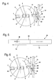
- Fig. 4 shows the cutter disk 6 in Hburghnetrieb.
- the cutter disk 6 is driven in a second direction of rotation 13 about the axis of rotation 5.
- the cutting blades 7 are not in use.
- the cutting of the cutting blade 7 are opposite to the direction of rotation 13.
- the razor 8 come in this direction of rotation 13 into engagement with the shredded material.
- the illustrated by the arrow 17 air flow, which generates the cutter disk 6 during operation, acts opposite to the Schnitzel réelle in the opposite direction.
- a force is exerted on the wind vane 18 in the opposite direction, and the slider 19 is moved in the guide 21 in its other end position.
- the display section 20 indicates the chopping operation.
- Fig. 5 the viewing window 24 is shown.
- the inscription "chopping” is attached and in a second area the inscription "Schnitzeln". If the cutter disk 6 rotates in the second rotational direction 13 for chopping operation, then the display portion 20 on the slider 19 is pressed into the region of the viewing window 24 which bears the inscription "chopping".
- the display section 20 in the other Area of the viewing window 24 is pressed, which carries the inscription "Schnitzel".
- a wind vane in the region of the drive shaft 4.
- An arrangement below the cutter disk 6 can also be provided. In order to avoid contamination of the wind vane, and the arrangement of elements such as gratings or the like., Intercept the dirt may be provided on the wind vane 18.
- driver 33 on the drive shaft 4 or to connect this rotationally fixed to the drive shaft 4.
- FIGS. 7 and 8 Another embodiment of a mode indicator 42 is shown in FIGS FIGS. 7 and 8 shown.
- the in the FIGS. 7 and 8 A chopper shown in sections has a mode switch 41 which is pivotally mounted about a pivot axis 43 is.
- a lever arm 44 On the mode switch 41, a lever arm 44 is arranged, on which a slider 45 is fixed.
- the slider 45 is mounted longitudinally displaceably in the housing 2 with a bearing 46. One end of the slider 45 projects into the area of a viewing window 24 of the mode indicator 42.
- Fig. 7 shows the mode switch 41 in a position for a first direction of rotation, for example in the position for Schnitzel réelle.
- the mode switch 41 presses in this position, the slider 45 in the region of the viewing window 24, so that an end 47 of the slider 45 in the viewing window 24 is visible. This indicates to the operator the operating state, for example the Schnitzel réelle.
- Fig. 8 the mode switch 41 is shown in a second position in which the lever arm 44 pulls the slider 45 down. In this position, the end 47 of the slider 45 in the viewing window 24 is no longer visible. This indicates to the operator a second mode of operation, such as chopping operation.
- the mode switch 41 simultaneously actuates the drive motor 3, which is designed in the embodiment as an electric motor and switches it between the two directions of rotation 13 and 14.
- a mode indicator 52 in which the direction of rotation of the motor is determined electrically, in particular electronically.
- the drive motor 3 is an AC motor which is connected to an AC power source 53.
- the drive motor 3 is connected to a switching device 54, with which the wiring of the drive motor 3 can be changed so that the drive motor 3 rotates in a switching position in a first direction of rotation 14 and in a second switching position in a second direction of rotation 13. This allows the shredder 1 can be switched between the Hußburgburgtrieb and Schnitzel réelle.
- the mode indicator 52 has an evaluation device 55, which determines the wiring of the drive motor 3 electrically or electronically.
- the mode indicator 52 also has a bulb 56, which may be, for example, an incandescent lamp, a diode or the like.
- a light source 56 can be provided which lights up in one of the operating states and remains switched off in the other operating state.
- FIG Fig. 10 Another embodiment of a mode indicator 62 is shown in FIG Fig. 10 shown.
- the mode indicator 62 off Fig. 10 essentially corresponds to the mode indicator 52 off Fig. 9 , Like reference numerals designate like components.
- the mode display 62 also has an evaluation device 55.
- the mode display 62 has a display 66 in which the operating mode is displayed.
- the display 66 may display, for example, an "S" for shred operation and an "H" for shred operation. However, it may also be a display of symbols or the like. Be provided.
- the display 66 may also be an already provided on the shredder display, which is also used for other display operations.
- a mode indicator 72 detects the direction of rotation of the drive shaft 4. It can also be provided to detect the direction of rotation of the cutter disk 6.
- two signal transmitters 73, 74 are arranged on the circumference of the drive shaft 4.
- the signal transmitters 73 and 74 generate different signals.
- the signals can be different lengths, for example.
- the two signal transmitters 73 and 74 are arranged unevenly on the circumference of the drive shaft 4, so that depending on the direction of rotation different distances between the one, for example, the short and the other, for example, give the long signal.
- a signal sensor 75 Radially outside the signal transmitter 73 and 74, a signal sensor 75 is fixed to the housing, which supplies the determined signals to an evaluation device 76, which determines the direction of rotation.
- the determined direction of rotation or the determined operating mode is displayed on a display 77.
- Other types of detection and indication of the direction of rotation of the cutter disc 6 may also be provided. It may be appropriate to connect a mechanical detection of the direction of rotation with an electrical display or an electrical detection with a mechanical display.
Landscapes
- Engineering & Computer Science (AREA)
- Food Science & Technology (AREA)
- Crushing And Pulverization Processes (AREA)
- Food-Manufacturing Devices (AREA)
Priority Applications (4)
| Application Number | Priority Date | Filing Date | Title |
|---|---|---|---|
| ES07013648T ES2351232T3 (es) | 2007-07-12 | 2007-07-12 | Picadora. |
| DE502007005004T DE502007005004D1 (de) | 2007-07-12 | 2007-07-12 | Häcksler |
| AT07013648T ATE480331T1 (de) | 2007-07-12 | 2007-07-12 | Häcksler |
| EP07013648A EP2014369B1 (fr) | 2007-07-12 | 2007-07-12 | Hache |
Applications Claiming Priority (1)
| Application Number | Priority Date | Filing Date | Title |
|---|---|---|---|
| EP07013648A EP2014369B1 (fr) | 2007-07-12 | 2007-07-12 | Hache |
Publications (2)
| Publication Number | Publication Date |
|---|---|
| EP2014369A1 true EP2014369A1 (fr) | 2009-01-14 |
| EP2014369B1 EP2014369B1 (fr) | 2010-09-08 |
Family
ID=38535418
Family Applications (1)
| Application Number | Title | Priority Date | Filing Date |
|---|---|---|---|
| EP07013648A Not-in-force EP2014369B1 (fr) | 2007-07-12 | 2007-07-12 | Hache |
Country Status (4)
| Country | Link |
|---|---|
| EP (1) | EP2014369B1 (fr) |
| AT (1) | ATE480331T1 (fr) |
| DE (1) | DE502007005004D1 (fr) |
| ES (1) | ES2351232T3 (fr) |
Citations (3)
| Publication number | Priority date | Publication date | Assignee | Title |
|---|---|---|---|---|
| DE3527772A1 (de) * | 1985-08-02 | 1987-02-12 | Friedrich Maschke | Vorrichtung zum zerkleinern von abfaellen |
| EP0346661A2 (fr) * | 1988-06-15 | 1989-12-20 | Viking-Umwelttechnik Gesellschaft m.b.H. | Appareil hacheur découpeur |
| EP1466666A2 (fr) * | 2003-04-07 | 2004-10-13 | Robert Bosch GmbH | Broyer de jardinage |
-
2007
- 2007-07-12 AT AT07013648T patent/ATE480331T1/de active
- 2007-07-12 ES ES07013648T patent/ES2351232T3/es active Active
- 2007-07-12 DE DE502007005004T patent/DE502007005004D1/de active Active
- 2007-07-12 EP EP07013648A patent/EP2014369B1/fr not_active Not-in-force
Patent Citations (3)
| Publication number | Priority date | Publication date | Assignee | Title |
|---|---|---|---|---|
| DE3527772A1 (de) * | 1985-08-02 | 1987-02-12 | Friedrich Maschke | Vorrichtung zum zerkleinern von abfaellen |
| EP0346661A2 (fr) * | 1988-06-15 | 1989-12-20 | Viking-Umwelttechnik Gesellschaft m.b.H. | Appareil hacheur découpeur |
| EP1466666A2 (fr) * | 2003-04-07 | 2004-10-13 | Robert Bosch GmbH | Broyer de jardinage |
Also Published As
| Publication number | Publication date |
|---|---|
| DE502007005004D1 (de) | 2010-10-21 |
| ES2351232T3 (es) | 2011-02-01 |
| EP2014369B1 (fr) | 2010-09-08 |
| ATE480331T1 (de) | 2010-09-15 |
Similar Documents
| Publication | Publication Date | Title |
|---|---|---|
| DE602004003264T2 (de) | Sicherungssystem für Maschinen | |
| DE102010044276B4 (de) | Schalteinrichtung für einen Rasenmäher | |
| US6390398B1 (en) | Device capable of shredding paper and sharpening pencil | |
| DE102014003444B4 (de) | Schredder mit interaktiver Schnittstelle | |
| EP2783561B1 (fr) | Appareil de travail automobile | |
| DE202005021450U1 (de) | Sicherheitssystem für Materialzerkleinerer-Eingabeöffnung | |
| EP4072787B1 (fr) | Appareil outil électrique doté d'un moteur et d'un outil rotatif | |
| EP1195202A1 (fr) | Déchiqueteur avec un dispositif de coupe actionné par electromoteur | |
| DE10122407B4 (de) | Mähvorrichtung zum Mähen eines Bereichs neben einem Tragmittel | |
| WO2000068579A1 (fr) | Dispositif d'affichage | |
| DE202020002176U1 (de) | Arbeitsmaschine | |
| EP2014369B1 (fr) | Hache | |
| CH706726A2 (de) | Gerät zum Bearbeiten von Lebensmitteln. | |
| EP2251167B1 (fr) | Dispositif de sécurité pour scies circulaires | |
| DE3335719C1 (de) | Sicherheitsverriegelung fuer Schneidmuehlen | |
| DE112023000825T5 (de) | Akkubetriebene Metallschere | |
| CN109176609A (zh) | 一种电动剪刀 | |
| DE4406675A1 (de) | Vorrichtung zum schneidenden Zerkleinern von Materialien | |
| EP1958223B1 (fr) | Commande de changement de rapport de transmission dotee d'un dispositif de surveillance du changement de rapport | |
| EP2324953A2 (fr) | Affûteuse | |
| EP2564930B1 (fr) | Hache | |
| EP0730934B1 (fr) | Rogneuse avec dispositif d'évacuation des chutes | |
| DE202007018780U1 (de) | Sicherheitsmechanismus für eine Küchenmaschine mit Rührschüssel und Deckel | |
| EP2638794B1 (fr) | Broyeur mobile pour plantes doté d'un système de surveillance du rotor en fonction de la position du couvercle | |
| EP2745676B1 (fr) | Machine-outil comprenant au moins une lame de travail pouvant être entraînée pour exécuter un mouvement de va-et-vient |
Legal Events
| Date | Code | Title | Description |
|---|---|---|---|
| PUAI | Public reference made under article 153(3) epc to a published international application that has entered the european phase |
Free format text: ORIGINAL CODE: 0009012 |
|
| AK | Designated contracting states |
Kind code of ref document: A1 Designated state(s): AT BE BG CH CY CZ DE DK EE ES FI FR GB GR HU IE IS IT LI LT LU LV MC MT NL PL PT RO SE SI SK TR |
|
| AX | Request for extension of the european patent |
Extension state: AL BA HR MK RS |
|
| 17P | Request for examination filed |
Effective date: 20090612 |
|
| AKX | Designation fees paid |
Designated state(s): AT BE DE ES FR GB |
|
| GRAP | Despatch of communication of intention to grant a patent |
Free format text: ORIGINAL CODE: EPIDOSNIGR1 |
|
| GRAS | Grant fee paid |
Free format text: ORIGINAL CODE: EPIDOSNIGR3 |
|
| GRAA | (expected) grant |
Free format text: ORIGINAL CODE: 0009210 |
|
| AK | Designated contracting states |
Kind code of ref document: B1 Designated state(s): AT BE DE ES FR GB |
|
| REG | Reference to a national code |
Ref country code: GB Ref legal event code: FG4D Free format text: NOT ENGLISH |
|
| REF | Corresponds to: |
Ref document number: 502007005004 Country of ref document: DE Date of ref document: 20101021 Kind code of ref document: P |
|
| REG | Reference to a national code |
Ref country code: ES Ref legal event code: FG2A Effective date: 20110120 |
|
| PLBE | No opposition filed within time limit |
Free format text: ORIGINAL CODE: 0009261 |
|
| STAA | Information on the status of an ep patent application or granted ep patent |
Free format text: STATUS: NO OPPOSITION FILED WITHIN TIME LIMIT |
|
| 26N | No opposition filed |
Effective date: 20110609 |
|
| REG | Reference to a national code |
Ref country code: DE Ref legal event code: R097 Ref document number: 502007005004 Country of ref document: DE Effective date: 20110609 |
|
| REG | Reference to a national code |
Ref country code: FR Ref legal event code: PLFP Year of fee payment: 10 |
|
| REG | Reference to a national code |
Ref country code: FR Ref legal event code: PLFP Year of fee payment: 11 |
|
| REG | Reference to a national code |
Ref country code: FR Ref legal event code: PLFP Year of fee payment: 12 |
|
| REG | Reference to a national code |
Ref country code: DE Ref legal event code: R082 Ref document number: 502007005004 Country of ref document: DE Representative=s name: PATENTANWAELTE DIPL.-ING. W. JACKISCH & PARTNE, DE Ref country code: DE Ref legal event code: R082 Ref document number: 502007005004 Country of ref document: DE Representative=s name: PATENTANWAELTE DIPL.-ING. WALTER JACKISCH & PA, DE Ref country code: DE Ref legal event code: R081 Ref document number: 502007005004 Country of ref document: DE Owner name: ANDREAS STIHL AG & CO. KG, DE Free format text: FORMER OWNER: VIKING GMBH, LANGKAMPFEN, AT |
|
| REG | Reference to a national code |
Ref country code: ES Ref legal event code: PC2A Owner name: ANDREAS STIHL AG & CO. KG Effective date: 20181008 |
|
| REG | Reference to a national code |
Ref country code: GB Ref legal event code: 732E Free format text: REGISTERED BETWEEN 20180927 AND 20181005 |
|
| REG | Reference to a national code |
Ref country code: BE Ref legal event code: PD Owner name: ANDREAS STIHL AG & CO. KG; DE Free format text: DETAILS ASSIGNMENT: CHANGE OF OWNER(S), CESSION; FORMER OWNER NAME: VIKING GMBH Effective date: 20181009 |
|
| REG | Reference to a national code |
Ref country code: AT Ref legal event code: PC Ref document number: 480331 Country of ref document: AT Kind code of ref document: T Owner name: ANDREAS STIHL AG & CO. KG, DE Effective date: 20181203 |
|
| PGFP | Annual fee paid to national office [announced via postgrant information from national office to epo] |
Ref country code: GB Payment date: 20230725 Year of fee payment: 17 Ref country code: ES Payment date: 20230816 Year of fee payment: 17 Ref country code: AT Payment date: 20230718 Year of fee payment: 17 |
|
| PGFP | Annual fee paid to national office [announced via postgrant information from national office to epo] |
Ref country code: DE Payment date: 20240730 Year of fee payment: 18 |
|
| PGFP | Annual fee paid to national office [announced via postgrant information from national office to epo] |
Ref country code: BE Payment date: 20240725 Year of fee payment: 18 |
|
| PGFP | Annual fee paid to national office [announced via postgrant information from national office to epo] |
Ref country code: FR Payment date: 20240725 Year of fee payment: 18 |
|
| REG | Reference to a national code |
Ref country code: AT Ref legal event code: MM01 Ref document number: 480331 Country of ref document: AT Kind code of ref document: T Effective date: 20240712 |
|
| GBPC | Gb: european patent ceased through non-payment of renewal fee |
Effective date: 20240712 |
|
| PG25 | Lapsed in a contracting state [announced via postgrant information from national office to epo] |
Ref country code: AT Free format text: LAPSE BECAUSE OF NON-PAYMENT OF DUE FEES Effective date: 20240712 |
|
| PG25 | Lapsed in a contracting state [announced via postgrant information from national office to epo] |
Ref country code: GB Free format text: LAPSE BECAUSE OF NON-PAYMENT OF DUE FEES Effective date: 20240712 |
|
| REG | Reference to a national code |
Ref country code: ES Ref legal event code: FD2A Effective date: 20250828 |
|
| PG25 | Lapsed in a contracting state [announced via postgrant information from national office to epo] |
Ref country code: ES Free format text: LAPSE BECAUSE OF NON-PAYMENT OF DUE FEES Effective date: 20240713 |
|
| REG | Reference to a national code |
Ref country code: DE Ref legal event code: R119 Ref document number: 502007005004 Country of ref document: DE |
|
| REG | Reference to a national code |
Ref country code: BE Ref legal event code: MM Effective date: 20250731 |
|
| PG25 | Lapsed in a contracting state [announced via postgrant information from national office to epo] |
Ref country code: DE Free format text: LAPSE BECAUSE OF NON-PAYMENT OF DUE FEES Effective date: 20260203 |
|
| PG25 | Lapsed in a contracting state [announced via postgrant information from national office to epo] |
Ref country code: BE Free format text: LAPSE BECAUSE OF NON-PAYMENT OF DUE FEES Effective date: 20250731 |
|
| PG25 | Lapsed in a contracting state [announced via postgrant information from national office to epo] |
Ref country code: FR Free format text: LAPSE BECAUSE OF NON-PAYMENT OF DUE FEES Effective date: 20250731 |