EP2014382B1 - Rohrbiegemaschine - Google Patents
Rohrbiegemaschine Download PDFInfo
- Publication number
- EP2014382B1 EP2014382B1 EP08011762A EP08011762A EP2014382B1 EP 2014382 B1 EP2014382 B1 EP 2014382B1 EP 08011762 A EP08011762 A EP 08011762A EP 08011762 A EP08011762 A EP 08011762A EP 2014382 B1 EP2014382 B1 EP 2014382B1
- Authority
- EP
- European Patent Office
- Prior art keywords
- tube
- bending
- bent
- machine
- positioning
- Prior art date
- Legal status (The legal status is an assumption and is not a legal conclusion. Google has not performed a legal analysis and makes no representation as to the accuracy of the status listed.)
- Not-in-force
Links
Images

Classifications
-
- B—PERFORMING OPERATIONS; TRANSPORTING
- B21—MECHANICAL METAL-WORKING WITHOUT ESSENTIALLY REMOVING MATERIAL; PUNCHING METAL
- B21D—WORKING OR PROCESSING OF SHEET METAL OR METAL TUBES, RODS OR PROFILES WITHOUT ESSENTIALLY REMOVING MATERIAL; PUNCHING METAL
- B21D7/00—Bending rods, profiles, or tubes
- B21D7/02—Bending rods, profiles, or tubes over a stationary forming member; by use of a swinging forming member or abutment
- B21D7/024—Bending rods, profiles, or tubes over a stationary forming member; by use of a swinging forming member or abutment by a swinging forming member
-
- B—PERFORMING OPERATIONS; TRANSPORTING
- B21—MECHANICAL METAL-WORKING WITHOUT ESSENTIALLY REMOVING MATERIAL; PUNCHING METAL
- B21D—WORKING OR PROCESSING OF SHEET METAL OR METAL TUBES, RODS OR PROFILES WITHOUT ESSENTIALLY REMOVING MATERIAL; PUNCHING METAL
- B21D7/00—Bending rods, profiles, or tubes
- B21D7/12—Bending rods, profiles, or tubes with program control
Definitions
- the present invention relates to a machine for bending tubes of any length (short, medium or long) according to the preamble of claim 1 (see US-B1-6 434 995 ), without having to withdraw the tube to be bent, in order to effect curves with a different radius and/or in different bending planes.
- the machine which is the subject of the present invention is also suitable for bending tubes designated as hybrid, that is to say tubes formed from lengths of metal and lengths of rubber or other non-metallic material.
- Tube-bending machines which bend tubes by setting about the bending starting from one end of the tube to be bent and keeping the other end of said tube in the positioning device.
- Tubes bent with said known machines have the disadvantage of oscillating and/or undergoing deformation subsequently to bending because they are left lacking adequate support, in a so-called overhanging position, that is to say restrained at a single point and subjected to the force of gravity.
- the known tube-bending machines In relation to the bending of tubes generally designated hybrid, that is to say tubes formed from lengths of metal and lengths of rubber or other non-metallic material, the known tube-bending machines have great difficulty in bending said hybrid tubes, because said machines set about bending the tube starting from just one end of said tube, and the bending devices can easily touch the non-metallic parts of the tube, with the risk of damaging it.
- an orbital machine for bending long tubes is also known, described in document US 7.093.475 .
- Said machine includes a bending head mounted on a U-shaped arm which rotates around the horizontal axis of the tube to be bent.
- the machine described in said document has the disadvantage of being able to manipulate tubes of small size because the weight of the head mounted on the above-mentioned U-shaped arm must be small for structural reasons relating to the shape of said arm.
- the length of the tubes to be bent is anyway limited by the breadth of the U which constitutes the above-mentioned arm, the overall dimensions of the bent tube being limited by the breadth of the U formed by the above-mentioned arm.
- An object of the present invention is to create a machine for bending metal or hybrid tubes, that is to say tubes formed from lengths of metal and lengths of rubber or other non-metallic material, of any size and length, with characteristics which are such as to be able to overcome the disadvantages mentioned with reference to the known art.
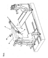
- no. (1) indicates a machine for bending tubes, consisting of a supporting base (2) which supports a positioning device (3) for the tube to be bent (7) of wholly metallic or hybrid type, that is to say formed from lengths of metal and lengths of rubber or other non-metallic material, by one or more devices (4) for bending the tube (7) to be bent.
- Said positioning device (3) consists of a turret (5) and a positioning arm (6).
- Said machine also includes means known to persons skilled in the art for the purpose of making the positioning device (3), by means of the translation of turret (5) and/or device (4), take up mutual positions for the purpose of allowing said device (4) to be moved, according to methods known to persons skilled in the art, for the purpose of bending said tube (7) on the basis of the preset work programme.
- Said Figure 1 also shows the positioning device (3) provided with means (8) for rotating the positioning arm (6) through up to 360° around the central axis (Y) of the tube (7) to be bent, so as to be able advantageously to bend said tube (7), particularly of hybrid type, in various bending planes having in common said central axis (Y), having among other things the possibility of locking the tube in the intermediate area and being able to start indifferently from either of its ends, thus overcoming the disadvantages of the known machines.
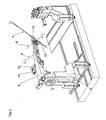
- FIG. 2 shows the machine of fig. 1 , highlighting the positioning arm (6) equipped with a locking device (9) for the tube (7) to be bent.
- Said locking device (9) is provided with means (10) for rotating through up to 360° around a fulcrum (F) so as to rotate said tube (7) for the purpose of being able to bend either end of said tube (7) alternatively by means of device (4) on the basis of a preset work programme.
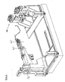
- Figure 3 shows the machine of figure 1 , demonstrating another embodiment according to which the positioning arm (6), equipped with two locking devices (12) and (13) for the tube (7) to be bent, is provided with means (10) and (11) for rotating through up to 360° around fulcrum (F) and fulcrum (G) so as to rotate said tube (7) for the purpose of being able to bend either end of said tube (7) alternatively and/or an intermediate part of said tube by means of device (4) on the basis of a preset work programme.
- Figure 4 shows the machine of fig. 1 , equipped with a further bending device (14) capable of moving and being moved by known movement means. Equipping machine 1 with further possibilities of bending enables a considerable increase in the possibilities of bending said tube (7).
- the machine 1 can be susceptible of numerous variations particularly as regards the positioning of the elements without thereby departing from the scope of the invention as defined by the appended claims.
Landscapes
- Engineering & Computer Science (AREA)
- Mechanical Engineering (AREA)
- Bending Of Plates, Rods, And Pipes (AREA)
- Shaping Of Tube Ends By Bending Or Straightening (AREA)
- Coating With Molten Metal (AREA)
- Formation And Processing Of Food Products (AREA)
- Soil Working Implements (AREA)
Claims (3)
- eine Rohrbiegemaschine (1), Folgendes umfassend:- ein Untergestell (2);- eine Positioniervorrichtung (3) für das zu biegende Rohr (7),- mindestens eine Vorrichtung (4) zum Biegen des zu biegenden Rohrs (7),- Mittel, um die Positioniervorrichtung (3) und die Vorrichtung (4) zum Biegen des besagten Rohrs (7) in zueinander passende Positionen zum Biegen des besagten Rohrs (7) zu bringen, wobei die besagte Positioniervorrichtung (3) einem Drehhalterbock (5) und einen Positionierarm (6) umfasst und mit einem Mittel (8) ausgestattet ist, das dafür geeignet ist, den besagten Positionierarm (6) um 360° um die Mittelachse (Y) des zu biegenden Rohrs (7) zu drehen, damit das besagte Rohr (7) positioniert werden kann, um es mithilfe der besagten Vorrichtung (4) in verschiedenen Biegeebenen zu biegen; dadurch gekennzeichnet, dass der besagte Positionierarm (6) mit mindestens einer(1) Arretierungsvorrichtung (9) für das zu biegende Rohr (7) sowie mit einem Mittel (10) ausgestattet ist, das dafür geeignet ist, die besagte Arretierungsvorrichtung (9) um bis zu 360° um eine Achse (F) zu drehen, damit das besagte Rohr (7) gedreht werden kann, um wahlweise eines seiner beiden Enden mithilfe der besagten Vorrichtung (4) zu biegen;
- eine Rohrbiegemaschine (1) gemäß Anspruch; dadurch gekennzeichnet, dass der besagte Positionierarm (6) mit zwei Arretierungsvorrichtungen (12) und (13) für das zu biegende Rohr (7) sowie mit Mitteln (10) und (11) ausgestattet ist, die geeignet sind, die besagten Vorrichtungen um bis zu 360° um die Achse (F) beziehungsweise die Achse (G) zu drehen, damit das besagte Rohr (7) gedreht werden kann, um wahlweise eines seiner beiden Enden mithilfe der besagten Vorrichtung (4) zu biegen;
- eine Rohrbiegemaschine (1) gemäß einem der vorstehenden Ansprüche; dadurch gekennzeichnet, dass sie mindestens eine zweite Biegevorrichtung (14) umfasst.
Applications Claiming Priority (1)
| Application Number | Priority Date | Filing Date | Title |
|---|---|---|---|
| IT001355A ITMI20071355A1 (it) | 2007-07-09 | 2007-07-09 | Macchina curvatubi |
Publications (2)
| Publication Number | Publication Date |
|---|---|
| EP2014382A1 EP2014382A1 (de) | 2009-01-14 |
| EP2014382B1 true EP2014382B1 (de) | 2010-10-27 |
Family
ID=39929889
Family Applications (1)
| Application Number | Title | Priority Date | Filing Date |
|---|---|---|---|
| EP08011762A Not-in-force EP2014382B1 (de) | 2007-07-09 | 2008-06-30 | Rohrbiegemaschine |
Country Status (5)
| Country | Link |
|---|---|
| US (1) | US20090173127A1 (de) |
| EP (1) | EP2014382B1 (de) |
| AT (1) | ATE485900T1 (de) |
| DE (1) | DE602008003160D1 (de) |
| IT (1) | ITMI20071355A1 (de) |
Families Citing this family (7)
| Publication number | Priority date | Publication date | Assignee | Title |
|---|---|---|---|---|
| TW201505735A (zh) * | 2013-05-17 | 2015-02-16 | Opton Kk | 彎曲加工系統 |
| JP6619560B2 (ja) * | 2015-04-15 | 2019-12-11 | 株式会社オプトン | 曲げ加工装置 |
| EP3238850B1 (de) * | 2016-04-27 | 2019-10-23 | Advanced Orthodontic Solutions | Drahtbiegemaschine |
| DE102018128903A1 (de) * | 2018-11-16 | 2020-05-20 | Wafios Aktiengesellschaft | Vorrichtung zum Biegen stabförmiger Werkstücke |
| CN109530509B (zh) * | 2018-12-04 | 2020-01-31 | 中国科学院宁波材料技术与工程研究所 | 直线型钛合金医用内固定板自动塑形机构 |
| CN109549699B (zh) * | 2018-12-04 | 2021-05-25 | 中南大学湘雅医院 | 弧线型钛合金医用内固定板自动塑形机构 |
| IT202100009389A1 (it) * | 2021-04-14 | 2022-10-14 | Op Srl | Macchina per lavorazioni di deformazione di un tubo e/o di un componente sul tubo |
Family Cites Families (6)
| Publication number | Priority date | Publication date | Assignee | Title |
|---|---|---|---|---|
| US6434995B1 (en) * | 1999-10-15 | 2002-08-20 | Usui Kokusai Sangyo Kaisha Limited | Method of bending small diameter metal pipe and its apparatus |
| JP4319314B2 (ja) * | 2000-01-31 | 2009-08-26 | 株式会社オプトン | 曲げ加工装置 |
| FR2859653B1 (fr) | 2003-09-12 | 2006-03-17 | Silfax Sa | Machine orbitale pour le cintrage des tubes |
| JP4591908B2 (ja) * | 2003-12-15 | 2010-12-01 | 臼井国際産業株式会社 | パイプの曲げ加工装置 |
| JP5090636B2 (ja) * | 2004-09-27 | 2012-12-05 | 株式会社オプトン | 曲げ加工装置 |
| DE102004048036A1 (de) * | 2004-09-28 | 2006-04-06 | Ras Reinhardt Maschinenbau Gmbh | Biegeeinrichtung |
-
2007
- 2007-07-09 IT IT001355A patent/ITMI20071355A1/it unknown
-
2008
- 2008-06-30 AT AT08011762T patent/ATE485900T1/de not_active IP Right Cessation
- 2008-06-30 DE DE602008003160T patent/DE602008003160D1/de active Active
- 2008-06-30 EP EP08011762A patent/EP2014382B1/de not_active Not-in-force
- 2008-07-07 US US12/168,574 patent/US20090173127A1/en not_active Abandoned
Also Published As
| Publication number | Publication date |
|---|---|
| ITMI20071355A1 (it) | 2009-01-10 |
| US20090173127A1 (en) | 2009-07-09 |
| ATE485900T1 (de) | 2010-11-15 |
| EP2014382A1 (de) | 2009-01-14 |
| DE602008003160D1 (de) | 2010-12-09 |
Similar Documents
| Publication | Publication Date | Title |
|---|---|---|
| EP2014382B1 (de) | Rohrbiegemaschine | |
| JP6250994B2 (ja) | 自在軸受けブレード付きパネル曲げマシン | |
| JP5505824B2 (ja) | 曲げ加工装置 | |
| CN103507071A (zh) | 机器人系统和用于制造装配件的方法 | |
| US20150040634A1 (en) | Bending machine having a bending head that is movable about a stationary bending shank | |
| RU2628591C2 (ru) | Устройство и способ для загиба кромок с использованием ролика | |
| JP6101454B2 (ja) | ワーク加工装置及び該ワーク加工装置における金型の移動方法 | |
| JP5389522B2 (ja) | コイル成形方法及びコイル成形装置 | |
| JP2010222138A (ja) | アウトリガ装置 | |
| US10758958B2 (en) | Roller hemming processing method and roller hemming processing device | |
| JP6154229B2 (ja) | シールド掘進機のセグメント把持装置 | |
| JP2012066273A (ja) | 加熱ヘッド | |
| EP1494825B1 (de) | Verfahren und vorrichtung zum biegen von drahtstangen, draht, rohren und ähnlichem material mit prismatischem querschnit | |
| JP2811281B2 (ja) | 細径金属管の曲げ加工装置 | |
| JP2008234891A (ja) | 圧縮ヘッドの支持器 | |
| WO2015166875A1 (ja) | タイヤ支持機構及びタイヤチェンジャ | |
| JP5505823B2 (ja) | 曲げ加工装置及び曲げ加工方法 | |
| JPH06142775A (ja) | ロールベンダ | |
| KR102583197B1 (ko) | 유리 튜브 이중 방향 신장 방법, 도구, 및 미세 조정 시스템 | |
| KR101117162B1 (ko) | 벤딩장치 | |
| JP5424734B2 (ja) | 加熱ヘッド | |
| CN107571451A (zh) | 一种折弯机或者掰断机 | |
| JP4993738B2 (ja) | 電車線用ハンガの曲げ加工装置 | |
| CN101279383A (zh) | 用于焊接管的飞刀切割装置 | |
| JP6554004B2 (ja) | 曲げ加工装置、曲げ加工方法、及び、曲げ加工用コマ |
Legal Events
| Date | Code | Title | Description |
|---|---|---|---|
| PUAI | Public reference made under article 153(3) epc to a published international application that has entered the european phase |
Free format text: ORIGINAL CODE: 0009012 |
|
| 17P | Request for examination filed |
Effective date: 20080702 |
|
| AK | Designated contracting states |
Kind code of ref document: A1 Designated state(s): AT BE BG CH CY CZ DE DK EE ES FI FR GB GR HR HU IE IS IT LI LT LU LV MC MT NL NO PL PT RO SE SI SK TR |
|
| AX | Request for extension of the european patent |
Extension state: AL BA MK RS |
|
| AKX | Designation fees paid |
Designated state(s): AT BE BG CH CY CZ DE DK EE ES FI FR GB GR HR HU IE IS IT LI LT LU LV MC MT NL NO PL PT RO SE SI SK TR |
|
| GRAP | Despatch of communication of intention to grant a patent |
Free format text: ORIGINAL CODE: EPIDOSNIGR1 |
|
| GRAS | Grant fee paid |
Free format text: ORIGINAL CODE: EPIDOSNIGR3 |
|
| GRAA | (expected) grant |
Free format text: ORIGINAL CODE: 0009210 |
|
| AK | Designated contracting states |
Kind code of ref document: B1 Designated state(s): AT BE BG CH CY CZ DE DK EE ES FI FR GB GR HR HU IE IS IT LI LT LU LV MC MT NL NO PL PT RO SE SI SK TR |
|
| REG | Reference to a national code |
Ref country code: GB Ref legal event code: FG4D |
|
| REG | Reference to a national code |
Ref country code: CH Ref legal event code: EP |
|
| REG | Reference to a national code |
Ref country code: IE Ref legal event code: FG4D |
|
| REF | Corresponds to: |
Ref document number: 602008003160 Country of ref document: DE Date of ref document: 20101209 Kind code of ref document: P |
|
| REG | Reference to a national code |
Ref country code: NL Ref legal event code: VDEP Effective date: 20101027 |
|
| LTIE | Lt: invalidation of european patent or patent extension |
Effective date: 20101027 |
|
| PG25 | Lapsed in a contracting state [announced via postgrant information from national office to epo] |
Ref country code: NO Free format text: LAPSE BECAUSE OF FAILURE TO SUBMIT A TRANSLATION OF THE DESCRIPTION OR TO PAY THE FEE WITHIN THE PRESCRIBED TIME-LIMIT Effective date: 20110127 Ref country code: LT Free format text: LAPSE BECAUSE OF FAILURE TO SUBMIT A TRANSLATION OF THE DESCRIPTION OR TO PAY THE FEE WITHIN THE PRESCRIBED TIME-LIMIT Effective date: 20101027 |
|
| PG25 | Lapsed in a contracting state [announced via postgrant information from national office to epo] |
Ref country code: SE Free format text: LAPSE BECAUSE OF FAILURE TO SUBMIT A TRANSLATION OF THE DESCRIPTION OR TO PAY THE FEE WITHIN THE PRESCRIBED TIME-LIMIT Effective date: 20101027 Ref country code: HR Free format text: LAPSE BECAUSE OF FAILURE TO SUBMIT A TRANSLATION OF THE DESCRIPTION OR TO PAY THE FEE WITHIN THE PRESCRIBED TIME-LIMIT Effective date: 20101027 Ref country code: BG Free format text: LAPSE BECAUSE OF FAILURE TO SUBMIT A TRANSLATION OF THE DESCRIPTION OR TO PAY THE FEE WITHIN THE PRESCRIBED TIME-LIMIT Effective date: 20110127 Ref country code: LV Free format text: LAPSE BECAUSE OF FAILURE TO SUBMIT A TRANSLATION OF THE DESCRIPTION OR TO PAY THE FEE WITHIN THE PRESCRIBED TIME-LIMIT Effective date: 20101027 Ref country code: AT Free format text: LAPSE BECAUSE OF FAILURE TO SUBMIT A TRANSLATION OF THE DESCRIPTION OR TO PAY THE FEE WITHIN THE PRESCRIBED TIME-LIMIT Effective date: 20101027 Ref country code: FI Free format text: LAPSE BECAUSE OF FAILURE TO SUBMIT A TRANSLATION OF THE DESCRIPTION OR TO PAY THE FEE WITHIN THE PRESCRIBED TIME-LIMIT Effective date: 20101027 Ref country code: SI Free format text: LAPSE BECAUSE OF FAILURE TO SUBMIT A TRANSLATION OF THE DESCRIPTION OR TO PAY THE FEE WITHIN THE PRESCRIBED TIME-LIMIT Effective date: 20101027 Ref country code: NL Free format text: LAPSE BECAUSE OF FAILURE TO SUBMIT A TRANSLATION OF THE DESCRIPTION OR TO PAY THE FEE WITHIN THE PRESCRIBED TIME-LIMIT Effective date: 20101027 Ref country code: PT Free format text: LAPSE BECAUSE OF FAILURE TO SUBMIT A TRANSLATION OF THE DESCRIPTION OR TO PAY THE FEE WITHIN THE PRESCRIBED TIME-LIMIT Effective date: 20110228 Ref country code: IS Free format text: LAPSE BECAUSE OF FAILURE TO SUBMIT A TRANSLATION OF THE DESCRIPTION OR TO PAY THE FEE WITHIN THE PRESCRIBED TIME-LIMIT Effective date: 20110227 |
|
| PG25 | Lapsed in a contracting state [announced via postgrant information from national office to epo] |
Ref country code: GR Free format text: LAPSE BECAUSE OF FAILURE TO SUBMIT A TRANSLATION OF THE DESCRIPTION OR TO PAY THE FEE WITHIN THE PRESCRIBED TIME-LIMIT Effective date: 20110128 Ref country code: BE Free format text: LAPSE BECAUSE OF FAILURE TO SUBMIT A TRANSLATION OF THE DESCRIPTION OR TO PAY THE FEE WITHIN THE PRESCRIBED TIME-LIMIT Effective date: 20101027 |
|
| PG25 | Lapsed in a contracting state [announced via postgrant information from national office to epo] |
Ref country code: CZ Free format text: LAPSE BECAUSE OF FAILURE TO SUBMIT A TRANSLATION OF THE DESCRIPTION OR TO PAY THE FEE WITHIN THE PRESCRIBED TIME-LIMIT Effective date: 20101027 Ref country code: ES Free format text: LAPSE BECAUSE OF FAILURE TO SUBMIT A TRANSLATION OF THE DESCRIPTION OR TO PAY THE FEE WITHIN THE PRESCRIBED TIME-LIMIT Effective date: 20110207 Ref country code: EE Free format text: LAPSE BECAUSE OF FAILURE TO SUBMIT A TRANSLATION OF THE DESCRIPTION OR TO PAY THE FEE WITHIN THE PRESCRIBED TIME-LIMIT Effective date: 20101027 |
|
| PG25 | Lapsed in a contracting state [announced via postgrant information from national office to epo] |
Ref country code: RO Free format text: LAPSE BECAUSE OF FAILURE TO SUBMIT A TRANSLATION OF THE DESCRIPTION OR TO PAY THE FEE WITHIN THE PRESCRIBED TIME-LIMIT Effective date: 20101027 Ref country code: SK Free format text: LAPSE BECAUSE OF FAILURE TO SUBMIT A TRANSLATION OF THE DESCRIPTION OR TO PAY THE FEE WITHIN THE PRESCRIBED TIME-LIMIT Effective date: 20101027 Ref country code: PL Free format text: LAPSE BECAUSE OF FAILURE TO SUBMIT A TRANSLATION OF THE DESCRIPTION OR TO PAY THE FEE WITHIN THE PRESCRIBED TIME-LIMIT Effective date: 20101027 Ref country code: DK Free format text: LAPSE BECAUSE OF FAILURE TO SUBMIT A TRANSLATION OF THE DESCRIPTION OR TO PAY THE FEE WITHIN THE PRESCRIBED TIME-LIMIT Effective date: 20101027 |
|
| PLBE | No opposition filed within time limit |
Free format text: ORIGINAL CODE: 0009261 |
|
| STAA | Information on the status of an ep patent application or granted ep patent |
Free format text: STATUS: NO OPPOSITION FILED WITHIN TIME LIMIT |
|
| 26N | No opposition filed |
Effective date: 20110728 |
|
| REG | Reference to a national code |
Ref country code: DE Ref legal event code: R097 Ref document number: 602008003160 Country of ref document: DE Effective date: 20110728 |
|
| PG25 | Lapsed in a contracting state [announced via postgrant information from national office to epo] |
Ref country code: IT Free format text: LAPSE BECAUSE OF FAILURE TO SUBMIT A TRANSLATION OF THE DESCRIPTION OR TO PAY THE FEE WITHIN THE PRESCRIBED TIME-LIMIT Effective date: 20101027 Ref country code: MT Free format text: LAPSE BECAUSE OF FAILURE TO SUBMIT A TRANSLATION OF THE DESCRIPTION OR TO PAY THE FEE WITHIN THE PRESCRIBED TIME-LIMIT Effective date: 20101027 |
|
| REG | Reference to a national code |
Ref country code: FR Ref legal event code: ST Effective date: 20120229 |
|
| REG | Reference to a national code |
Ref country code: IE Ref legal event code: MM4A |
|
| PG25 | Lapsed in a contracting state [announced via postgrant information from national office to epo] |
Ref country code: IE Free format text: LAPSE BECAUSE OF NON-PAYMENT OF DUE FEES Effective date: 20110630 Ref country code: FR Free format text: LAPSE BECAUSE OF NON-PAYMENT OF DUE FEES Effective date: 20110630 |
|
| REG | Reference to a national code |
Ref country code: CH Ref legal event code: PL |
|
| REG | Reference to a national code |
Ref country code: CH Ref legal event code: PL |
|
| GBPC | Gb: european patent ceased through non-payment of renewal fee |
Effective date: 20120630 |
|
| PG25 | Lapsed in a contracting state [announced via postgrant information from national office to epo] |
Ref country code: MC Free format text: LAPSE BECAUSE OF NON-PAYMENT OF DUE FEES Effective date: 20110630 Ref country code: CH Free format text: LAPSE BECAUSE OF NON-PAYMENT OF DUE FEES Effective date: 20120630 Ref country code: GB Free format text: LAPSE BECAUSE OF NON-PAYMENT OF DUE FEES Effective date: 20120630 Ref country code: LI Free format text: LAPSE BECAUSE OF NON-PAYMENT OF DUE FEES Effective date: 20120630 |
|
| PG25 | Lapsed in a contracting state [announced via postgrant information from national office to epo] |
Ref country code: LU Free format text: LAPSE BECAUSE OF NON-PAYMENT OF DUE FEES Effective date: 20110630 Ref country code: CY Free format text: LAPSE BECAUSE OF FAILURE TO SUBMIT A TRANSLATION OF THE DESCRIPTION OR TO PAY THE FEE WITHIN THE PRESCRIBED TIME-LIMIT Effective date: 20101027 |
|
| PG25 | Lapsed in a contracting state [announced via postgrant information from national office to epo] |
Ref country code: TR Free format text: LAPSE BECAUSE OF FAILURE TO SUBMIT A TRANSLATION OF THE DESCRIPTION OR TO PAY THE FEE WITHIN THE PRESCRIBED TIME-LIMIT Effective date: 20101027 |
|
| PG25 | Lapsed in a contracting state [announced via postgrant information from national office to epo] |
Ref country code: HU Free format text: LAPSE BECAUSE OF FAILURE TO SUBMIT A TRANSLATION OF THE DESCRIPTION OR TO PAY THE FEE WITHIN THE PRESCRIBED TIME-LIMIT Effective date: 20101027 |
|
| PGFP | Annual fee paid to national office [announced via postgrant information from national office to epo] |
Ref country code: DE Payment date: 20190627 Year of fee payment: 12 |
|
| REG | Reference to a national code |
Ref country code: DE Ref legal event code: R119 Ref document number: 602008003160 Country of ref document: DE |
|
| PG25 | Lapsed in a contracting state [announced via postgrant information from national office to epo] |
Ref country code: DE Free format text: LAPSE BECAUSE OF NON-PAYMENT OF DUE FEES Effective date: 20210101 |