EP2014427A2 - Procédé et dispositif destinés à sectionner des couches de papiers transportées en continu - Google Patents
Procédé et dispositif destinés à sectionner des couches de papiers transportées en continu Download PDFInfo
- Publication number
- EP2014427A2 EP2014427A2 EP20080405172 EP08405172A EP2014427A2 EP 2014427 A2 EP2014427 A2 EP 2014427A2 EP 20080405172 EP20080405172 EP 20080405172 EP 08405172 A EP08405172 A EP 08405172A EP 2014427 A2 EP2014427 A2 EP 2014427A2
- Authority
- EP
- European Patent Office
- Prior art keywords
- cutting
- edges
- disc
- paper layers
- blade
- Prior art date
- Legal status (The legal status is an assumption and is not a legal conclusion. Google has not performed a legal analysis and makes no representation as to the accuracy of the status listed.)
- Granted
Links
- 238000000034 method Methods 0.000 title claims abstract description 36
- 238000005520 cutting process Methods 0.000 claims abstract description 303
- 230000001360 synchronised effect Effects 0.000 claims abstract description 8
- 239000002699 waste material Substances 0.000 claims abstract description 8
- 238000000926 separation method Methods 0.000 claims description 14
- 238000010008 shearing Methods 0.000 claims 2
- 238000009413 insulation Methods 0.000 abstract 1
- 238000003825 pressing Methods 0.000 description 7
- 230000008901 benefit Effects 0.000 description 3
- 238000002474 experimental method Methods 0.000 description 2
- 238000000227 grinding Methods 0.000 description 2
- 238000004519 manufacturing process Methods 0.000 description 2
- 239000000463 material Substances 0.000 description 2
- 238000009966 trimming Methods 0.000 description 2
- 230000003247 decreasing effect Effects 0.000 description 1
- 238000006073 displacement reaction Methods 0.000 description 1
- 238000005516 engineering process Methods 0.000 description 1
- 238000003754 machining Methods 0.000 description 1
- 238000003801 milling Methods 0.000 description 1
- 238000013138 pruning Methods 0.000 description 1
- 239000007787 solid Substances 0.000 description 1
- 125000006850 spacer group Chemical group 0.000 description 1
- 238000011144 upstream manufacturing Methods 0.000 description 1
Images



Classifications
-
- B—PERFORMING OPERATIONS; TRANSPORTING
- B26—HAND CUTTING TOOLS; CUTTING; SEVERING
- B26D—CUTTING; DETAILS COMMON TO MACHINES FOR PERFORATING, PUNCHING, CUTTING-OUT, STAMPING-OUT OR SEVERING
- B26D1/00—Cutting through work characterised by the nature or movement of the cutting member or particular materials not otherwise provided for; Apparatus or machines therefor; Cutting members therefor
- B26D1/0006—Cutting members therefor
-
- B—PERFORMING OPERATIONS; TRANSPORTING
- B26—HAND CUTTING TOOLS; CUTTING; SEVERING
- B26D—CUTTING; DETAILS COMMON TO MACHINES FOR PERFORATING, PUNCHING, CUTTING-OUT, STAMPING-OUT OR SEVERING
- B26D1/00—Cutting through work characterised by the nature or movement of the cutting member or particular materials not otherwise provided for; Apparatus or machines therefor; Cutting members therefor
- B26D1/01—Cutting through work characterised by the nature or movement of the cutting member or particular materials not otherwise provided for; Apparatus or machines therefor; Cutting members therefor involving a cutting member which does not travel with the work
- B26D1/12—Cutting through work characterised by the nature or movement of the cutting member or particular materials not otherwise provided for; Apparatus or machines therefor; Cutting members therefor involving a cutting member which does not travel with the work having a cutting member moving about an axis
- B26D1/25—Cutting through work characterised by the nature or movement of the cutting member or particular materials not otherwise provided for; Apparatus or machines therefor; Cutting members therefor involving a cutting member which does not travel with the work having a cutting member moving about an axis with a non-circular cutting member
- B26D1/26—Cutting through work characterised by the nature or movement of the cutting member or particular materials not otherwise provided for; Apparatus or machines therefor; Cutting members therefor involving a cutting member which does not travel with the work having a cutting member moving about an axis with a non-circular cutting member moving about an axis substantially perpendicular to the line of cut
- B26D1/28—Cutting through work characterised by the nature or movement of the cutting member or particular materials not otherwise provided for; Apparatus or machines therefor; Cutting members therefor involving a cutting member which does not travel with the work having a cutting member moving about an axis with a non-circular cutting member moving about an axis substantially perpendicular to the line of cut and rotating continuously in one direction during cutting
-
- B—PERFORMING OPERATIONS; TRANSPORTING
- B26—HAND CUTTING TOOLS; CUTTING; SEVERING
- B26D—CUTTING; DETAILS COMMON TO MACHINES FOR PERFORATING, PUNCHING, CUTTING-OUT, STAMPING-OUT OR SEVERING
- B26D1/00—Cutting through work characterised by the nature or movement of the cutting member or particular materials not otherwise provided for; Apparatus or machines therefor; Cutting members therefor
- B26D1/01—Cutting through work characterised by the nature or movement of the cutting member or particular materials not otherwise provided for; Apparatus or machines therefor; Cutting members therefor involving a cutting member which does not travel with the work
- B26D1/12—Cutting through work characterised by the nature or movement of the cutting member or particular materials not otherwise provided for; Apparatus or machines therefor; Cutting members therefor involving a cutting member which does not travel with the work having a cutting member moving about an axis
- B26D1/14—Cutting through work characterised by the nature or movement of the cutting member or particular materials not otherwise provided for; Apparatus or machines therefor; Cutting members therefor involving a cutting member which does not travel with the work having a cutting member moving about an axis with a circular cutting member, e.g. disc cutter
- B26D1/24—Cutting through work characterised by the nature or movement of the cutting member or particular materials not otherwise provided for; Apparatus or machines therefor; Cutting members therefor involving a cutting member which does not travel with the work having a cutting member moving about an axis with a circular cutting member, e.g. disc cutter coacting with another disc cutter
-
- B—PERFORMING OPERATIONS; TRANSPORTING
- B26—HAND CUTTING TOOLS; CUTTING; SEVERING
- B26D—CUTTING; DETAILS COMMON TO MACHINES FOR PERFORATING, PUNCHING, CUTTING-OUT, STAMPING-OUT OR SEVERING
- B26D1/00—Cutting through work characterised by the nature or movement of the cutting member or particular materials not otherwise provided for; Apparatus or machines therefor; Cutting members therefor
- B26D1/0006—Cutting members therefor
- B26D2001/0033—Cutting members therefor assembled from multiple blades
-
- B—PERFORMING OPERATIONS; TRANSPORTING
- B26—HAND CUTTING TOOLS; CUTTING; SEVERING
- B26D—CUTTING; DETAILS COMMON TO MACHINES FOR PERFORATING, PUNCHING, CUTTING-OUT, STAMPING-OUT OR SEVERING
- B26D1/00—Cutting through work characterised by the nature or movement of the cutting member or particular materials not otherwise provided for; Apparatus or machines therefor; Cutting members therefor
- B26D1/0006—Cutting members therefor
- B26D2001/0046—Cutting members therefor rotating continuously about an axis perpendicular to the edge
-
- B—PERFORMING OPERATIONS; TRANSPORTING
- B26—HAND CUTTING TOOLS; CUTTING; SEVERING
- B26D—CUTTING; DETAILS COMMON TO MACHINES FOR PERFORATING, PUNCHING, CUTTING-OUT, STAMPING-OUT OR SEVERING
- B26D1/00—Cutting through work characterised by the nature or movement of the cutting member or particular materials not otherwise provided for; Apparatus or machines therefor; Cutting members therefor
- B26D1/0006—Cutting members therefor
- B26D2001/006—Cutting members therefor the cutting blade having a special shape, e.g. a special outline, serrations
-
- B—PERFORMING OPERATIONS; TRANSPORTING
- B26—HAND CUTTING TOOLS; CUTTING; SEVERING
- B26D—CUTTING; DETAILS COMMON TO MACHINES FOR PERFORATING, PUNCHING, CUTTING-OUT, STAMPING-OUT OR SEVERING
- B26D1/00—Cutting through work characterised by the nature or movement of the cutting member or particular materials not otherwise provided for; Apparatus or machines therefor; Cutting members therefor
- B26D1/0006—Cutting members therefor
- B26D2001/0066—Cutting members therefor having shearing means, e.g. shearing blades, abutting blades
-
- Y—GENERAL TAGGING OF NEW TECHNOLOGICAL DEVELOPMENTS; GENERAL TAGGING OF CROSS-SECTIONAL TECHNOLOGIES SPANNING OVER SEVERAL SECTIONS OF THE IPC; TECHNICAL SUBJECTS COVERED BY FORMER USPC CROSS-REFERENCE ART COLLECTIONS [XRACs] AND DIGESTS
- Y10—TECHNICAL SUBJECTS COVERED BY FORMER USPC
- Y10T—TECHNICAL SUBJECTS COVERED BY FORMER US CLASSIFICATION
- Y10T83/00—Cutting
- Y10T83/04—Processes
-
- Y—GENERAL TAGGING OF NEW TECHNOLOGICAL DEVELOPMENTS; GENERAL TAGGING OF CROSS-SECTIONAL TECHNOLOGIES SPANNING OVER SEVERAL SECTIONS OF THE IPC; TECHNICAL SUBJECTS COVERED BY FORMER USPC CROSS-REFERENCE ART COLLECTIONS [XRACs] AND DIGESTS
- Y10—TECHNICAL SUBJECTS COVERED BY FORMER USPC
- Y10T—TECHNICAL SUBJECTS COVERED BY FORMER US CLASSIFICATION
- Y10T83/00—Cutting
- Y10T83/202—With product handling means
- Y10T83/2092—Means to move, guide, or permit free fall or flight of product
- Y10T83/2096—Means to move product out of contact with tool
- Y10T83/2122—By ejector within a hollow cutter
-
- Y—GENERAL TAGGING OF NEW TECHNOLOGICAL DEVELOPMENTS; GENERAL TAGGING OF CROSS-SECTIONAL TECHNOLOGIES SPANNING OVER SEVERAL SECTIONS OF THE IPC; TECHNICAL SUBJECTS COVERED BY FORMER USPC CROSS-REFERENCE ART COLLECTIONS [XRACs] AND DIGESTS
- Y10—TECHNICAL SUBJECTS COVERED BY FORMER USPC
- Y10T—TECHNICAL SUBJECTS COVERED BY FORMER US CLASSIFICATION
- Y10T83/00—Cutting
- Y10T83/465—Cutting motion of tool has component in direction of moving work
- Y10T83/4766—Orbital motion of cutting blade
- Y10T83/4795—Rotary tool
Definitions
- the invention is in the field of paper processing and relates to a method and an apparatus for cutting continuously conveyed paper layers, wherein the separation takes place approximately parallel to the conveying direction.
- the method and apparatus are particularly suitable for dicing multiple-sided or multiple-use multi-page printed products that comprise two or more than two identical or different pieces and that are conveyed in one stream, such that adjacent copies are in a printed product and are arranged aligned in the conveying direction for all printed products.
- other applications of the method and device according to the invention are also conceivable.
- the publication CH-666 651 describes a device for cutting continuously conveyed paper layers, in particular of a scale flow of printed products, with the aid of a rotating driven cutting disc, which has two each arranged in the plane of an end face of the disc, circular cutting edges. Each of the two cutting edges is arranged cooperating with a counter-blade rotating in the opposite direction, the counter-blades also each having a circular cutting edge.
- the paper layers are pressed against each other for the separation.
- the cutting disk has, for example, a hollow grinding running around its circumference or consists of two disk parts placed against each other, wherein the mutually facing sides of the two disk parts are ground obliquely on their circumference. Obviously, the paper layers in such a device are severed by two parallel cutting processes, such that a waste strip is formed between the two severed product parts.
- the cutting disc is also proposed to form the cutting disc as a cutting disc or saw blade with sawtooth grinding, so not as a cutting but as a cutting tool.
- the cutting disc is also proposed instead of the usual for sawing the teeth, this order on two of the disc parts mentioned above corresponding mirror image disc parts.
- a rotating cutting wheel For the cutting of continuously conveyed paper layers, a rotating cutting wheel is also disclosed. Said teeth have alternating saw teeth and peeling blades around their circumference, wherein the cutting edges of the peeling blades lie alternately in the plane of one and in the plane of the other end face of the cutting disk.
- the function of the saw teeth is to clear a dividing seam by machining.
- the function of the paring knife is to improve the originating from the clearing paper edges on both sides of the sawed joint in a peeling cut.
- the cutting disc is operated in the opposite direction to the promotion, such that the paring cut substantially in the direction of the paper layers and against the conveying direction, which is unnecessary for the peeling process (as of course for the sawing) the use of a counter knife.
- the invention thus has as its object to provide a further method and a further device, which are suitable for the separation of substantially continuously conveyed paper layers, wherein the paper edges resulting from the separation should meet high quality requirements. Furthermore, the inventive method is to enable a device that is very space-saving.
- a pure cutting process is used for the separation of continuously conveyed paper layers, ie no cutting steps.
- Said cutting process is a shear cutting, that is cutting between intersecting cutting edges of a cutting blade and one with the cutting blade cooperating counter knife, wherein the two cutting edges are substantially rectilinear and the cutting edge of the cutting blade is advantageously arranged on a rotating cutting disc and the paper layers abut the cutting edge of the counter knife.
- the cutting process is carried out in successive cutting steps alternately on one side and on the other side of a parting line, such that a narrow strip of waste is cut out of the paper layers.
- the cutting steps are performed synchronously on both sides of the parting line.
- the paper layers are pressed against each other during the dicing of the resulting parting line so that they, where the cutting edges act, fit snugly against the cutting edge of the counter knife.
- the counter blades are preferably stationary during the separation and, more preferably, for extending their life parallel to the conveying direction displaceable.
- a plurality of cutting blades are preferably arranged on the cutting disk.
- the paper layers to be separated are, for example, quasi endless paper webs or there are successively conveyed stacks of paper layers, for example multi-page printed products, in particular, as already mentioned above, two or more uses. If such printed products are relatively thin (for example, only two-sided or four-sided), the method according to the invention also results in paper overlapping partially overlapping printed products, that is to say for a scale flow of the printed products, a separation with paper edges which can meet the highest quality requirements.
- a plurality of cutting blades are used, which are arranged alternately around the circumference of a cutting disc are, and two counter-knife with rectilinear, parallel to the conveying direction aligned cutting edges.
- the axis of rotation of the cutting wheel is arranged on one side of the paper layers to be separated perpendicular to the conveying direction, such that the cutting edges of the cutting blade can be moved through the paper layers.
- the cutting edges of the counter blades are arranged on the other side of the paper layers and aligned on the two end faces of the cutting wheel.
- the rotating cutting disc is operated concurrently with the promotion of the paper layers.
- the alternating cutting blades have substantially rectilinear cutting edges which lie alternately in the plane of one and the other end faces of the cutting disc and which have two ends, one of which is formed as a sharp cutting tip.
- the cutting wheel, the means for conveying the paper layers and the counter blades are arranged relative to each other, that at the beginning of each cutting step, the cutting tip of the cutting blade first meets the paper layers and the cutting edge of the cutting blade forms a cutting angle with the cutting edge of the counter knife, at least as long the two cutting edges intersect, advantageously greater than 15 ° and less than 60 °.
- the two cooperating cutting edges are therefore never parallel to each other during the entire cutting step (only crossing cut, never full-edged cut). Depending on whether the cutting tip is leading or trailing relative to the cutting edge, the cut takes place in a cutting direction which runs counter to the conveying direction or is rectified therewith.
- the conveying speed and the rotational speed of the cutting disc are to be adapted to the configuration of the cutting blade, that the continuous cutting produced by the alternating cutting steps on each side of the parting line, so that the paper layers are promoted from cutting step to cutting step on each side of the parting line by a distance which is not larger than the length of the cut producible in a cutting step.
- the rotational speed of the blade for each conveying speed is one lower limit set.
- the blade is rotated much faster than at said minimum speed.
- the method according to the invention and the device according to the invention can be used to advantage for the separation of printed products, which are designed as two- or multiple-use and which are conveyed successively or overlapping one another.
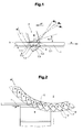
- FIG. 1 illustrates a single cutting step of a first, exemplary embodiment of the inventive method.
- the paper layers 1 to be severed are shown stationary, while the axis of rotation M of the cutting disk 2 moves in a direction F '.
- This corresponds to a promotion of the paper layers 1 in the direction F at a stationary axis of rotation M (synchronism of promotion F and disc rotation R).
- the cutting disc 2 Of the cutting disc 2, only the cutting edge 3 of a single cutting blade 4 is shown.
- the cutting edge 5 of the stationary counter knife 6 extends in the support plane of the paper layers 1 and perpendicular to the rotation axis M of the cutting wheel 2.
- the distance between the axis of rotation M of the cutting wheel 2 and the surface of the paper layers 1, and the cutting edge 5 of the counter knife 6 is such, that the cutting edge 3 of the cutting blade 2 arranged on the circumference of the cutting blade 2 can completely penetrate the paper layers 1. That is, a vertex of the cutting wheel 2 lying beyond the cutting edge 5 of the counter knife 6 has a distance from the cutting edge 5 which is greater than the radial distance between the two ends of the cutting edge 3.
- the cutting disc 2 and the counter blade 6 are relative to each other and the cutting blade 4 is arranged on the cutting disc 2 such that the cutting edges 3 in the direction of rotation R trailing and radially outer end of the cutting edge 3, the first striking the paper layers 1 cutting tip 7, wherein this cutting tip 7 dives into the paper layers 1 in a still uncut position and the cutting direction (direction of movement of the point of intersection K of the cutting edges of the cutting knife and counter knife) is rectified with the conveying direction F.
- the cutting edge 3 of the cutting blade 4 is shown in three successive phases, indicated by indices .1, .2 and .3.
- the cutting step begins, that is, the cutting tip 7.1 hits the paper layers 1.
- the cutting step is completed, that is, the entire cutting edge 3.3 is on the side of the counter blade 6 outside the paper layers 1.
- the second phase (Index .2) is approximately midway between the first and the third phase, wherein the cutting edge of the cutting blade 3.2 crosses the cutting edge 5 of the counter knife 6.
- the cutting angle alpha between the cutting edge 3 and the cutting edge 5 of the counter knife 6 during the cutting step is greater.
- the cutting angle (alpha.1) is advantageously already greater than 15 ° and is not greater than, for example, 60 ° during the cutting step.
- the rotational speed R compared to the conveying speed F must be so large that the second edge 8, which together with the cutting edge 3 at an angle of advantageously about 90 °, the cutting tip 7 is formed and is not designed as a cutting edge to none Timing of the cutting step has a position relative to the paper layers 1, which is located further upstream than the position of the first impact of the cutting tip. 7
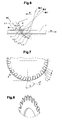
- FIG. 2 shows the device with viewing angle parallel to the cutting disc axis, FIG. 3 cut transversely to the conveying direction F.
- the mentioned, most important components are the cutting disc 2, on whose circumference the alternating cutting blades 4 and 4 'are arranged with cutting edges 3 and 3', two counter blades 6 and 6 'with cutting edges 5 and 5' and pressing means 10/11 and 10 '/ 11 '.
- the cutting edges 3 of the cutting blades 4 are in the plane of FIG FIG. 3 arranged on the left end face of the blade 2 and cooperate with the cutting edge 5 of counter blade 6.
- the cutting edges 3 ' are arranged in the plane of the right end of the blade 2 and cooperate with the cutting edge 5' of the counter blade 6 '.
- the counter knives 6 and 6 ' are advantageously arranged guided in a rail, such that they can be easily moved parallel to the conveying direction. With such a displacement, it becomes possible to replace a location of the cutting edge locally worn by the cutting steps with a not yet used or a less worn point, which extends the life of the counter knife relevant.
- the pressing means 10/11 and 10 '/ 11' the only in FIG. 3 are represented, the paper layers 1 press during the separation on both sides of the resulting parting line on each other and against the counter knives 6 and 6 ', such that the paper layers during the cutting steps fed to the cutting edges 5 and 5' are applied.
- the pressing means can also serve as conveying means with the aid of which the paper layers are conveyed through the separating point, or they can support further conveying means (not shown) in this conveying function.
- the pressing means are designed, for example, as pairs of counter-rotating around at least two rollers (not shown) rotating press belts 10 and 11, and 10 'and 11', wherein the press belt 10 or 10 'the separating wheel side and the press belt 11 or 11' on the counter-blade side is arranged and wherein the speed of the press belts corresponds to the conveying speed.
- the press belts of the pairs 10/11 and 10 '/ 11' or the rollers over which they run, are pressed against each other with suitable resilient means.
- at least one of the rollers is designed as actively driven drive rollers.
- FIGS. 4 and 5 show an exemplary embodiment of the blade 2 for the method according to FIG. 1 , This has at a diameter of only 200 mm, for example, 24 cutting blade 4 and alternately 24 cutting blade 4 ', the cutting edges 3 or 3' each between 5 and 15 mm, for example, about 10 mm long.
- the angle beta between the cutting edge 7 forming edges of the cutting blade is about 90 ° (between 85 ° and 95 °), the angle gamma between the tangent to the cutting tip 7 and the cutting edge 3 about 45 °.
- the direction of rotation R of the cutting disk 2 is such that the radially outer ends of the Trace the cutting edges behind the cutting edges.
- the position of the cutting edge 5 of the counter knife 6 is such that the radially outer ends of the cutting edges 3 meet first on the paper layers and therefore represent the cutting tips 7.
- the cutting disc 2 is for example in one piece, that is made of a solid disc, as in FIG. 5 is shown. But it can also be made of two mirror-image disk parts, wherein the disk parts are arranged relative to each other, that the cutting blades of one disk part are aligned with the gaps between the cutting blades of the other disk part (see below Fig. 10 +11). Two such part discs can be distanced from each other to produce wider joints by appropriate washers in a predetermined amount FIG. 5 is also clearly visible how the cutting edges 3 and 3 'of the cutting blades 4 and 4' are arranged alternately in the plane of one and the other end face of the cutting disc 2. The cutting edges of the cutting blade can be easily reground, but the cutting blades can also be designed self-sharpening
- FIGS. 6 to 8 show in the same representations as the FIGS. 1 . 4 and 5 a second, exemplary embodiment of method and apparatus according to the invention. Like elements are designated by like reference numerals.
- the main difference of this second embodiment from the first embodiment described in connection with the preceding figures is that the cutting tips 7, although in turn are the radially outer ends of the cutting edges 3, but precede the cutting edges. That is, the cutting tips 7 strike the paper layers in the end portion of the section of the preceding cutting step, and the cutting point K moves counter to the conveying direction F (cutting direction opposite to the conveying direction).
- the cutting angle alpha is smaller during the cutting step, but moves also here advantageously in a range below 60 ° and remains greater than 15 °.
- FIG. 9 shows very schematically a cutting step of a third, exemplary embodiment of the inventive method.
- the radially inner end (cutting tip 7) of the cutting edge 3 of the cutting blade 4 first strikes the paper layers 1 and is arranged in advance of the cutting edge 3. It results in a same cutting process as in FIG. 6 illustrated, ie with a cutting direction which is opposite to the conveying direction and with a decreasing during the cutting step cutting angle. From a comparison of Figures 9 and 6 shows that it is also possible to arrange the two ends of the cut edges 3 at the same radial distance from the blade axis, such that the cut edges 3 are perpendicular to a central radius.
- the method according to the invention can be used not only for separating paper layers but also for trimming such paper layers. Since, as mentioned above for such a trimming only on one side of the dividing line, a high edge quality is desired, a cutting disc can be used, at which the cutting edges of all cutting blades in the plane of the same disc face are (see below Fig. 13 ).
- Fig. 10-12 show two examples of a cutting disc 2, which is made of two mirror-image disc parts 12, 12 ', which with an angular offset ( Fig. 10 +11) or congruent ( Fig. 12 ) are mounted on each other.
- Fig. 11 Like the sectional view in Fig. 11 shows, the axially outwardly facing surfaces of the disc parts 12, 12 'substantially flat.
- the respective inwardly facing surfaces are structured to form the cutting blades 4, 4 '.
- the manufacturing technology are conditional, so that at the cutting edges 3, 3 'of the blades 4, 4' sharp cutting tips 7, 7 'can be formed.
- the angular offset is in the case of Fig. 10 such that in each case a notch 13, 13 'strikes a cutting blade 4, 4' of the counter-pane.
- Fig. 13 shows an example for producing a side section of the paper layers 1 with only one disc part 12, the according to 10 or 12 is trained. The paper layers are pressed when cutting from above and below.
Landscapes
- Life Sciences & Earth Sciences (AREA)
- Forests & Forestry (AREA)
- Engineering & Computer Science (AREA)
- Mechanical Engineering (AREA)
- Details Of Cutting Devices (AREA)
- Nonmetal Cutting Devices (AREA)
- Sheets, Magazines, And Separation Thereof (AREA)
- Perforating, Stamping-Out Or Severing By Means Other Than Cutting (AREA)
Priority Applications (1)
| Application Number | Priority Date | Filing Date | Title |
|---|---|---|---|
| EP20100010479 EP2266764B1 (fr) | 2007-07-11 | 2008-07-08 | Procédé et dispositif destinés à sectionner des couches de papiers transportées en continu |
Applications Claiming Priority (1)
| Application Number | Priority Date | Filing Date | Title |
|---|---|---|---|
| CH11162007 | 2007-07-11 |
Related Child Applications (2)
| Application Number | Title | Priority Date | Filing Date |
|---|---|---|---|
| EP20100010479 Division EP2266764B1 (fr) | 2007-07-11 | 2008-07-08 | Procédé et dispositif destinés à sectionner des couches de papiers transportées en continu |
| EP10010479.3 Division-Into | 2010-09-24 |
Publications (3)
| Publication Number | Publication Date |
|---|---|
| EP2014427A2 true EP2014427A2 (fr) | 2009-01-14 |
| EP2014427A3 EP2014427A3 (fr) | 2009-03-04 |
| EP2014427B1 EP2014427B1 (fr) | 2012-01-11 |
Family
ID=38698317
Family Applications (2)
| Application Number | Title | Priority Date | Filing Date |
|---|---|---|---|
| EP20100010479 Not-in-force EP2266764B1 (fr) | 2007-07-11 | 2008-07-08 | Procédé et dispositif destinés à sectionner des couches de papiers transportées en continu |
| EP20080405172 Not-in-force EP2014427B1 (fr) | 2007-07-11 | 2008-07-08 | Procédé et dispositif destinés à sectionner des couches de papiers transportées en continu |
Family Applications Before (1)
| Application Number | Title | Priority Date | Filing Date |
|---|---|---|---|
| EP20100010479 Not-in-force EP2266764B1 (fr) | 2007-07-11 | 2008-07-08 | Procédé et dispositif destinés à sectionner des couches de papiers transportées en continu |
Country Status (6)
| Country | Link |
|---|---|
| US (1) | US8069759B2 (fr) |
| EP (2) | EP2266764B1 (fr) |
| AT (1) | ATE540788T1 (fr) |
| AU (1) | AU2008203029B2 (fr) |
| CA (1) | CA2636961A1 (fr) |
| DK (1) | DK2014427T3 (fr) |
Families Citing this family (1)
| Publication number | Priority date | Publication date | Assignee | Title |
|---|---|---|---|---|
| CN109015780B (zh) * | 2018-08-10 | 2024-02-02 | 安徽格林开思茂光电科技股份有限公司 | 一种触摸屏切割刀具 |
Citations (2)
| Publication number | Priority date | Publication date | Assignee | Title |
|---|---|---|---|---|
| CH666651A5 (de) | 1984-01-20 | 1988-08-15 | Hagen Gaemmerler | Vorrichtung zum kontinuierlichen trennen von uebereinanderliegenden blattfoermigen gebilden. |
| WO2005102624A1 (fr) | 2004-04-26 | 2005-11-03 | Gramatec Gmbh | Lame destinee a des installations de coupe rotatives |
Family Cites Families (14)
| Publication number | Priority date | Publication date | Assignee | Title |
|---|---|---|---|---|
| US1473377A (en) * | 1923-11-06 | Machine for cutting | ||
| US3142216A (en) * | 1961-02-07 | 1964-07-28 | Carl F Rupnow | Slot cutting machine for continuously advancing strip material |
| FR2394326A1 (fr) * | 1977-06-16 | 1979-01-12 | Destructeurs Indls Exploit | Perfectionnements aux appareils pour la destruction de documents |
| DE3313103A1 (de) * | 1983-04-12 | 1984-10-18 | Feinwerktechnik Schleicher & Co, 7778 Markdorf | Schneideinrichtung fuer vorrichtungen zum zerkleinern von zerkleinerungsgut aus flachmaterial oder flachmateriallagen, wie dokumenten etc. |
| US4589458A (en) * | 1984-10-29 | 1986-05-20 | Vermont American Corporation | Multiple saw blade adjustable dado cutter |
| DE3536989A1 (de) * | 1985-10-17 | 1987-04-23 | Aichele Werkzeuge Gmbh & Co Kg | Messerscheibe, insbesondere zum beschneiden von papier |
| US4643060A (en) * | 1986-02-03 | 1987-02-17 | Westvaco Corporation | Air cooled slotter and slitter blade cutting edges |
| US4717328A (en) * | 1986-04-07 | 1988-01-05 | Alterio Joseph C D | Slitter-corrugator apparatus for pasta |
| US5309962A (en) * | 1993-05-13 | 1994-05-10 | Vermont American Corporation | Multiple saw blade adjustable dado cutter assembly including a cam assembly and nestable dado blades |
| EP0960006B1 (fr) * | 1997-01-30 | 2002-04-17 | Ferag AG | Procede et dispositif pour couper des objets plats achemines en continu |
| US6073527A (en) * | 1997-04-11 | 2000-06-13 | Marquip, Inc. | Method and apparatus for direct shingling of cut sheets at the cutoff knife |
| US5890409A (en) * | 1997-05-20 | 1999-04-06 | Zenith Cutter Co. | Slotting blade with out-of-phase serrations |
| US7044410B2 (en) * | 2003-11-26 | 2006-05-16 | Michilin Prosperity Co., Ltd. | Round undulating blade and blade module for shredder |
| DE202004004275U1 (de) * | 2004-03-17 | 2004-06-03 | Imabt Weichselbaum Inh. Bernhard Teufel E.K. | Messer für eine Schneidvorrichtung |
-
2008
- 2008-07-07 CA CA 2636961 patent/CA2636961A1/fr not_active Abandoned
- 2008-07-08 EP EP20100010479 patent/EP2266764B1/fr not_active Not-in-force
- 2008-07-08 EP EP20080405172 patent/EP2014427B1/fr not_active Not-in-force
- 2008-07-08 DK DK08405172T patent/DK2014427T3/da active
- 2008-07-08 AT AT08405172T patent/ATE540788T1/de active
- 2008-07-09 AU AU2008203029A patent/AU2008203029B2/en not_active Expired - Fee Related
- 2008-07-10 US US12/170,757 patent/US8069759B2/en not_active Expired - Fee Related
Patent Citations (2)
| Publication number | Priority date | Publication date | Assignee | Title |
|---|---|---|---|---|
| CH666651A5 (de) | 1984-01-20 | 1988-08-15 | Hagen Gaemmerler | Vorrichtung zum kontinuierlichen trennen von uebereinanderliegenden blattfoermigen gebilden. |
| WO2005102624A1 (fr) | 2004-04-26 | 2005-11-03 | Gramatec Gmbh | Lame destinee a des installations de coupe rotatives |
Also Published As
| Publication number | Publication date |
|---|---|
| US20090013841A1 (en) | 2009-01-15 |
| US8069759B2 (en) | 2011-12-06 |
| ATE540788T1 (de) | 2012-01-15 |
| EP2266764B1 (fr) | 2012-08-29 |
| CA2636961A1 (fr) | 2009-01-11 |
| EP2014427A3 (fr) | 2009-03-04 |
| AU2008203029B2 (en) | 2013-05-02 |
| DK2014427T3 (da) | 2012-04-16 |
| EP2014427B1 (fr) | 2012-01-11 |
| EP2266764A1 (fr) | 2010-12-29 |
| AU2008203029A1 (en) | 2009-01-29 |
Similar Documents
| Publication | Publication Date | Title |
|---|---|---|
| DE69601366T2 (de) | Verfahren sowie vorrichtung zum schneiden von teigprodukten | |
| DE69630243T2 (de) | Verfahren und vorrichtung zur herstellung von geschnittetem käse | |
| DE3878592T2 (de) | Schneidmesseraufbau fuer produkte, die durch druckwasser transportiert werden. | |
| DE3112639C2 (fr) | ||
| DE102007059625B4 (de) | Strangschneidvorrichtung | |
| DE3313103A1 (de) | Schneideinrichtung fuer vorrichtungen zum zerkleinern von zerkleinerungsgut aus flachmaterial oder flachmateriallagen, wie dokumenten etc. | |
| DE102012109003A1 (de) | Aufschnittschneidemaschine | |
| EP3680078B1 (fr) | Dispositif et procede de fabrication d'un fil pour l'industrie du tabac | |
| DD143734A5 (de) | Schneidsatz fuer eine vorrichtung zum zerkleinern von nahrungsmitteln | |
| DE2061703A1 (de) | Rollenschneidvornchtung | |
| EP2222156A1 (fr) | Découpe d'une masse de denrée alimentaire molle | |
| DE68908328T2 (de) | Würfelschneidvorrichtung. | |
| DE4214730C2 (de) | Kuttermesser | |
| DE102004046127A1 (de) | Wellpappe-Anlage und Verfahren zur Herstellung von Wellpappe-Bögen | |
| EP3459699B1 (fr) | Couteau | |
| EP2014427B1 (fr) | Procédé et dispositif destinés à sectionner des couches de papiers transportées en continu | |
| EP2279145B1 (fr) | Dispositif de pliage présentant des arbres d'outils de coupe ou analogues montés en amont ou en aval | |
| EP3430915A1 (fr) | Dispositif de coupe d'article en forme de tige et de machine dotée d'un tel dispositif | |
| DE102016005443A1 (de) | Schneidmesser, Vorrichtung zum Aufschneiden von Lebensmittelprodukten mit einem solchen Schneidmesser sowie Verwendung und Verfahren zur Herstellung eines Schneidmessers | |
| EP0255626B1 (fr) | Paire d'arbres équipés de lames pour le découpage de matériaux en bandes, spécialement du carton ondulé | |
| DE19924454B4 (de) | Vorrichtung zum Schneiden von Materialbahnen | |
| DE1907572A1 (de) | Verfahren und Vorrichtung zum Schneiden von Wellpappe | |
| DE2553539C2 (de) | Verfahren und Vorrichtung zum Zerteilen eines gebrauchten Luftreifens | |
| EP0993349B1 (fr) | Dispositif pour decouper des aretes longitudinales de bandes plates | |
| DE60204888T2 (de) | Rotierendes standwerkzeug zum kontinuierlischen lochen von profilen sowie verwendung desselben |
Legal Events
| Date | Code | Title | Description |
|---|---|---|---|
| PUAI | Public reference made under article 153(3) epc to a published international application that has entered the european phase |
Free format text: ORIGINAL CODE: 0009012 |
|
| AK | Designated contracting states |
Kind code of ref document: A2 Designated state(s): AT BE BG CH CY CZ DE DK EE ES FI FR GB GR HR HU IE IS IT LI LT LU LV MC MT NL NO PL PT RO SE SI SK TR |
|
| AX | Request for extension of the european patent |
Extension state: AL BA MK RS |
|
| PUAL | Search report despatched |
Free format text: ORIGINAL CODE: 0009013 |
|
| AK | Designated contracting states |
Kind code of ref document: A3 Designated state(s): AT BE BG CH CY CZ DE DK EE ES FI FR GB GR HR HU IE IS IT LI LT LU LV MC MT NL NO PL PT RO SE SI SK TR |
|
| AX | Request for extension of the european patent |
Extension state: AL BA MK RS |
|
| 17Q | First examination report despatched |
Effective date: 20091007 |
|
| 17P | Request for examination filed |
Effective date: 20090826 |
|
| AKX | Designation fees paid |
Designated state(s): AT BE BG CH CY CZ DE DK EE ES FI FR GB GR HR HU IE IS IT LI LT LU LV MC MT NL NO PL PT RO SE SI SK TR |
|
| GRAP | Despatch of communication of intention to grant a patent |
Free format text: ORIGINAL CODE: EPIDOSNIGR1 |
|
| GRAS | Grant fee paid |
Free format text: ORIGINAL CODE: EPIDOSNIGR3 |
|
| GRAA | (expected) grant |
Free format text: ORIGINAL CODE: 0009210 |
|
| AK | Designated contracting states |
Kind code of ref document: B1 Designated state(s): AT BE BG CH CY CZ DE DK EE ES FI FR GB GR HR HU IE IS IT LI LT LU LV MC MT NL NO PL PT RO SE SI SK TR |
|
| REG | Reference to a national code |
Ref country code: GB Ref legal event code: FG4D Free format text: NOT ENGLISH |
|
| REG | Reference to a national code |
Ref country code: CH Ref legal event code: EP |
|
| REG | Reference to a national code |
Ref country code: AT Ref legal event code: REF Ref document number: 540788 Country of ref document: AT Kind code of ref document: T Effective date: 20120115 |
|
| REG | Reference to a national code |
Ref country code: CH Ref legal event code: NV Representative=s name: FREI PATENTANWALTSBUERO AG |
|
| REG | Reference to a national code |
Ref country code: IE Ref legal event code: FG4D |
|
| REG | Reference to a national code |
Ref country code: DE Ref legal event code: R096 Ref document number: 502008006102 Country of ref document: DE Effective date: 20120315 |
|
| REG | Reference to a national code |
Ref country code: DK Ref legal event code: T3 |
|
| REG | Reference to a national code |
Ref country code: SE Ref legal event code: TRGR |
|
| REG | Reference to a national code |
Ref country code: NL Ref legal event code: VDEP Effective date: 20120111 |
|
| PG25 | Lapsed in a contracting state [announced via postgrant information from national office to epo] |
Ref country code: SI Free format text: LAPSE BECAUSE OF FAILURE TO SUBMIT A TRANSLATION OF THE DESCRIPTION OR TO PAY THE FEE WITHIN THE PRESCRIBED TIME-LIMIT Effective date: 20120111 |
|
| LTIE | Lt: invalidation of european patent or patent extension |
Effective date: 20120111 |
|
| PG25 | Lapsed in a contracting state [announced via postgrant information from national office to epo] |
Ref country code: HR Free format text: LAPSE BECAUSE OF FAILURE TO SUBMIT A TRANSLATION OF THE DESCRIPTION OR TO PAY THE FEE WITHIN THE PRESCRIBED TIME-LIMIT Effective date: 20120111 Ref country code: IS Free format text: LAPSE BECAUSE OF FAILURE TO SUBMIT A TRANSLATION OF THE DESCRIPTION OR TO PAY THE FEE WITHIN THE PRESCRIBED TIME-LIMIT Effective date: 20120511 Ref country code: LT Free format text: LAPSE BECAUSE OF FAILURE TO SUBMIT A TRANSLATION OF THE DESCRIPTION OR TO PAY THE FEE WITHIN THE PRESCRIBED TIME-LIMIT Effective date: 20120111 Ref country code: NL Free format text: LAPSE BECAUSE OF FAILURE TO SUBMIT A TRANSLATION OF THE DESCRIPTION OR TO PAY THE FEE WITHIN THE PRESCRIBED TIME-LIMIT Effective date: 20120111 Ref country code: NO Free format text: LAPSE BECAUSE OF FAILURE TO SUBMIT A TRANSLATION OF THE DESCRIPTION OR TO PAY THE FEE WITHIN THE PRESCRIBED TIME-LIMIT Effective date: 20120411 Ref country code: BG Free format text: LAPSE BECAUSE OF FAILURE TO SUBMIT A TRANSLATION OF THE DESCRIPTION OR TO PAY THE FEE WITHIN THE PRESCRIBED TIME-LIMIT Effective date: 20120411 |
|
| REG | Reference to a national code |
Ref country code: IE Ref legal event code: FD4D |
|
| PG25 | Lapsed in a contracting state [announced via postgrant information from national office to epo] |
Ref country code: FI Free format text: LAPSE BECAUSE OF FAILURE TO SUBMIT A TRANSLATION OF THE DESCRIPTION OR TO PAY THE FEE WITHIN THE PRESCRIBED TIME-LIMIT Effective date: 20120111 Ref country code: LV Free format text: LAPSE BECAUSE OF FAILURE TO SUBMIT A TRANSLATION OF THE DESCRIPTION OR TO PAY THE FEE WITHIN THE PRESCRIBED TIME-LIMIT Effective date: 20120111 Ref country code: PL Free format text: LAPSE BECAUSE OF FAILURE TO SUBMIT A TRANSLATION OF THE DESCRIPTION OR TO PAY THE FEE WITHIN THE PRESCRIBED TIME-LIMIT Effective date: 20120111 Ref country code: PT Free format text: LAPSE BECAUSE OF FAILURE TO SUBMIT A TRANSLATION OF THE DESCRIPTION OR TO PAY THE FEE WITHIN THE PRESCRIBED TIME-LIMIT Effective date: 20120511 Ref country code: GR Free format text: LAPSE BECAUSE OF FAILURE TO SUBMIT A TRANSLATION OF THE DESCRIPTION OR TO PAY THE FEE WITHIN THE PRESCRIBED TIME-LIMIT Effective date: 20120412 |
|
| PG25 | Lapsed in a contracting state [announced via postgrant information from national office to epo] |
Ref country code: CY Free format text: LAPSE BECAUSE OF FAILURE TO SUBMIT A TRANSLATION OF THE DESCRIPTION OR TO PAY THE FEE WITHIN THE PRESCRIBED TIME-LIMIT Effective date: 20120111 |
|
| PG25 | Lapsed in a contracting state [announced via postgrant information from national office to epo] |
Ref country code: RO Free format text: LAPSE BECAUSE OF FAILURE TO SUBMIT A TRANSLATION OF THE DESCRIPTION OR TO PAY THE FEE WITHIN THE PRESCRIBED TIME-LIMIT Effective date: 20120111 Ref country code: CZ Free format text: LAPSE BECAUSE OF FAILURE TO SUBMIT A TRANSLATION OF THE DESCRIPTION OR TO PAY THE FEE WITHIN THE PRESCRIBED TIME-LIMIT Effective date: 20120111 Ref country code: IE Free format text: LAPSE BECAUSE OF FAILURE TO SUBMIT A TRANSLATION OF THE DESCRIPTION OR TO PAY THE FEE WITHIN THE PRESCRIBED TIME-LIMIT Effective date: 20120111 Ref country code: EE Free format text: LAPSE BECAUSE OF FAILURE TO SUBMIT A TRANSLATION OF THE DESCRIPTION OR TO PAY THE FEE WITHIN THE PRESCRIBED TIME-LIMIT Effective date: 20120111 |
|
| PGFP | Annual fee paid to national office [announced via postgrant information from national office to epo] |
Ref country code: SE Payment date: 20120725 Year of fee payment: 5 |
|
| PLBE | No opposition filed within time limit |
Free format text: ORIGINAL CODE: 0009261 |
|
| STAA | Information on the status of an ep patent application or granted ep patent |
Free format text: STATUS: NO OPPOSITION FILED WITHIN TIME LIMIT |
|
| PG25 | Lapsed in a contracting state [announced via postgrant information from national office to epo] |
Ref country code: SK Free format text: LAPSE BECAUSE OF FAILURE TO SUBMIT A TRANSLATION OF THE DESCRIPTION OR TO PAY THE FEE WITHIN THE PRESCRIBED TIME-LIMIT Effective date: 20120111 |
|
| 26N | No opposition filed |
Effective date: 20121012 |
|
| PGFP | Annual fee paid to national office [announced via postgrant information from national office to epo] |
Ref country code: IT Payment date: 20120730 Year of fee payment: 5 |
|
| BERE | Be: lapsed |
Owner name: FERAG AG Effective date: 20120731 |
|
| REG | Reference to a national code |
Ref country code: DE Ref legal event code: R097 Ref document number: 502008006102 Country of ref document: DE Effective date: 20121012 |
|
| PG25 | Lapsed in a contracting state [announced via postgrant information from national office to epo] |
Ref country code: MC Free format text: LAPSE BECAUSE OF NON-PAYMENT OF DUE FEES Effective date: 20120731 |
|
| GBPC | Gb: european patent ceased through non-payment of renewal fee |
Effective date: 20120708 |
|
| REG | Reference to a national code |
Ref country code: FR Ref legal event code: ST Effective date: 20130329 |
|
| PG25 | Lapsed in a contracting state [announced via postgrant information from national office to epo] |
Ref country code: FR Free format text: LAPSE BECAUSE OF NON-PAYMENT OF DUE FEES Effective date: 20120731 Ref country code: GB Free format text: LAPSE BECAUSE OF NON-PAYMENT OF DUE FEES Effective date: 20120708 |
|
| PG25 | Lapsed in a contracting state [announced via postgrant information from national office to epo] |
Ref country code: BE Free format text: LAPSE BECAUSE OF NON-PAYMENT OF DUE FEES Effective date: 20120731 |
|
| PG25 | Lapsed in a contracting state [announced via postgrant information from national office to epo] |
Ref country code: MT Free format text: LAPSE BECAUSE OF FAILURE TO SUBMIT A TRANSLATION OF THE DESCRIPTION OR TO PAY THE FEE WITHIN THE PRESCRIBED TIME-LIMIT Effective date: 20120111 |
|
| PG25 | Lapsed in a contracting state [announced via postgrant information from national office to epo] |
Ref country code: ES Free format text: LAPSE BECAUSE OF FAILURE TO SUBMIT A TRANSLATION OF THE DESCRIPTION OR TO PAY THE FEE WITHIN THE PRESCRIBED TIME-LIMIT Effective date: 20120422 |
|
| REG | Reference to a national code |
Ref country code: DK Ref legal event code: EBP Effective date: 20130731 |
|
| REG | Reference to a national code |
Ref country code: SE Ref legal event code: EUG |
|
| PG25 | Lapsed in a contracting state [announced via postgrant information from national office to epo] |
Ref country code: SE Free format text: LAPSE BECAUSE OF NON-PAYMENT OF DUE FEES Effective date: 20130709 Ref country code: TR Free format text: LAPSE BECAUSE OF FAILURE TO SUBMIT A TRANSLATION OF THE DESCRIPTION OR TO PAY THE FEE WITHIN THE PRESCRIBED TIME-LIMIT Effective date: 20120111 |
|
| PG25 | Lapsed in a contracting state [announced via postgrant information from national office to epo] |
Ref country code: IT Free format text: LAPSE BECAUSE OF NON-PAYMENT OF DUE FEES Effective date: 20130708 Ref country code: LU Free format text: LAPSE BECAUSE OF NON-PAYMENT OF DUE FEES Effective date: 20120708 |
|
| PG25 | Lapsed in a contracting state [announced via postgrant information from national office to epo] |
Ref country code: HU Free format text: LAPSE BECAUSE OF FAILURE TO SUBMIT A TRANSLATION OF THE DESCRIPTION OR TO PAY THE FEE WITHIN THE PRESCRIBED TIME-LIMIT Effective date: 20080708 |
|
| REG | Reference to a national code |
Ref country code: AT Ref legal event code: MM01 Ref document number: 540788 Country of ref document: AT Kind code of ref document: T Effective date: 20130708 |
|
| PG25 | Lapsed in a contracting state [announced via postgrant information from national office to epo] |
Ref country code: DK Free format text: LAPSE BECAUSE OF NON-PAYMENT OF DUE FEES Effective date: 20130731 |
|
| PG25 | Lapsed in a contracting state [announced via postgrant information from national office to epo] |
Ref country code: AT Free format text: LAPSE BECAUSE OF NON-PAYMENT OF DUE FEES Effective date: 20130708 |
|
| PGFP | Annual fee paid to national office [announced via postgrant information from national office to epo] |
Ref country code: CH Payment date: 20160928 Year of fee payment: 9 Ref country code: DE Payment date: 20160722 Year of fee payment: 9 |
|
| REG | Reference to a national code |
Ref country code: DE Ref legal event code: R119 Ref document number: 502008006102 Country of ref document: DE |
|
| REG | Reference to a national code |
Ref country code: CH Ref legal event code: PL |
|
| PG25 | Lapsed in a contracting state [announced via postgrant information from national office to epo] |
Ref country code: LI Free format text: LAPSE BECAUSE OF NON-PAYMENT OF DUE FEES Effective date: 20170731 Ref country code: DE Free format text: LAPSE BECAUSE OF NON-PAYMENT OF DUE FEES Effective date: 20180201 Ref country code: CH Free format text: LAPSE BECAUSE OF NON-PAYMENT OF DUE FEES Effective date: 20170731 |