EP2014496B1 - Autosonnenblende und Führungsschienensystem - Google Patents
Autosonnenblende und Führungsschienensystem Download PDFInfo
- Publication number
- EP2014496B1 EP2014496B1 EP08010683A EP08010683A EP2014496B1 EP 2014496 B1 EP2014496 B1 EP 2014496B1 EP 08010683 A EP08010683 A EP 08010683A EP 08010683 A EP08010683 A EP 08010683A EP 2014496 B1 EP2014496 B1 EP 2014496B1
- Authority
- EP
- European Patent Office
- Prior art keywords
- guide
- sunshade
- pair
- sunshade panel
- panel
- Prior art date
- Legal status (The legal status is an assumption and is not a legal conclusion. Google has not performed a legal analysis and makes no representation as to the accuracy of the status listed.)
- Not-in-force
Links
Images



Classifications
-
- B—PERFORMING OPERATIONS; TRANSPORTING
- B60—VEHICLES IN GENERAL
- B60J—WINDOWS, WINDSCREENS, NON-FIXED ROOFS, DOORS, OR SIMILAR DEVICES FOR VEHICLES; REMOVABLE EXTERNAL PROTECTIVE COVERINGS SPECIALLY ADAPTED FOR VEHICLES
- B60J7/00—Non-fixed roofs; Roofs with movable panels, e.g. rotary sunroofs
- B60J7/0007—Non-fixed roofs; Roofs with movable panels, e.g. rotary sunroofs moveable head-liners, screens, curtains or blinds for ceilings
- B60J7/003—Non-fixed roofs; Roofs with movable panels, e.g. rotary sunroofs moveable head-liners, screens, curtains or blinds for ceilings one or more sliding rigid plate or lammellae
Definitions
- This document relates to an automotive sunshade panel and guide track system therefor and, more particularly, to an automotive sunshade panel and guide track system for use in conjunction with a sunroof.
- Automobiles are often provided with a sunroof that is fixed or positionable within a ceiling portion of a vehicle body to enhance passenger comfort.
- a rigid, glass or plastic panel is used to close-off the opening in the roof, as desired.
- a sunshade is typically provided that forms part of the headliner. The sunshade can be selectively closed to block off the opening to reduce or eliminate sunlight coming in through the sunroof panel.
- the lateral edges of the sunshade are provided with slide shoes that are slideably mounted within the guide tracks.
- a problem with this assembly design is that small dimensional variations in the slide shoes may yield large variations in the frictional force required to open and close the sunshade.
- U.S. Patent No. 3,691,686 proposes a window shade assembly including a curved shade frame and shroud in which a resilient shade having a curvature differing from that of the frame is installed.
- the shade has frictional means along the edges thereof to engage the frame and to enable restricted sliding motion therebetween.
- U.S. Patent No. 5,845,959 proposes a slide tilt roof apparatus wherein a rise/fall retaining portion is provided on a member which is longitudinally movable following the movement of the corresponding lifter so that the engagement portion at the rear end of the rising/falling link can be guided when the rising/falling link forwardly tilt pivots and also when the link pivots to erect, whereby the posture of the rising/falling link can be changed by a single member.
- a substantially flat sunshade is proposed as part of the apparatus, which is slideably positioned within a sunshade guide groove. The edges of the sunshade are provided with three tabs spaced along each edge and slideably mounted within the guide groove. Slide shoes are not used in the proposed design.
- U.S. Patent No. 6,729,074 proposes an assembly having two opposing parallel guides and a panel having two opposite parallel lateral edges said to cooperate with the guides for a frictional sliding movement of the panel relative to the guides.
- the edges of the panel are curved and provided with three tabs spaced along the edges, such that three contact points are provided between each edge and the corresponding guide.
- each contact point engages only one of the guide surfaces of the corresponding guide.
- two contact points are provided near the ends of each edge and there is also provided an intermediate contact point.
- the assembly is said to have utility in an open roof assembly for a vehicle.
- the sunshade assembly includes a frame, the frame having a pair of opposing guide tracks, each guide track having a pair of spaced parallel guide surfaces, a sunshade panel having a forward portion, a rearward portion and a pair of curved lateral edges, and a plurality of guide tabs extending outwardly from each of the pair of curved lateral edges and positioned along a radius of curvature for placement within the pair of opposing guide tracks, at least one of the guide tabs of each curved lateral edge positioned within the forward portion of the sunshade panel and at least one of the guide tabs of each curved lateral edge positioned within the rearward portion of the sunshade panel, wherein the at least one guide tab positioned within the forward portion of the sunshade panel and the at least one guide tab positioned within the rearward portion of the sunshade panel are each of a length sufficient to contact each parallel guide surface of the pair of spaced parallel guide surfaces to provide a friction
- a sunshade panel for use in an assembly having a pair of opposing guide tracks, each guide track having a pair of spaced parallel guide surfaces.
- the sunshade panel includes a forward portion, a rearward portion and a pair of curved lateral edges, and a plurality of guide tabs extending outwardly from each of the pair of curved lateral edges and positioned along a radius of curvature for placement within the pair of opposing guide tracks, at least one of the guide tabs of each curved lateral edge positioned within the forward portion of the sunshade panel and at least one of the guide tabs of each curved lateral edge positioned within the rearward portion of the sunshade panel, wherein the at least one guide tab positioned within the forward portion of the sunshade panel and the at least one guide tab positioned within the rearward portion of the sunshade panel are each of a length sufficient to contact each parallel guide surface of the pair of spaced parallel guide surfaces to provide a frictional slideable fit within the pair of opposing
- the plurality of guide tabs of each curved lateral edge includes a third guide tab positioned along a radius of curvature.
- the third guide tab may be positioned between the at least one guide tab positioned within the forward portion of the sunshade panel and the at least one guide tab positioned within the rearward portion of the sunshade panel.
- the third guide tab of the plurality of guide tabs of each curved lateral edge is of a thickness sufficient to contact each parallel guide surface of the pair of spaced parallel guide surfaces to provide a frictional slideable fit within the pair of opposing guide tracks. This provides a further enhancement in the frictional sliding movement of the sunshade panel relative to the guide tracks.
- relief cuts are provided within the at least one guide tab positioned within the forward portion of the sunshade panel and the at least one guide tab positioned within the rearward portion of the sunshade panel along portions of the curved lateral edge.
- sunshade panel only the respective edges of the sunshade panel are curved, although it is also contemplated that the sunshade panel is curved.
- the sunshade assemblies disclosed herein can be used in conjunction with a sunroof assembly for a vehicle having a roof opening defined in the fixed roof of the vehicle.
- a sunshade panel having a substrate manufactured from a glass-reinforced composite material with a foam layer covered on one side by a cloth.
- the sunshade panel is manufactured from a composite material such as glass-filled polypropylene.
- FIGS. 1-8 wherein like numerals are used to designate like elements throughout.
- FIG. 1 there is schematically shown a sunroof assembly 10 for a vehicle 12.
- a roof opening 14 is defined in a fixed roof 16 of vehicle 12 and a slide/tilt roof apparatus 18 for mounting on roof 16 of vehicle 12 is provided.
- Slide/tilt roof apparatus 18 is capable of changing the state of roof opening 14 from a closed state, to a vented state, to a fully opened state, through the use of panel 20.
- the slide/tilt roof apparatus 18 operates in a manner well-known known, with lifters 22 extending along in the direction of movement of the vehicle.
- the panel 20 may be formed of a transparent or colored glass or plastic, a metal plate or the like, and is fixedly attached with a metal frame (not shown) on a marginal portion of the inner face thereof and with a weather strip 24 on the outer periphery thereof.
- Lifters 22 projecting downward are mounted to each of the right and left sides of a frame 26.
- Frame 26 is secured below the roof 16 and is substantially U-shaped in plan having right and left side portions and a front portion.
- a connection plate 24 is secured to a longitudinally intermediate portion of the frame 26. The space enclosed by the connection plate 28 and the front portion of the frame 26 forms an inner opening portion 30.
- a drip rail 32 may also be provided, the opposite ends of which are connected to support members 34, respectively.
- Each of these support members 34 is longitudinally slidably supported by a shoe guide (not shown) and is operatively connected to the lifters 22, thereby permitting vertical movements of the lifters 22.
- a deflector 36 may also be provided that is capable of projecting upward from the opening portion 30 when the panel 20 is opened. Other details of the operation of sunroof assembly 10 may be found in U.S. Patent No. 5,845,959 .
- sunroof assembly 10 is provided with a sunshade assembly 40.
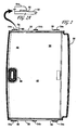
- the sunshade assembly includes frame 26, frame 26 having a pair of opposing guide tracks 42, each guide track 42 having a pair of spaced parallel guide surfaces 44.
- a sunshade panel 46 having a forward portion 48, a rearward portion 50 and a pair of curved lateral edges 52 is also provided.
- Sunshade panel 46 also includes a plurality of guide tabs 54(a-c) extending outwardly from each of the pair of curved lateral edges 52 and positioned along a radius of curvature R, for placement within the pair of opposing guide tracks 42.
- at least one of the guide tabs 54a of each curved lateral edge 52 may be positioned within the forward portion 48 of the sunshade panel 46 and at least one of the guide tabs 54c of each curved lateral edge 52 may be positioned within the rearward portion 50 of the sunshade panel 46.
- the at least one guide tab 54a, positioned within the forward portion 48 of the sunshade panel 46, and the at least one guide tab 54c, positioned within the rearward portion 50 of the sunshade panel 46 are each of a length sufficient to contact each parallel guide surface 44 of the pair of spaced parallel guide surfaces 44, to provide a frictional slideable fit within the pair of opposing guide tracks 42.
- a more stable frictional force is provided over the life of the vehicle when a driver of the vehicle manually positions sunshade panel 46 through the use of handle 56.
- the sunshade assemblies disclosed herein reduce the influence of dimensional variations on the resultant frictional forces.
- the plurality of guide tabs 54(a-c) of each curved lateral edge 52 includes a third guide tab 54b, which is positioned along radius of curvature R, as may be seen in FIGS. 3 and 4 .
- the third guide tab 54b is positioned between the at least one guide tab positioned within the forward portion of the sunshade panel 54a and the at least one guide tab positioned within the rearward portion of the sunshade panel 54c.
- the third guide tab 54b of the plurality of guide tabs of each curved lateral edge 52 is of a thickness sufficient to contact each parallel guide surface 44 of the pair of spaced parallel guide surfaces 44 to provide a frictional slideable fit within the pair of opposing guide tracks 42. This provides a further enhancement in the frictional sliding movement of the sunshade panel 46 relative to the guide tracks 42, when a driver of vehicle 12 manually engages a handle 56 of sunshade panel 46.
- the plurality of guide tabs 54(a-c) can be formed in any of several ways.
- the guide tabs 54(a-c) can comprise extensions of or projections from the respective curved lateral edges 52 of sunshade panel 46, attached thereto in any appropriate manner, or the guide tabs 54(a-c) may be the result of the provision of recesses in the respective curved lateral edges 52.
- relief cuts 60 are provided within the at least one guide tab 54a positioned within the forward portion 48 of the sunshade panel 46 and the at least one guide tab 54c positioned within the rearward portion 50 of the sunshade panel 46 along portions of the curved lateral edge 52.
- sunshade panel 46 may be seen to have a thickness which, at least in its edge region, is substantially similar to the thickness of the plurality of guide tabs 54(a-c). Further, as shown in FIGS. 1-3 , in addition to curved lateral edge 52, the sunshade panel itself 46 may be curved. In this form, the shape of the edge of the sunshade panel 46 and its inherent resiliency serve to enhance the frictional sliding movement of the sunshade panel 46 relative to the guide tracks 42.
- each opposing guide track 42 of frame 26 is substantially straight.
- roof designs vary from vehicle to vehicle.
- the pair of opposing guide tracks 42 may be substantially curved along a radius of curvature.
- the radius of curvature of the pair of opposing guide tracks 42 is greater than the radius of curvature of the plurality of guide tabs 54(a-c) of the pair of curved lateral edges 52.
- sunshade panel 46 is installed in a frame 26 in which opposing guide tracks 42 are substantially straight.
- sunshade panel 46 is curved in its entirety, it also envisioned and within the scope of this disclosure that sunshade panel 26 may be substantially flat. In this form, nevertheless, a pair of curved lateral edges 52 is provided together with a plurality of guide tabs 54(a-c) extending outwardly from each of the pair of curved lateral edges 52.
- the plurality of guide tabs 54(a-c) are positioned along a radius of curvature R for placement within the pair of opposing guide tracks 42, at least one of the guide tabs 54a of each curved lateral edge 52 positioned within the forward portion 48 of the sunshade panel 46 and at least one of the guide tabs 54c of each curved lateral edge 52 positioned within the rearward portion 50 of the sunshade panel 46.
- a panel substrate may be first manufactured from a suitable thermoplastic material.
- a foam layer (not shown) and a cloth layer (not shown) can be applied to the surface that will face the interior of the vehicle, as is conventional.
- Sunshade panel 46 may be produced by conventional thermoforming or compression molding, as desired.
- thermoplastic resins whether crystalline or amorphous, can be utilized.
- crystalline polymers include polyolefins, polyamides, polyesters, polyaryletherketones, polyoxy-methylene polymers, etc.
- amorphous polymers include polycarbonates, acrylics, polystyrenes, etc. Copolymers such as styrene-acrylonitriles and terpolymers such as acrylonitrile-styrene-acrylic and acrylonitrile-butadiene-styrene can also be used.
- alloys and blends of various thermoplastics described above can be used herein.
- Thermoplastic resins utilized herein should have good flow properties for ease of processing and structural integrity.
- the thermoplastic material may be reinforced with one or more reinforcing agents.
- Common reinforcing agents include fibrous materials such as glass fibers, polymeric fibers and natural fibers such as jute, and minerals such as mica and talc.
- One reinforcing agent having utility herein is glass fiber with a 10-20 micron diameter and a 3-4 mm length. Longer glass fibers of about 12 mm in length can also be used to further improve the properties of the thermoplastic material.
- the composite material is a high performance thermoplastic material such as glass-filled polypropylene.
- the composite material is a high performance thermoplastic material such as AZDEL ® , available from AZDEL, Inc. of Forest, Virginia. These materials come in two forms, AZDEL SuperLite ® , a low pressure, thermoformable composite of polypropylene and long chopped fiber combined with outer layers as needed. It is available as a sheet product that may be thermoformed into shape and is used in applications where a high stiffness-to-weight ratio is required. It is available in densities from 600 grams per square meter (gsm) to 2000 gsm.
- AZDEL Laminate ® GMT The other form is AZDEL Laminate ® GMT.
- AZDEL Laminate is a five layer composite of glass fiber and thermoplastic resin and is usually compression molded, although it may also be thermoformed using several industry standard methods of production.
- the sunshade panels and assemblies disclosed herein produce frictional forces and slide forces that do not vary significantly with varying dimensions. Moreover, variations in the shape of the sunshade panel or its edges do not have a large influence on the resulting frictional forces. Thus, an assembly is provided in which the sunshade panel experiences a rather consistent slide force, leading to reproducible results.
Landscapes
- Engineering & Computer Science (AREA)
- Mechanical Engineering (AREA)
- Window Of Vehicle (AREA)
- Vehicle Interior And Exterior Ornaments, Soundproofing, And Insulation (AREA)
- Seal Device For Vehicle (AREA)
Claims (8)
- Sonnenblendenanordnung mit:(a) einem Rahmen (26) mit einem Paar gegenüberliegender Führungsschienen (42, 42), wobei jede Führungsschiene (42, 42) ein Paar beabstandeter paralleler Führungsflächen (44, 44) hat,(b) einer Sonnenblendenplatte (46) mit einem vorderen Abschnitt (48), einem hinteren Abschnitt (50) und einem Paar gekrümmter Seitenränder (52, 52) und(c) mehreren Führungslaschen (54a, 54b, 54c), die sich von jedem des Paars gekrümmter Seitenränder (52, 52) nach außen erstrecken und entlang einem Krümmungsradius positioniert sind, um in dem Paar gegenüberliegender Führungsschienen (42, 42) platziert zu werden, wobei mindestens eine der Führungslaschen (54a, 54b, 54c) jedes gekrümmten Seitenrands im vorderen Abschnitt (48) der Sonnenblendenplatte (46) positioniert ist und mindestens eine der Führungslaschen (54a, 54c) jedes gekrümmten Seitenrands (52, 52) im hinteren Abschnitt (50) der Sonnenblendenplatte (46) positioniert ist,wobei die mindestens eine im vorderen Abschnitt (48) der Sonnenblendenplatte (46) positionierte Führungslasche (54a, 54c) und die mindestens eine im hinteren Abschnitt (50) der Sonnenblendenplatte (46) positionierte Führungslasche (54a, 54c) jeweils hinreichend lang sind, um jede parallele Führungsfläche (44, 44) des Paars beabstandeter paralleler Führungsflächen (44, 44) zu kontaktieren, um für eine gleitende Reibungspassung in dem Paar gegenüberliegender Führungsschienen (42, 42) zu sorgen, dadurch gekennzeichnet, dass die mehreren Führungslaschen (54a, 54c) jedes gekrümmten Seitenrands (52, 52) ferner eine dritte Führungslasche (54b) aufweisen, die entlang dem Krümmungsradius positioniert und zwischen der mindestens einen im vorderen Abschnitt (48) der Sonnenblendenplatte (46) positionierten Führungslasche (54a, 54c) und der mindestens einen im hinteren Abschnitt (50) der Sonnenblendenplatte (46) positionierten Führungslasche angeordnet ist, wobei die mindestens eine im vorderen Abschnitt (48) der Sonnenblendenplatte (46) positionierte Führungslasche (54a) und die mindestens eine im hinteren Abschnitt (50) der Sonnenblendenplatte (46) positionierte Führungslasche (54c) mit einer Freifräsung (60) entlang einem Abschnitt des gekrümmten Seitenrands (52, 52) versehen ist, wobei die Freifräsungen (60) Federung und Reibgleitbewegung der Sonnenblendenplatte (46) bezüglich der Führungsschienen (42, 42) verbessern.
- Sonnenblendenanordnung nach Anspruch 1, wobei die dritte Führungslasche (54b) der mehreren Führungslaschen (54a, 54b, 54c) jedes gekrümmten Seitenrands (52, 52) hinreichend dick ist, dass sie jede parallele Führungsfläche des Paars beabstandeter paralleler Führungsflächen (44, 44) kontaktiert.
- Sonnenblendenanordnung nach Anspruch 1 oder 2, wobei der hintere Abschnitt (50) der Sonnenblendenplatte (46) in einem sich nach oben erstreckenden Rand endet.
- Sonnenblendenanordnung nach einem der Ansprüche 1 bis 3, wobei jede des Paars gegenüberliegender Führungsschienen (42, 42) im Wesentlichen gerade ist.
- Sonnenblendenanordnung nach einem der Ansprüche 1 bis 4, wobei jede des Paars gegenüberliegender Führungsschienen (42, 42) im Wesentlichen entlang einem Krümmungsradius gekrümmt ist.
- Sonnenblendenanordnung nach Anspruch 5, wobei der Krümmungsradius jeder des Paars gegenüberliegender Führungsschienen (42, 42) größer als der Krümmungsradius der mehreren Führungslaschen (54a, 54b, 54c) jedes des Paars gekrümmter Seitenränder (52, 52) ist.
- Sonnenblendenanordnung nach einem der Ansprüche 1 bis 6, wobei die Sonnenblendenplatte (46) aus einem Material hergestellt ist, das ein thermoplastisches Harz umfasst, das aus Polyolefinen, Polyamiden, Polyestern, Polyaryletherketonen, Polyoxymethylenpolymeren und Copolymeren und Terpolymeren davon ausgewählt ist.
- Sonnenblendenanordnung nach einem der Ansprüche 1 bis 6, wobei die Sonnenblendenplatte (46) aus glasgefülltem Polypropylen hergestellt ist.
Applications Claiming Priority (1)
| Application Number | Priority Date | Filing Date | Title |
|---|---|---|---|
| US11/774,849 US20090015038A1 (en) | 2007-07-09 | 2007-07-09 | Automotive sunshade and guide track system therefor |
Publications (2)
| Publication Number | Publication Date |
|---|---|
| EP2014496A1 EP2014496A1 (de) | 2009-01-14 |
| EP2014496B1 true EP2014496B1 (de) | 2011-05-18 |
Family
ID=39639489
Family Applications (1)
| Application Number | Title | Priority Date | Filing Date |
|---|---|---|---|
| EP08010683A Not-in-force EP2014496B1 (de) | 2007-07-09 | 2008-06-12 | Autosonnenblende und Führungsschienensystem |
Country Status (3)
| Country | Link |
|---|---|
| US (1) | US20090015038A1 (de) |
| EP (1) | EP2014496B1 (de) |
| CN (1) | CN101342855B (de) |
Families Citing this family (4)
| Publication number | Priority date | Publication date | Assignee | Title |
|---|---|---|---|---|
| US7798548B2 (en) * | 2007-01-03 | 2010-09-21 | Gm Global Technology Operations, Inc. | Soft composite trim panel for a vehicle interior |
| US8052189B2 (en) * | 2009-12-01 | 2011-11-08 | Toyota Motor Engineering & Manufacturing North America, Inc. | Trim ring having reinforced snap posts |
| CN104742704B (zh) * | 2015-03-30 | 2017-02-01 | 安徽江淮汽车股份有限公司 | 一种汽车天窗总成 |
| DE102016100772A1 (de) * | 2016-01-19 | 2017-07-20 | Webasto SE | Anordnung für ein Fahrzeugdach, System und Verfahren zum Herstellen einer Anordnung für ein Fahrzeugdach |
Family Cites Families (9)
| Publication number | Priority date | Publication date | Assignee | Title |
|---|---|---|---|---|
| DE1157495B (de) * | 1962-03-01 | 1963-11-14 | Happich Gmbh Gebr | Schiebedach fuer Kraftfahrzeuge |
| US3691686A (en) * | 1971-03-30 | 1972-09-19 | Mc Donnell Douglas Corp | Window shade assembly |
| JPS6390431A (ja) * | 1986-10-01 | 1988-04-21 | Honda Motor Co Ltd | 車両のサンル−フ装置 |
| WO1996001192A1 (en) * | 1994-07-05 | 1996-01-18 | Asc Incorporated | Automobile sunroof assembly and control system |
| JP3505307B2 (ja) * | 1996-01-08 | 2004-03-08 | ベバスト ジャパン株式会社 | スライドチルトルーフ装置 |
| US6129413A (en) * | 1997-11-13 | 2000-10-10 | Asc Incorporated | Powered dual panel sunroof |
| DE10003377B4 (de) * | 2000-01-26 | 2004-12-23 | Webasto Vehicle Systems International Gmbh | Führungsanordnung für verstellbare Teile an Fahrzeugen |
| US6729074B1 (en) * | 2002-12-03 | 2004-05-04 | Inalfa Roof Systems Group B.V. | Assembly of guides and sliding panel, and sunshade for application therein |
| DE202004007359U1 (de) * | 2004-05-05 | 2004-08-12 | Webasto Ag | Schiebehimmelvorrichtung eines Fahrzeugdaches |
-
2007
- 2007-07-09 US US11/774,849 patent/US20090015038A1/en not_active Abandoned
-
2008
- 2008-06-12 EP EP08010683A patent/EP2014496B1/de not_active Not-in-force
- 2008-07-09 CN CN200810135693.XA patent/CN101342855B/zh not_active Expired - Fee Related
Also Published As
| Publication number | Publication date |
|---|---|
| CN101342855B (zh) | 2013-04-24 |
| CN101342855A (zh) | 2009-01-14 |
| EP2014496A1 (de) | 2009-01-14 |
| US20090015038A1 (en) | 2009-01-15 |
Similar Documents
| Publication | Publication Date | Title |
|---|---|---|
| US7997635B2 (en) | Bistable opening/closing device, and storage compartment comprising same | |
| EP0098050B1 (de) | Sonnenblendschutzvorrichtung | |
| US7581773B2 (en) | Roller blind with curved surface | |
| US8348313B2 (en) | Energy absorber for vehicle bumper | |
| US9227489B2 (en) | Side panel of a vehicle roof that can be opened | |
| US7287795B1 (en) | Vehicle storage structure | |
| EP2014496B1 (de) | Autosonnenblende und Führungsschienensystem | |
| CN101676144A (zh) | 带有聚合物垫子底座的交通工具座椅组件 | |
| EP1759960B1 (de) | Dachaufbau eines Fahrzeugs | |
| CN110171365B (zh) | 包括具有信息显示装置的可变形外表面的饰件 | |
| US5951091A (en) | Adjustable visor | |
| US7946648B2 (en) | Panel device for a sliding roof arrangement of a vehicle | |
| US4961608A (en) | Sun visor incorporating a slidable mirror | |
| WO1997035735A1 (en) | Tiltable full vision automobile windshield | |
| US20020190537A1 (en) | Visor assembly with extender blade | |
| US7922241B2 (en) | Sunshade with adjustable slide portion | |
| CN101875292A (zh) | 一种车用全景式天窗 | |
| EP2195181B1 (de) | Aus einem fahrzeugplattenmaterial hergestelltes visier | |
| US5609387A (en) | Lining panel for a sliding roof for a vehicle | |
| CN102858568B (zh) | 带有集成的卷帘的车辆顶盖 | |
| EP1698500B1 (de) | Sonnenblendenanordnung | |
| US5186512A (en) | Rear window sliding visor | |
| US8657357B2 (en) | Visor system for open-roof vehicles | |
| US11760173B2 (en) | Safari glass | |
| JPH0724270Y2 (ja) | 自動車のサンシェード支持装置 |
Legal Events
| Date | Code | Title | Description |
|---|---|---|---|
| PUAI | Public reference made under article 153(3) epc to a published international application that has entered the european phase |
Free format text: ORIGINAL CODE: 0009012 |
|
| AK | Designated contracting states |
Kind code of ref document: A1 Designated state(s): AT BE BG CH CY CZ DE DK EE ES FI FR GB GR HR HU IE IS IT LI LT LU LV MC MT NL NO PL PT RO SE SI SK TR |
|
| AX | Request for extension of the european patent |
Extension state: AL BA MK RS |
|
| 17P | Request for examination filed |
Effective date: 20090312 |
|
| 17Q | First examination report despatched |
Effective date: 20090428 |
|
| AKX | Designation fees paid |
Designated state(s): DE FR GB |
|
| GRAP | Despatch of communication of intention to grant a patent |
Free format text: ORIGINAL CODE: EPIDOSNIGR1 |
|
| GRAS | Grant fee paid |
Free format text: ORIGINAL CODE: EPIDOSNIGR3 |
|
| GRAA | (expected) grant |
Free format text: ORIGINAL CODE: 0009210 |
|
| REG | Reference to a national code |
Ref country code: GB Ref legal event code: FG4D |
|
| REG | Reference to a national code |
Ref country code: DE Ref legal event code: R096 Ref document number: 602008006964 Country of ref document: DE Effective date: 20110630 |
|
| PLBE | No opposition filed within time limit |
Free format text: ORIGINAL CODE: 0009261 |
|
| REG | Reference to a national code |
Ref country code: FR Ref legal event code: ST Effective date: 20120229 |
|
| STAA | Information on the status of an ep patent application or granted ep patent |
Free format text: STATUS: NO OPPOSITION FILED WITHIN TIME LIMIT |
|
| 26N | No opposition filed |
Effective date: 20120221 |
|
| PG25 | Lapsed in a contracting state [announced via postgrant information from national office to epo] |
Ref country code: FR Free format text: LAPSE BECAUSE OF NON-PAYMENT OF DUE FEES Effective date: 20110718 |
|
| REG | Reference to a national code |
Ref country code: DE Ref legal event code: R097 Ref document number: 602008006964 Country of ref document: DE Effective date: 20120221 |
|
| GBPC | Gb: european patent ceased through non-payment of renewal fee |
Effective date: 20120612 |
|
| PG25 | Lapsed in a contracting state [announced via postgrant information from national office to epo] |
Ref country code: GB Free format text: LAPSE BECAUSE OF NON-PAYMENT OF DUE FEES Effective date: 20120612 |
|
| PGFP | Annual fee paid to national office [announced via postgrant information from national office to epo] |
Ref country code: DE Payment date: 20190624 Year of fee payment: 12 |
|
| REG | Reference to a national code |
Ref country code: DE Ref legal event code: R119 Ref document number: 602008006964 Country of ref document: DE |
|
| PG25 | Lapsed in a contracting state [announced via postgrant information from national office to epo] |
Ref country code: DE Free format text: LAPSE BECAUSE OF NON-PAYMENT OF DUE FEES Effective date: 20210101 |