EP2014556A1 - Procédé et dispositif d'emballage continu de rouleaux de bande de matériau - Google Patents
Procédé et dispositif d'emballage continu de rouleaux de bande de matériau Download PDFInfo
- Publication number
- EP2014556A1 EP2014556A1 EP08159983A EP08159983A EP2014556A1 EP 2014556 A1 EP2014556 A1 EP 2014556A1 EP 08159983 A EP08159983 A EP 08159983A EP 08159983 A EP08159983 A EP 08159983A EP 2014556 A1 EP2014556 A1 EP 2014556A1
- Authority
- EP
- European Patent Office
- Prior art keywords
- wrapping
- web
- packaging material
- area
- web roll
- Prior art date
- Legal status (The legal status is an assumption and is not a legal conclusion. Google has not performed a legal analysis and makes no representation as to the accuracy of the status listed.)
- Withdrawn
Links
- 239000000463 material Substances 0.000 title claims abstract description 64
- 238000004806 packaging method and process Methods 0.000 title claims abstract description 30
- 238000000034 method Methods 0.000 title claims description 26
- 239000005022 packaging material Substances 0.000 claims description 82
- 238000004804 winding Methods 0.000 claims description 18
- 238000000926 separation method Methods 0.000 claims description 10
- 238000012545 processing Methods 0.000 claims description 6
- 239000006228 supernatant Substances 0.000 claims description 5
- 238000013519 translation Methods 0.000 claims description 5
- 238000011144 upstream manufacturing Methods 0.000 claims description 5
- 238000005253 cladding Methods 0.000 claims 2
- 239000000047 product Substances 0.000 claims 1
- 238000012856 packing Methods 0.000 abstract description 4
- 239000011111 cardboard Substances 0.000 abstract description 3
- 239000011087 paperboard Substances 0.000 abstract 1
- 238000013461 design Methods 0.000 description 5
- 239000000123 paper Substances 0.000 description 3
- 238000012546 transfer Methods 0.000 description 3
- 125000006850 spacer group Chemical group 0.000 description 2
- 241001589086 Bellapiscis medius Species 0.000 description 1
- 240000007839 Kleinhovia hospita Species 0.000 description 1
- 230000001154 acute effect Effects 0.000 description 1
- 150000001875 compounds Chemical class 0.000 description 1
- 238000011161 development Methods 0.000 description 1
- 238000006073 displacement reaction Methods 0.000 description 1
- 238000011143 downstream manufacturing Methods 0.000 description 1
- 238000005516 engineering process Methods 0.000 description 1
- 239000012530 fluid Substances 0.000 description 1
- 230000008595 infiltration Effects 0.000 description 1
- 238000001764 infiltration Methods 0.000 description 1
- 238000012858 packaging process Methods 0.000 description 1
- 239000000725 suspension Substances 0.000 description 1
Images


Classifications
-
- B—PERFORMING OPERATIONS; TRANSPORTING
- B65—CONVEYING; PACKING; STORING; HANDLING THIN OR FILAMENTARY MATERIAL
- B65G—TRANSPORT OR STORAGE DEVICES, e.g. CONVEYORS FOR LOADING OR TIPPING, SHOP CONVEYOR SYSTEMS OR PNEUMATIC TUBE CONVEYORS
- B65G13/00—Roller-ways
- B65G13/02—Roller-ways having driven rollers
-
- B—PERFORMING OPERATIONS; TRANSPORTING
- B65—CONVEYING; PACKING; STORING; HANDLING THIN OR FILAMENTARY MATERIAL
- B65B—MACHINES, APPARATUS OR DEVICES FOR, OR METHODS OF, PACKAGING ARTICLES OR MATERIALS; UNPACKING
- B65B11/00—Wrapping, e.g. partially or wholly enclosing, articles or quantities of material, in strips, sheets or blanks, of flexible material
- B65B11/008—Wrapping, e.g. partially or wholly enclosing, articles or quantities of material, in strips, sheets or blanks, of flexible material by webs revolving around articles moved along the axis of revolution
-
- B—PERFORMING OPERATIONS; TRANSPORTING
- B65—CONVEYING; PACKING; STORING; HANDLING THIN OR FILAMENTARY MATERIAL
- B65B—MACHINES, APPARATUS OR DEVICES FOR, OR METHODS OF, PACKAGING ARTICLES OR MATERIALS; UNPACKING
- B65B25/00—Packaging other articles presenting special problems
- B65B25/14—Packaging paper or like sheets, envelopes, or newspapers, in flat, folded, or rolled form
- B65B25/146—Packaging paper or like sheets, envelopes, or newspapers, in flat, folded, or rolled form packaging rolled-up articles
- B65B25/148—Jumbo paper rolls
-
- B—PERFORMING OPERATIONS; TRANSPORTING
- B65—CONVEYING; PACKING; STORING; HANDLING THIN OR FILAMENTARY MATERIAL
- B65G—TRANSPORT OR STORAGE DEVICES, e.g. CONVEYORS FOR LOADING OR TIPPING, SHOP CONVEYOR SYSTEMS OR PNEUMATIC TUBE CONVEYORS
- B65G15/00—Conveyors having endless load-conveying surfaces, i.e. belts and like continuous members, to which tractive effort is transmitted by means other than endless driving elements of similar configuration
- B65G15/10—Conveyors having endless load-conveying surfaces, i.e. belts and like continuous members, to which tractive effort is transmitted by means other than endless driving elements of similar configuration comprising two or more co-operating endless surfaces with parallel longitudinal axes, or a multiplicity of parallel elements, e.g. ropes defining an endless surface
-
- B—PERFORMING OPERATIONS; TRANSPORTING
- B65—CONVEYING; PACKING; STORING; HANDLING THIN OR FILAMENTARY MATERIAL
- B65G—TRANSPORT OR STORAGE DEVICES, e.g. CONVEYORS FOR LOADING OR TIPPING, SHOP CONVEYOR SYSTEMS OR PNEUMATIC TUBE CONVEYORS
- B65G47/00—Article or material-handling devices associated with conveyors; Methods employing such devices
- B65G47/22—Devices influencing the relative position or the attitude of articles during transit by conveyors
- B65G47/24—Devices influencing the relative position or the attitude of articles during transit by conveyors orientating the articles
- B65G47/248—Devices influencing the relative position or the attitude of articles during transit by conveyors orientating the articles by turning over or inverting them
-
- B—PERFORMING OPERATIONS; TRANSPORTING
- B65—CONVEYING; PACKING; STORING; HANDLING THIN OR FILAMENTARY MATERIAL
- B65G—TRANSPORT OR STORAGE DEVICES, e.g. CONVEYORS FOR LOADING OR TIPPING, SHOP CONVEYOR SYSTEMS OR PNEUMATIC TUBE CONVEYORS
- B65G2201/00—Indexing codes relating to handling devices, e.g. conveyors, characterised by the type of product or load being conveyed or handled
- B65G2201/02—Articles
- B65G2201/0232—Coils, bobbins, rolls
Definitions
- the invention relates to a method and an apparatus for the continuous packaging of web rolls in a packaging device.
- a packaging device comprising a wrapping station, in which the web roll is enveloped by means of a packaging material which is dispensed from a packaging material delivery device.
- a packaging material which is dispensed from a packaging material delivery device.
- different concepts are used, which differ essentially by the nature of the relative movement between the material web roll to be wrapped and the wrapping station, in particular the packaging material delivery device.
- the overall role is packaged in a single winding sequence, in which case an edge protection is also applied by supernatant of the packaging material on the front side of the web roll.
- Such wrapping devices are used in packaging systems, wherein after the targeted clocked wrapper wrapped with packaging material web roll can be subjected to further processing steps, such as the frontal application of Pappdeckelelementen.
- the individual stations are thereby cyclically successively through, wherein preferably the clock frequency is coordinated so that the processing operations in the individual clocks are characterized as possible by the same cycle time.
- An embodiment of a winding device for wrapping web rolls with stationary wrapping station, in particular packaging material delivery device is from the document EP 1 209 082 B1 previously known.
- the web of material to be wrapped is likewise supplied in a clock frequency to the wrapping station.
- This can be done for example by appropriate guidance on a rotatable drive roller or as a drive on the winding core.
- a roll of web material is wound in one cycle and then either fed or discharged to further processing units of the winding device.
- the known from the prior art solutions are characterized by a discontinuous operation, that is, for wrapping the roll or web roll, this is introduced into the wrapping station, wrapped and then re-executed before a new is introduced into the wrapping station.
- the appropriate packaging material strip is separated again and again with the next following bonded web roll.
- the invention is therefore based on the object to provide a method and an apparatus for the continuous wrapping web rolls. This solution should be characterized by the lowest possible design and control engineering effort.
- the method according to the invention for the continuous packaging of web rolls in a packaging device comprising at least one wrapping station, is characterized in that the individual web rolls are continuously supplied to the wrapping station at a constant distance from one another and guided therein by translational movement along a stationary packaging material delivery device with simultaneous rotational movement, wherein the packaging strip the individual web rolls in succession without interruption and over the distance between them wrapped and the so wrapped, run one behind the other by the wrapping web rolls via a separator to form a respective front projection between two adjacent and spaced web rolls separated at a distance between the web rolls By placing the continuous wrapper serving in this Ber is separated.
- the solution according to the invention thus makes it possible to feed a wrapping station continuously in succession with material web rolls and to wrap them around, the wrapping process continuing continuously without interruption becomes.
- the supernatant resulting from the separation in the distance region acts as edge protection.
- the coated web roll can then be further processed in a subsequent process section.
- the infeed and outfeed of the individual material web rolls takes place in a time-saving manner, thus parallel to the wrapping process of further material web rolls.
- the packaging material dispenser is stationary, i. in particular fixed in the feed direction of the material web rolls to be wrapped installed. Nevertheless, a pivoting, in particular for changing the angle of attack for the packaging strip relative to the surface of the web roll is possible.
- the stationary or at least during the wrapping process stationary remaining packaging material dispensing device is arranged according to a first embodiment with respect to the alignment of the longitudinal edge of the packaging material strip relative to the circumference of the termedee material web roll that this applied with its longitudinal edge in the circumferential direction of the web roll to the material web and superimposed by the feed movement Rotary motion is guided helically around the web roll. This design offers the advantage of a packaging material dispensing device with a small size and low design effort.
- the stationary or stationary during the wrapping process remaining packaging material dispensing device is aligned with respect to the longitudinal edge of the packaging material strip relative to the circumference of the passed web roll at an acute angle, so that this created with its longitudinal edge in the circumferential direction of the web roll to the web and through the rotational movement superimposed on the feed motion is guided around the web roll in a helical manner with a slight pitch.
- the winding circumference of a winding is extended.
- the packaging material strip is preferably passed around the web roll to increase the stability and strength of the package such that the windings of the packaging material wrapper overlap one another.
- the size of the overlap can be set differently.
- the proportion of the translational movement and / or the rotational movement of a web roll are freely adjustable. This makes it possible to pack different material web roll types, in particular with regard to the dimensioning of the width and / or diameter in a single packaging device without structural changes to each other solely by the vote of feed and rotational movement and also to meet different packaging requirements, in particular winding width, number of turns.
- the transport, the support function and the twisting movement take place via rotatably supported carrying rollers, wherein at least a part of these can be driven and the proportion of the translatory movement and / or the rotational movement of a web roll over the position of the longitudinal axes acting as axes of rotation the support rollers is preferably freely adjustable.
- the individual axes of rotation can be designed to be pivotable individually or in groups.
- pivotable and pivotable and drivable support rollers each to be arranged at a distance from each other, which is smaller than the minimum material web roll width.
- the individual support roller types are arranged in groups at a constant distance from each other in the enclosure area.
- the transfer between a feed region upstream of the wrapping region and / or a discharge region downstream of the wrapping region and the wrapping region can be effected by the force generating the translatory movement or the advancing movement in the direction of travel of the wrapping station, so that for these regions no additional drive unit is required.
- the speed of the translational movement of the roll of web material determining the feed rate in the wrapping region is kept constant. As a result, when these are used for transfer between the charging area and the wrapping area, a uniform distance between two web rolls fed one after another to the packaging device can be generated.
- the speed of the translatory movement of the material web roll determining the feed rate in the feed area and / or the discharge area is also kept constant, so that a constant throughput per unit time can be achieved in the entire packaging device.
- the material web roll is transported in the wrapping station by means of a corresponding transport device, via which both the translatory and rotational movement is produced on the material web roll.
- a corresponding transport device via which both the translatory and rotational movement is produced on the material web roll.
- the transport device used in the wrapping area is preferably also used across other functional areas.
- the inventive device for the continuous packaging of material web rolls comprises a wrapping station with at least one wrapping area with a stationary packaging material dispenser for continuous uninterrupted dispensing of a packaging material strip, a carrier for the web rolls, a transport device for guiding the web rolls along the packaging material dispenser, a drive device for rotating the web rolls around their Longitudinal axis and a separating device downstream of the wrapping area for separating the packaging material wrapping in the distance region between two web rolls wound one after the other.
- the carrying device and the drive device can be formed by at least one drivable carrying roller provided on the outer circumference or in the center of the web roll.
- the transport device is then provided as a separate device and essentially serves the feed. It is also conceivable to integrate the transport device and the carrying device in a structural unit and to provide a separate drive unit.
- the functions of the carrying device, the transport device and the drive device are taken over by at least one combined device.
- the individual drivable carrying rollers of a row are each arranged at a distance from one another which is smaller than the minimum width of a theoretically possible material web roll to be wrapped.
- the individual pivotable support rollers of a row are each arranged at a distance from each other, which is smaller than the minimum width of a web roll to be wrapped.
- the individual pivotable and / or drivable carrying rollers can be controlled individually or preferably in groups to reduce the control effort.
- the combined support and transport device can either be assigned to a separate drive means for generating the rotational movement of the material web rolls or at least at least a part of the support body in the form of balls or support rollers are driven such that these in cooperation with the individual Apply web roll to this one circumferential force.
- the corresponding support body are driven or rotated about an axis parallel to the feed direction.
- the separation of the packaging material wrapping takes place by utilizing the rotational movement of the web roll, in particular by hiring a separating element or a separating medium to the packaging material wrapping. This is the separator moved parallel and at the same speed relative to the feed direction of the web roll.
- FIG. 1 illustrates in schematic highly simplified representation of the basic principle and the basic structure of an inventively designed device 1 for the continuous packaging of web rolls 2.1 to 2.n, wherein the outer periphery 3 of the individual web rolls 2.1 to 2.n is wrapped with a packaging material 4.
- the wrapping of the web rolls 2.1 to 2.n, here exemplified the web rolls 2.1 and 2.2, with the Packaging material 4 takes place in a wrapping area II forming a wrapping station 5, which comprises a packaging material dispenser 6.
- the feeding of the wrapping station 5 takes place in a loading area I, which can be part of the wrapping station 5 or else is formed by a separate loading device 9, which is arranged upstream of the wrapping station 5.
- the discharge of the packaged material web rolls 2.1 to 2.n takes place in a discharge area III either directly from the wrapping station 5 or one of these downstream discharge station 24, wherein the Ausschleus Scheme III further processing stations not shown here, in particular devices 10 may be arranged downstream.
- the packaging material delivery device 6 is arranged stationary, that is, the position of this during the wrapping process is stationary.
- the packaging material dispensing device 6 dispenses a packaging material strip 4.1.
- the width b of the packaging material strip 4.1 is substantially smaller than the width b2 of a web roll 2.1 to 2.n, which is characterized by the extension of the individual web roll 2.1 to 2.n parallel to its longitudinal axis L 2.1 to L 2.n.
- the device 1 comprises a carrying device 23 for the material web rolls 2.n, a transport device 7 for transporting the material web rolls 2.1 to 2.n at least within the wrapping station 5 and a drive device 16 for rotating the web rolls 2.n about their longitudinal axes L 2.1 to L 2.n.
- the material web rolls 2.1 to 2.n are guided with their longitudinal axes L 2.1 to L 2.n along the packaging material dispensing device 6.
- the packaging material dispensing device 6 in particular the longitudinal axis of the carrying the packaging material roll support shaft parallel or at an angle to the longitudinal axes L 2.1 to L 2.n of the web rolls to be wrapped 2.1 to 2.n arranged.
- the transport device 7 simultaneously assumes the function of the carrying device 23 and the drive device 16 for the material web rolls 2.1 to 2.n.
- the web rolls 2.1 to 2.n are moved at least by the wrapping station 5, wherein the movement through the wrapping station 5 translationally, in particular laterally along themaschinesmaterialabgabevoriques 6 and the web rolls 2.1 to 2.n simultaneously a twisting about their longitudinal axes L 2.1 to L 2nd .n .
- the transport device 7, drive device 16 and carrying device 23 preferably extend at least over the wrapping region II, but preferably at least partially also into the loading region I and the discharge region III, so that an optimal transfer of the material web rolls takes place between the functional regions.
- the wrapping station 5 According to the feeding of the device 1 with the web rolls 2.1 to 2.n continuously by the web rolls 2.1 to 2.n successively free of interruptions while maintaining a predefined constant distance a to each other the wrapping station 5 are fed and then within the wrapping area II, preferably moved by the entire wrapping station 5 at a constant translation speed and are wrapped on the packaging material dispenser 6 with packaging material 4, wherein the wrapping over the distances a between two successively introduced into the wrapping station 5 web rolls 2.n and 2.n + 1 away to form a continuous packaging material web cover 14 takes place.
- the wrapping process is not interrupted, ie the packaging material strip 4.1 is discharged continuously.
- the individual material web rolls 2.n and 2.n + 1 are separated from one another at the exit from the wrapping station 5 in the region of the wrapped distance a via a separating device 8.
- the material enclosing the distance a remains as a supernatant 25.1 or 25.2, as detailed in the FIGS. 2a and 2 B shown, at the individual web rolls 2.1 to 2.n, wherein after discharge from the wrapping station 5 in a finishing station at each end of the web roll an inner end cover is applied and the protruding edge 25.1 and 25.2 is handled.
- an outer end cover is then arranged, which is preferably designed as a PE-coated cardboard / cardboard cover and under the influence of thermal energy is merged with the folded over supernatant or the non-concealed inner end cover.
- the charging device 9 is preferably provided. About this, which can be performed in different ways, the web rolls 2.1 to 2.n successively, that is offset in time and at a certain spatial distance a to each other the wrapping station 5 is supplied. The folding over of the edges 25.1, 25.2 can take place after discharge from the wrapping station 5 in a device 10 located downstream of the wrapping station 5.
- the individual material web roll 2.n is wrapped with a narrow packaging material strip 4.1.
- the wrapping operation is initiated by a circumferential force exerted on the packaging material roll 4 rotatably mounted in a packaging material dispenser 6.
- the packaging material strip 4.1 is applied at an angle to the longitudinal axis L 2.1 of the individual material web roll 2.1 on the circumference 3 of the web roll 2.1.
- the packaging material dispensing device 6 Since the packaging material dispensing device 6 is arranged stationarily, the wrapping of the material web roll 2.1 or 2.n over its extension in the longitudinal direction, that is parallel to the longitudinal axis L 2.n achieved by their translational movement with superimposed rotational movement. This is generated by the drive device 16 in the wrapping station 5, which is part of the device 1.
- the functions of the transport device and of the device for generating a rotational movement are combined in one device.
- a combined support, drive and transport device 26 is shown schematically in a greatly simplified representation in the FIGS. 2a and 2 B played.
- the number of packaging material windings around the circumference 3 of a web roll 2.n and their distance from each other and the degree of overlap by the transport speed of the web roll 2.n in wrapping II, the rotational speed of the web roll 2.n about its longitudinal axis, the diameter D of Web roll 2.n and the angle of attack of the packaging material dispenser 6 determined.
- the wrapping parameters for the packaging envelope of a material web roll 2.n can be set.
- FIG. 2a shows a schematic highly simplified representation of the guide here exemplified three web rolls 2.1, 2.2 and 2.3 by the device 1 in a view from above.
- the material web roll 2.1 has already the wrapping area II, which is described by the wrapping station 5, happened and is located in a subsequent to the wrapping area II discharge area III from the wrapping station 5. From the discharge area III can further transport to other processing units 10, such as a device for turning over the protruding edges 25.1, 25.2 and the application of a paper lid on both sides of the end faces of the individual web rolls 2.1 to 2.n and take place.
- processing units 10 such as a device for turning over the protruding edges 25.1, 25.2 and the application of a paper lid on both sides of the end faces of the individual web rolls 2.1 to 2.n and take place.
- These devices are devices that are known from the prior art in various designs and that can also be used here, which is why this will not be discussed in detail.
- the web roll 2.2 is already wrapped by means of the packaging material 4. It can also be seen that the material web roll 2.3 is still wrapped. It can be seen that the wrapping uninterrupted, that is free of interruptions and thus a closed packaging material shell 14 between the web roll 2.2 and the subsequent still present in the wrapping station 5 web roll 2.3 is present.
- the wrapped distance a between the material web rolls 2.1 and 2.2 has already passed the separating device 8, wherein the separating device 8 in the axial direction parallel to the translational movement of the web rolls 2.1 and 2.2 is movable and has become effective with a separating element 15 on the packaging material shell 14, in which case by the relative movement between the packaging material shell 14 and the separating element 15 due to the rotation of the web roll 2.2 a separation in the region of the distance a between two web rolls 2.1 and 2.2 is done.
- the separator 8 is to move to the completion of the separation process in the axial direction parallel to the longitudinal axis L 2.n of the respective web roll 2.n with.
- a separating element 15 act either a mechanical separator, such as a knife or alternative release means, such as laser or a fluid.
- the FIG. 2a illustrates a particularly advantageous combined support, drive and transport device 26, which meets the different requirements in the individual sections, loading area I, serving area II and Ausschleus Colour III and manages without a variety of different drive units.
- This therefore extends at least through the wrapping station 5, preferably at least partially into the loading device 9 and the discharge station 24.
- the combined carrying, drive and transport device 26 comprises two rows 12, 13 parallel arranged support elements, in particular support rollers 11.
- the rows are here with 12 and 13 designated.
- the support rollers 11 a row 12, 13 are arranged one behind the other in the transport direction. At least two such rows are provided, which are arranged parallel to each other. Conceivable are also embodiments in which even more rows can be provided.
- the rows 12 and 13 are aligned substantially parallel to the longitudinal axis L 2 of the material web roll 2 to be wrapped.
- the individual rows include support rollers 11 which are rotatably mounted about their longitudinal axes L 11.
- the individual rows 12 and 13 each contain at least one one, preferably a plurality of drivable support rollers 11.1 and more with its longitudinal axis L 11.2 relative to the longitudinal axis L 2 to be guided web roll 2 pivotable and rotatably mounted support rollers 11.2, wherein the drivable support rollers 11.1 also with its longitudinal axis L 11.2 relative to the longitudinal axis L 2 of to leading web roll 2 are pivotable.
- the width b of the packaging material strip and the transport speed through the wrapping station 5 is variable.
- the packaging process, in particular the wrapping process on the web roll 2 itself is varied with respect to the type of overlap width.
- the change in angle can also be used to feed the material web roll 2.n into and out of the device 1, in particular from the loading region I into the wrapping region II and the discharge region III.
- the individual support rollers 11, in particular the two rows 12 and 13, are stationary with respect to their position or position, but with respect to their longitudinal axes L 11 depending on the arrangement in the individual sections either rotatable or driven rotatably mounted.
- at least one or preferably a plurality of support rollers 11.2 arranged adjacent to each other or spaced apart from one another are provided, the longitudinal axes L 11.2 of which achieve the translational movement and thus the transport of the Web roll 2 by the wrapping station 5 perpendicular to the translation direction or feed direction or the longitudinal axis L 2 to be wrapped web roll 2.n are aligned.
- these rollers 11.2 in particular their engagement on the outer circumference 3, there is thus a displacement or a further transport of the individual material web roll 2 to be wrapped in the feed direction by the wrapping station 5.
- a plurality of support rollers 11.1 are preferably provided in the wrapping area II, which are drivable and further also pivotable. These are arranged in the rows 12, 13 spaced from one another, wherein the distance between two ⁇ the minimum width of a web roll to be wrapped must be 2.n. This statement applies analogously also to the only pivotable idlers 11.2.
- the pivoting of individual support rollers 11.1, 11.2 in the individual rows 12 and 13 can be done individually. Preferably, however, this is done in groups. For a particular type of web roll 2.n to be wrapped, the adjustment can be maintained. The effort keeps up therefore, with respect to the pivotability and the setting of the optimal transport conditions for the web roll 2.n by the wrapping station 5 in limits. Only when changing the material web roll parameters, in particular the material web roll type, for example by changing the diameter D and the length or width b2 and the type of winding and / or the desired packaging material is here to make a setting, the setting before the feed with the first web roll 2.1 Once done and for the remaining to be packaged web rolls 2.n + 1 is maintained. Since the support rollers, whether acting as drive rollers 11.1 or pure support rollers 11.2, are exposed to high loads, these have a cambered shape to reduce wear.
- the support rollers which are rotatable or tiltable with their longitudinal axis L 11.2 relative to the translatory movement direction, are provided only in the wrapping region II.
- the carrying rollers 11 are aligned with their longitudinal axes L 11 preferably perpendicular to the direction of translation.
- the rotational speed of the drivable carrying rollers 11.1 in the wrapping area II and in the area of the infeed and outfeed I, III can be different in and out of the packaging machine.
- the translational speed over all areas, that is, the infiltration I, in the wrapping area II and the discharge area III is kept constant.
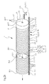
- FIG. 2b illustrates here a perspective view according to A in FIG. 2a , Visible here is the packaging strip 4.1 of the packaging material, the Material web roll 2.3 and the material web roll 2.2 enveloped together with the latter, the separating device 8 and the material web roll already separated and located in the region of the discharge III. It can also be seen that, after the separation process has taken place, the wrapping of the material web roll 2.1 projects past the end face thereof and can thus be taken in a downstream process.
- the packaging web 4 is applied with its longitudinal edge in the circumferential direction of the web roll 2 to this and due to the translational and this superimposed rotational movement of the web roll 2 helically guided around this.
- the dispenser 6 is in its position in the feed direction of the individual material web roll 2.n considered stationary, i. arranged stationary, so that the web roll is guided past this, in particular for changing the angle of attack of the packaging strip, however, this can be pivoted at an angle about a vertical to the feed direction, i. relative to the conveying direction of the web roll 2 determining direction or axis are changed in position, this position is then maintained during the wrapping process ..
- FIG. 3b Such a possibility is, for example, in a schematic simplified representation in the FIG. 3b played. Visible here is the storage or attachment of the packaging material delivery device 6 to a stationary frame or storage of this with a pivoting of the bearing axis at an angle ⁇ relative to the surface or the outer periphery 3 of the web roll to wrap 2.n creating an angle ⁇ between the longitudinal edge of the packaging material strip 4.1 and the circumferential direction of the web roll 2.n.
- FIG. 3a an embodiment with alignment of the longitudinal edge of the packaging material strip 4.1 in the circumferential direction of the web roll 2.n.
- the embodiment according to the solution according to the invention preferably further comprises a control device 20, according to the desired type of packaging and speed, in particular conveying speed and thus distance between the individual material web rolls to be packaged 2.n and 2.n + 1, the individual support rollers 11 with regard to the applied drive power and / or their position in relation to the direction of
- the individual support rollers 11 associated with adjusting devices, preferably in each case at least one adjusting device 21 for the influenceability of the drive power;
- a further adjusting device 22 for changing the position of the rotatably mounted support rollers 11.1, 11.2.
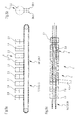
- FIGS. 4 and 5 illustrate an alternative embodiment of a support and transport device, preferably with integrated, but not shown here in detail drive device 16th
- FIG. 4a illustrates in schematic highly simplified representation of an embodiment of a combined device which at least the function of the support means 23 and transport means 7, and preferably also the drive means 16 takes over, in a view from below.
- This preferably comprises at least two mutually parallel ball chains 27.1, 27.2.
- ball chain 27.1, 27.2 When using the ball chain 27.1, 27.2 the principle of ball bushing is used.
- Such ball chains are already known in a variety of embodiments of the prior art, which is why the structure in detail will not be discussed further.
- These include a plurality of balls disposed adjacent each other by spacers to form an endless chain. Through the chain, usually lateral guidance, the individual balls are controlled separately.
- the ball chain 27.1, 27.2 extends parallel in the feed direction for the material web roll to be wrapped 2.n or 2.n + 1 and forms on the spherical surface punctiform contact areas at which the web roll is iststütz.
- the drive of the ball chain 27.1, 27.2 for translational movement takes place in the simplest case via a drivable guide and deflecting element in the form of a drive roller.
- the rotational movement of the material web rolls 2.1 to 2.n can by the drive at least one, preferably a plurality of Balls of the ball chain 27.1, 27.2 for rotation about an axis which is parallel to the feed direction can be realized.
- FIG. 4b illustrates an embodiment according to FIG. 4a in perspective view
- FIGS. 5a and 5b illustrate an alternative embodiment of a combined support, drive and transport 26 to FIG. 4 comprising at least two support roller belts 28.1, 28.2 with cylindrical elements in the form of support rollers in two views, which combine the function of the support means 23, the transport means 7 and the drive means 16 in one device.
- FIGS. 5a and 5b was dispensed with the presentation of the packaging material strip 4.1 and the wrapping of the web rolls 2.1 to 2.9.
- the basic principle is the same as that of a ball chain.
- the idlers are performed in a compound parallel to their center axes.
- this version is contrary to FIG. 4 characterized by line load, which excludes marks on the web roll largely.
- at least two parallel roller conveyor chains 28.2, 28.2 are provided.
- FIG. 5c illustrates a view from above of the wrapping station 5 according to FIG. 4 with representation of the packaging material strip 4.1.
Landscapes
- Engineering & Computer Science (AREA)
- Mechanical Engineering (AREA)
- Packaging Of Special Articles (AREA)
- Basic Packing Technique (AREA)
Applications Claiming Priority (1)
| Application Number | Priority Date | Filing Date | Title |
|---|---|---|---|
| DE200710032099 DE102007032099A1 (de) | 2007-07-10 | 2007-07-10 | Verfahren und Vorrichtung zum kontinuierlichen Verpacken von Materialbahnrollen |
Publications (1)
| Publication Number | Publication Date |
|---|---|
| EP2014556A1 true EP2014556A1 (fr) | 2009-01-14 |
Family
ID=39807815
Family Applications (1)
| Application Number | Title | Priority Date | Filing Date |
|---|---|---|---|
| EP08159983A Withdrawn EP2014556A1 (fr) | 2007-07-10 | 2008-07-09 | Procédé et dispositif d'emballage continu de rouleaux de bande de matériau |
Country Status (2)
| Country | Link |
|---|---|
| EP (1) | EP2014556A1 (fr) |
| DE (1) | DE102007032099A1 (fr) |
Cited By (5)
| Publication number | Priority date | Publication date | Assignee | Title |
|---|---|---|---|---|
| CN104494963A (zh) * | 2014-12-19 | 2015-04-08 | 无锡市士民机械设备厂 | 成圈包膜一体机的移盘装置 |
| CN104495500A (zh) * | 2014-12-19 | 2015-04-08 | 无锡市士民机械设备厂 | 成圈包膜一体机的钢丝绳推盘机构 |
| CN111392158A (zh) * | 2020-03-31 | 2020-07-10 | 福建佰达科技有限公司 | 一种基于智能控制的一体化无纺布包装码垛系统 |
| CN113834457A (zh) * | 2021-11-26 | 2021-12-24 | 天津赛象科技股份有限公司 | 包布宽度测量方法以及钢丝圈包布缠绕方法 |
| CN114701687A (zh) * | 2022-05-24 | 2022-07-05 | 滁州兴阳机械制造有限公司 | 一种棒材生产用统一打包运输装置 |
Families Citing this family (1)
| Publication number | Priority date | Publication date | Assignee | Title |
|---|---|---|---|---|
| CN109606814A (zh) * | 2019-01-23 | 2019-04-12 | 瑞通包装工业(河源)有限公司 | 一种自动化胶卷包装生产线 |
Citations (3)
| Publication number | Priority date | Publication date | Assignee | Title |
|---|---|---|---|---|
| FR1055390A (fr) * | 1952-05-03 | 1954-02-18 | Papeteries De La Chapelle | Procédé et dispositif d'emballage |
| DE19837981A1 (de) * | 1998-08-21 | 2000-02-24 | Voith Sulzer Papiertech Patent | Verfahren und Vorrichtung zum Verpacken von Materialbahnrollen |
| EP1209082A2 (fr) * | 2000-08-29 | 2002-05-29 | Saimatec Engineering Oy | Procédé et dispositif pour emballer des rouleaux de bande de papier et emballage de rouleau |
-
2007
- 2007-07-10 DE DE200710032099 patent/DE102007032099A1/de not_active Withdrawn
-
2008
- 2008-07-09 EP EP08159983A patent/EP2014556A1/fr not_active Withdrawn
Patent Citations (4)
| Publication number | Priority date | Publication date | Assignee | Title |
|---|---|---|---|---|
| FR1055390A (fr) * | 1952-05-03 | 1954-02-18 | Papeteries De La Chapelle | Procédé et dispositif d'emballage |
| DE19837981A1 (de) * | 1998-08-21 | 2000-02-24 | Voith Sulzer Papiertech Patent | Verfahren und Vorrichtung zum Verpacken von Materialbahnrollen |
| EP1209082A2 (fr) * | 2000-08-29 | 2002-05-29 | Saimatec Engineering Oy | Procédé et dispositif pour emballer des rouleaux de bande de papier et emballage de rouleau |
| EP1209082B1 (fr) | 2000-08-29 | 2006-11-29 | Saimatec Engineering Oy | Procédé et dispositif pour emballer des rouleaux de bande de papier et emballage de rouleau |
Cited By (7)
| Publication number | Priority date | Publication date | Assignee | Title |
|---|---|---|---|---|
| CN104494963A (zh) * | 2014-12-19 | 2015-04-08 | 无锡市士民机械设备厂 | 成圈包膜一体机的移盘装置 |
| CN104495500A (zh) * | 2014-12-19 | 2015-04-08 | 无锡市士民机械设备厂 | 成圈包膜一体机的钢丝绳推盘机构 |
| CN111392158A (zh) * | 2020-03-31 | 2020-07-10 | 福建佰达科技有限公司 | 一种基于智能控制的一体化无纺布包装码垛系统 |
| CN113834457A (zh) * | 2021-11-26 | 2021-12-24 | 天津赛象科技股份有限公司 | 包布宽度测量方法以及钢丝圈包布缠绕方法 |
| CN113834457B (zh) * | 2021-11-26 | 2022-02-22 | 天津赛象科技股份有限公司 | 包布宽度测量方法以及钢丝圈包布缠绕方法 |
| CN114701687A (zh) * | 2022-05-24 | 2022-07-05 | 滁州兴阳机械制造有限公司 | 一种棒材生产用统一打包运输装置 |
| CN114701687B (zh) * | 2022-05-24 | 2023-11-14 | 滁州兴阳机械制造有限公司 | 一种棒材生产用统一打包运输装置 |
Also Published As
| Publication number | Publication date |
|---|---|
| DE102007032099A1 (de) | 2009-01-15 |
Similar Documents
| Publication | Publication Date | Title |
|---|---|---|
| DE3119657C2 (de) | Verfahren und Maschine zur Herstellung von Verpackungseinheiten | |
| DE69421528T2 (de) | Umwickler mit Kontaktantrieb und Verfahren zur Minimalisierung des Schlupfes zwischen Antriebsrolle und Bahn | |
| DE69405151T2 (de) | Gerät zum Schneiden einer Materialbahn auf bestimmte Länge und zum Ausgeben derselben | |
| DE60311778T2 (de) | Zurückziehbare übergabeeinrichtung für eine dosiervorrichtung | |
| EP0765809B1 (fr) | Procédé pour emballer un rouleau d'une bande de matériau | |
| EP0176789A2 (fr) | Procédé et dispositif de changement des bobines relatif aux machines d'emballage | |
| EP2014556A1 (fr) | Procédé et dispositif d'emballage continu de rouleaux de bande de matériau | |
| EP3440946B1 (fr) | Machine de l'industrie de traitement du tabac destinée à la production simultanée d'une pluralité de boudins | |
| EP0304736B1 (fr) | Procédé et dispositif pour envelopper spécialement des paquets de cigarettes | |
| EP1751005B1 (fr) | Procede et dispositif d'emballage d'objets plats | |
| EP1013183B1 (fr) | Appareil pour enrober une bande autour des articles en forme de tige | |
| EP3885274A2 (fr) | Machine d'emballage et procédé d'emballage d'un produit à emballer avec un emballage extérieur produit à partir d'une bande supérieure de papier et d'une bande inférieure de papier | |
| EP3885275A2 (fr) | Dispositif de soudage et de coupure longitudinale pour une machine d'emballage et procédé d'emballage d'un produit à emballer avec un emballage extérieur produit à partir d'une bande supérieure de papier et d'une bande inférieure de papier | |
| DE102019116263B4 (de) | Einrichtung mit einer Mehrfach-Strangbildungsvorrichtung und Verfahren der Tabak verarbeitenden Industrie | |
| DE19857576A9 (de) | Vorrichtung zum Herumwickeln von Blättchen um stabförmige Gegenstände | |
| EP0982228B1 (fr) | Procédé et dispositif pour emballer des rouleaux de matériau en bande | |
| EP0384147B1 (fr) | Procédé et appareil pour l'emmagasinage intermédiaire de produits d'imprimerie pliés, à plusieurs feuilles, comme journaux, magazines et parties de ceux-ci | |
| DE1632190C3 (de) | Vorrichtung zum spiralförmigen Bewegen von längs aneinandergereihten Zigarrenwickeln | |
| DE19515440A1 (de) | Falzapparat | |
| EP0208244B1 (fr) | Dispositif pour rogner des produits imprimés délivrés en chevauchement | |
| EP1791775A1 (fr) | Dispositif d'enroulement sans interruption d'une bande textile acheminee en continu | |
| EP0873940B1 (fr) | Machine de coupe de rouleaux avec dispositif d'emballage | |
| EP1308100A2 (fr) | Dispositif de stockage en continu pour une matière en bande | |
| DE102017105298B4 (de) | Konfektionierungsanlage | |
| EP0695687B1 (fr) | Dispositif pour cercler des marchandises emballées |
Legal Events
| Date | Code | Title | Description |
|---|---|---|---|
| PUAI | Public reference made under article 153(3) epc to a published international application that has entered the european phase |
Free format text: ORIGINAL CODE: 0009012 |
|
| AK | Designated contracting states |
Kind code of ref document: A1 Designated state(s): AT BE BG CH CY CZ DE DK EE ES FI FR GB GR HR HU IE IS IT LI LT LU LV MC MT NL NO PL PT RO SE SI SK TR |
|
| AX | Request for extension of the european patent |
Extension state: AL BA MK RS |
|
| 17P | Request for examination filed |
Effective date: 20090714 |
|
| 17Q | First examination report despatched |
Effective date: 20090806 |
|
| AKX | Designation fees paid |
Designated state(s): AT DE FI IT SE |
|
| GRAP | Despatch of communication of intention to grant a patent |
Free format text: ORIGINAL CODE: EPIDOSNIGR1 |
|
| RIC1 | Information provided on ipc code assigned before grant |
Ipc: B65B 11/04 20060101ALI20120523BHEP Ipc: B65G 13/02 20060101ALI20120523BHEP Ipc: B65G 47/248 20060101AFI20120523BHEP Ipc: B65G 15/10 20060101ALI20120523BHEP Ipc: B65B 25/14 20060101ALI20120523BHEP Ipc: B65B 61/06 20060101ALI20120523BHEP |
|
| STAA | Information on the status of an ep patent application or granted ep patent |
Free format text: STATUS: THE APPLICATION IS DEEMED TO BE WITHDRAWN |
|
| 18D | Application deemed to be withdrawn |
Effective date: 20121023 |