EP2014840B1 - Ablaufgarnitur für Duschen oder Badewannen - Google Patents
Ablaufgarnitur für Duschen oder Badewannen Download PDFInfo
- Publication number
- EP2014840B1 EP2014840B1 EP08103885.3A EP08103885A EP2014840B1 EP 2014840 B1 EP2014840 B1 EP 2014840B1 EP 08103885 A EP08103885 A EP 08103885A EP 2014840 B1 EP2014840 B1 EP 2014840B1
- Authority
- EP
- European Patent Office
- Prior art keywords
- drain
- pipe
- connecting pieces
- section
- drain body
- Prior art date
- Legal status (The legal status is an assumption and is not a legal conclusion. Google has not performed a legal analysis and makes no representation as to the accuracy of the status listed.)
- Active
Links
Images
Classifications
-
- E—FIXED CONSTRUCTIONS
- E03—WATER SUPPLY; SEWERAGE
- E03F—SEWERS; CESSPOOLS
- E03F5/00—Sewerage structures
- E03F5/04—Gullies inlets, road sinks, floor drains with or without odour seals or sediment traps
- E03F5/0407—Floor drains for indoor use
- E03F5/0408—Floor drains for indoor use specially adapted for showers
-
- E—FIXED CONSTRUCTIONS
- E03—WATER SUPPLY; SEWERAGE
- E03C—DOMESTIC PLUMBING INSTALLATIONS FOR FRESH WATER OR WASTE WATER; SINKS
- E03C1/00—Domestic plumbing installations for fresh water or waste water; Sinks
- E03C1/12—Plumbing installations for waste water; Basins or fountains connected thereto; Sinks
- E03C1/20—Connecting baths or bidets to the wastepipe
-
- E—FIXED CONSTRUCTIONS
- E03—WATER SUPPLY; SEWERAGE
- E03C—DOMESTIC PLUMBING INSTALLATIONS FOR FRESH WATER OR WASTE WATER; SINKS
- E03C1/00—Domestic plumbing installations for fresh water or waste water; Sinks
- E03C1/12—Plumbing installations for waste water; Basins or fountains connected thereto; Sinks
- E03C1/22—Outlet devices mounted in basins, baths, or sinks
-
- E—FIXED CONSTRUCTIONS
- E03—WATER SUPPLY; SEWERAGE
- E03F—SEWERS; CESSPOOLS
- E03F5/00—Sewerage structures
- E03F5/04—Gullies inlets, road sinks, floor drains with or without odour seals or sediment traps
- E03F2005/0416—Gullies inlets, road sinks, floor drains with or without odour seals or sediment traps with an odour seal
Definitions
- the invention relates to a drain fitting for showers or bathtubs, with a drain body that forms or has an odor trap and a transition piece for connection to a sewer pipe, with at least one connection piece for connecting a drain pipe being formed on the drain body and the transition piece.
- a shower tray or shower tray is sometimes supplied with more water than the conventional drain fittings available today can discharge. There is therefore a desire for shower tray drains with a higher drainage capacity.
- a drain fitting is known in which a drain body is connected to a connecting piece on a sewer pipe via a substantially horizontally extending drain pipe with a circular cross section.
- An adapter piece for drain pipes is from the JP 06-306903 A known. With this adapter piece, it is possible to connect two drain pipes with a circular cross section and an identical cross section to a single drain pipe with an oval cross section.
- a drain fitting which connects the drain body of a bathtub via a drain pipe having a telescopic section and a ball joint with the sewer pipe.
- the JP 2002-088842 A shows a drain pipe with a substantially elliptical cross section.
- the elliptical cross-sectional shape is intended to increase the wastewater volume throughput.
- the CN 101 096 857 A discloses a sewer manifold joint having a manifold body which is installed in the ground outside a building.
- a horizontal pipe socket for connecting several, in particular four, drainage pipes is formed on the collecting pipe body, the drainage pipes being assigned to different consumption points, for example a kitchen, a toilet and a washing machine, and extending outward through a wall of the building.
- the horizontal pipe socket has a socket section with an oval cross-section, into which an adapter piece of corresponding oval shape is inserted with a positive fit.
- the adapter piece has a partition in which a number of through openings corresponding to the number of drain pipes to be connected is formed. The respective through opening is surrounded by a sleeve into which the associated drain pipe is positively inserted.
- the sleeves arranged at the through openings are aligned in such a way that the drainage pipes inserted therein run essentially parallel to one another.
- the JP 2007 211417 A shows a sewer collecting pipe connection point, with a collecting pipe body, to which three pipe sockets (sleeves) for connecting drainage pipes are provided.
- the pipe sockets are designed in such a way that they are aligned in the same horizontal direction or arranged parallel to one another.
- the collecting pipe body the pipe axis of which is essentially vertically aligned in the assembled state, is connected via a central, straight pipe section and two outer, curved pipe sections to the pipe sockets (sleeves) which are arranged parallel to one another and point in the same horizontal direction.
- the diameter of the respective horizontal pipe socket should be 60% to 100% of the diameter of the upper vertical pipe socket of the manifold.
- the EP 1 223 374 A2 describes a pipeline system for the discharge of waste water in building installations.
- the pipeline system is formed in sections from pipe pieces and / or fittings and / or connecting pieces that can be connected to one another and from which the required course of the pipeline system can be assembled.
- the pipe pieces, shaped pieces and / or connecting pieces have a cross section that is essentially non-circularly symmetrical perpendicular to the direction of flow of the wastewater, for example an ovalized or essentially box-shaped cross section.
- This pipeline system can be fastened to mounting surfaces in such a way that the pipe sections, fittings and / or connecting pieces protrude less far from the mounting surfaces than hydraulically equivalent piping systems with a circularly symmetrical cross section.
- the pipeline system can in particular be installed on or on the outer walls of buildings by being introduced within insulating layers on the outer wall of a building and thus running in a concealed manner.
- bathtubs with doors are known as entry and exit aids, whereby the bathtub door can only be opened when the bathwater has completely drained off.
- entry and exit aids whereby the bathtub door can only be opened when the bathwater has completely drained off.
- drain fittings with an increased drainage capacity so that the user of such a bathtub can leave it much more quickly.
- the present invention is therefore based on the object of providing a drain fitting of the type mentioned at the beginning, which offers increased drainage capacity with a relatively compact size.
- the usual drainage cross-section of the bathtub or shower tray should not be enlarged, but rather minimized.
- the drain fitting according to the invention is characterized in that the drain body is connected to the transition piece via several drain pipes, the free cross section of which is larger than the free cross section of a conventional individual drain pipe with a circular cross section, the drain body and the transition piece each having at least two connecting pieces for connecting the drain pipes have, and wherein the molded on the drain body connecting pieces are arranged so that their bottom is at a higher level than the bottom of the drain body.
- the solution according to the invention provides a drain fitting with increased drainage capacity for showers and bathtubs.
- the overall height and width of the drain fitting do not have to be increased compared to conventional drain fittings.
- the solution according to the invention makes it possible in particular to arrange the outlet nozzle on the drain body relatively high compared to the unfinished floor under the shower or bathtub, so that there is a good gradient in the drain pipe leading to the transition piece, which counteracts the build-up of dirt and / or hair in the drain pipe .
- the drain fitting according to the invention enables the implementation of a pipe joint connection which can facilitate the connection or the position adjustment of the drain fitting in relation to a waste water pipe (downpipe).
- the at least two drainage pipes preferably have the same circular cross section and run essentially parallel to one another.
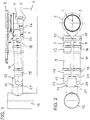
- the drain fitting shown comprises a drain body 1, which has an odor trap or forms one.
- the container-like drain body 1 has an inlet opening 2 on its upper side, which is surrounded by a sealing ring 3 which, when the drain fitting is installed on, for example, a shower tray 4, lies sealingly on its underside in the area of the drain.
- the bottom 5 of the drain body 1 forms an essentially flat standing surface with which the drain body 1 can be arranged on an unfinished floor 6.
- drain body 1 On the drain body 1, two connecting pieces 7, 8 for connecting two drain pipes 9, 10 are formed, via which the drain body 1 is releasably connected to a transition piece 11, which is finally connected to a downpipe 12 or another sewer pipe.
- the total free cross section of the drain pipes 9, 10 is considerably larger than the free cross section of a conventional drain pipe with a circular cross section.
- the connecting pieces 7, 8 are aligned with one another in such a way that the drainage pipes 9, 10 connected to them run essentially parallel to one another. It can also be seen that the connecting pieces 7, 8 each have a pipe joint 13, 14.
- the pipe joints 13, 14 are designed in the manner of a ball and socket joint and are arranged in such a way that they allow pivoting of the connecting pieces 7, 8 and the drainage pipes 9, 10 connected to them about a common pivot axis.
- the drain pipes 9, 10 have a circular cross section, with sleeve-like connecting sections 15, 16 being provided at their ends associated with the connecting pieces 7, 8 of the drain body 1. Corresponding sleeve-like connecting sections 17, 18 are formed on connecting pieces 19, 20 of the transition piece 11.
- the transition piece 11 has an essentially cylindrical pipe section 21 with a bell-shaped end 22, on which the connecting pieces 19, 20 are integrally formed.
- the connecting pieces 19, 20 open into the cylindrical pipe section 21 via arcuate sections 23, 24.
- Fig. 2 it can be seen that the through the connecting pieces 7, 8; 19, 20 and drain pipes 9, 10 defined overall width is not greater than the overall width of the drain body 1. Furthermore, in Fig. 1 It can be seen that the connecting pieces 7, 8 formed on the drain body 1 ′ are arranged such that their underside 25 is at a higher level than the underside 26 of the drain body 1. The vertical distance H between the bottom 25 the connection piece 7, 8 and the underside 26 of the drain body 1 is at least 20 mm, preferably at least 30 mm.
- drain fitting is not limited to the embodiment described above. Rather, a large number of variants are possible which make use of the inventive concept specified in the claims even if the design is fundamentally different.
- the drain body 1 of the drain fitting can also be connected to the transition piece 11 via more than two drain pipes.
- the drain fitting according to the invention can not only be used for flat shower trays, shower trays and bathtubs. Their advantages can also be used in particular with floor drains, for example with floor-level, tiled nozzles.
Landscapes
- Engineering & Computer Science (AREA)
- Health & Medical Sciences (AREA)
- Life Sciences & Earth Sciences (AREA)
- Hydrology & Water Resources (AREA)
- Public Health (AREA)
- Water Supply & Treatment (AREA)
- Environmental & Geological Engineering (AREA)
- Sink And Installation For Waste Water (AREA)
Description
- Die Erfindung betrifft eine Ablaufgarnitur für Duschen oder Badewannen, mit einem einen Geruchverschluss bildenden oder aufweisenden Ablaufkörper und einem Übergangsstück zum Anschluss an eine Abwasserleitung, wobei an dem Ablaufkörper und dem Übergangsstück jeweils mindestens ein Anschlussstutzen zum Anschluss eines Ablaufrohres angeformt ist.
- Durch moderne Duschsysteme, beispielsweise in Form sogenannter Duschtempel oder Regenduschköpfe, wird einer Brausewanne bzw. Duschtasse mitunter mehr Wasser zugeführt, als die heutzutage zur Verfügung stehenden herkömmlichen Ablaufgarnituren abführen können. Es besteht daher der Wunsch nach Duschwannenabläufen mit höherer Ablaufleistung.
- Aus der
JP 2001-248197 A - Ein Adapterstück für Ablaufrohre ist aus der
JP 06-306903 A - Aus der
DE 199 09 138 A1 ist eine Ablaufgarnitur bekannt, die den Ablaufkörper einer Badewanne über ein einen Teleskopabschnitt und ein Kugelgelenk aufweisendes Ablaufrohr mit der Abwasserleitung verbindet. - Die
JP 2002-088842 A - Die
CN 101 096 857 A offenbart eine Abwassersammelrohr-Verbindungsstelle, mit einem Sammelrohrkörper, der außerhalb eines Gebäudes im Erdreich installiert wird. An dem Sammelrohrkörper ist ein horizontaler Rohrstutzen zum Anschluss von mehreren, insbesondere vier Ablaufrohren angeformt, wobei die Ablaufrohre verschiedenen Verbrauchsstellen, z.B. einer Küche, einer Toilette und einer Waschmaschine zugeordnet sind und durch eine Wand des Gebäudes hindurch nach außen verlaufen. Der horizontale Rohrstutzen besitzt einen Muffenabschnitt mit ovalem Querschnitt, in den entsprechend oval ausgebildetes Adapterstück formschlüssig eingesetzt ist. Das Adapterstück weist eine Trennwand auf, in der eine der Anzahl der anzuschließenden Ablaufrohren entsprechende Anzahl von Durchgangsöffnungen ausgebildet ist.. Die jeweilige Durchgangsöffnung ist mit einer Muffe umgeben, in die das zugeordnete Ablaufrohr formschlüssig eingesteckt wird. Die an den Durchgangsöffnungen angeordneten Muffen sind so ausgerichtet, dass die darin eingesteckten Ablaufrohre im Wesentlichen parallel zueinander verlaufen. - Die
JP 2007 211417 A - Die
EP 1 223 374 A2 beschreibt ein Rohrleitungssystem zur Abführung von Abwässern in Gebäudeinstallationen. Das Rohrleitungssystem ist abschnittsweise aus miteinander verbindbaren Rohrstücken und/oder Formstücken und/oder Verbindungsstücken gebildet, aus denen der jeweils benötigte Verlauf des Rohrleitungssystems zusammensetzbar ist. Die Rohrstücke, Formstücke und/oder Verbindungsstücke weisen einen senkrecht zur Fließrichtung des Abwassers im Wesentlichen nicht-kreis-symmetrischen Querschnitt auf, beispielsweise einen ovalisierten oder einen im Wesentlichen kastenförmigen Querschnitt. Dieses Rohrleitungssystem kann derart an Montageflächen befestigt werden, dass die Rohrstücke, Formstücke und/oder Verbindungsstücke weniger weit von den Montageflächen hervorkragen als hydraulisch äquivalent dimensionierte Rohrleitungssysteme kreissymmetrischen Querschnittes. Das Rohrleitungssystem kann dabei insbesondere auf oder an Außenmauern von Gebäuden montiert werden, indem es innerhalb von Dämmschichten auf der Außenmauer eines Gebäudes eingebracht wird und somit verdeckt verläuft. - Des Weiteren sind Badewannen mit Türen als Ein- bzw. Ausstiegshilfen bekannt, wobei das Öffnen der Badewannentür nur dann möglich ist, wenn das Badewasser vollständig abgelaufen ist. Auch insoweit besteht der Wunsch nach Ablaufgarnituren mit einer erhöhten Ablaufleistung, so dass der Benutzer einer solchen Badewanne diese wesentlich schneller verlassen kann.
- Insbesondere in Krankenhäusern und Pflegeheimen besteht der Wunsch nach Ablaufgarnituren mit hoher Ablaufleistung, um ein möglichst schnelles Baden der Patienten bzw. zu pflegenden Personen zu ermöglichen.
- Der vorliegenden Erfindung liegt daher die Aufgabe zugrunde, eine Ablaufgarnitur der eingangs genannten Art bereitzustellen, die bei relativ kompakter Baugröße eine erhöhte Ablaufleistung bietet. Der übliche Ablaufquerschnitt der Bade- oder Duschwanne soll dabei nicht vergrößert, sondern eher minimiert werden.
- Gelöst wird diese Aufgabe durch eine Ablaufgarnitur mit den Merkmalen des Anspruchs 1. Bevorzugte und vorteilhafte Ausgestaltungen der Erfindung sind in den Unteransprüchen angegeben.
- Die erfindungsgemäße Ablaufgarnitur ist dadurch gekennzeichnet, dass der Ablaufkörper mit dem Übergangsstück über mehrere Ablaufrohre verbunden ist, deren freier Querschnitt größer als der freie Querschnitt eines herkömmlichen einzelnen Ablaufrohres mit kreisrundem Querschnitt ist, wobei der Ablaufkörper und das Übergangsstück jeweils mindestens zwei Anschlussstutzen zum Anschluss der Ablaufrohre aufweisen, und wobei die am Ablaufkörper angeformten Anschlussstutzen so angeordnet sind, dass sich deren Unterseite auf einem höheren Niveau als die Unterseite des Ablaufkörpers befindet.
- Durch die erfindungsgemäße Lösung wird eine Ablaufgarnitur mit erhöhter Ablaufleistung für Duschen und Badewannen zur Verfügung gestellt. Die Bauhöhe und Baubreite der Ablaufgarnitur muss hierzu nicht gegenüber herkömmlichen Ablaufgarnituren vergrößert werden. Die erfindungsgemäße Lösung erlaubt es insbesondere, den Abgangsstutzen am Ablaufkörper gegenüber dem unter der Dusche oder Badewanne befindlichen Rohfußboden relativ hoch anzuordnen, so dass sich in dem zum Übergangsstück führenden Ablaufrohr eine gute Gefällesituation ergibt, die einer Ablagerung von Schmutz und/oder Haaren im Ablaufrohr entgegenwirkt.
- Die erfindungsgemäße Ablaufgarnitur ermöglicht bei relativ kompakter Baugröße und zugleich hoher Ablaufleistung die Realisierung einer Rohrgelenkverbindung, die den Anschluss bzw. die Lageanpassung der Ablaufgarnitur in Bezug auf eine-Abwasserleitung (Fallleitung) erleichtern kann. Die mindestens zwei Ablaufrohre weisen dabei vorzugsweise den gleichen kreisrunden Querschnitt auf und verlaufen im Wesentlichen parallel zueinander.
- Nachfolgend wird die Erfindung anhand einer ein Ausführungsbeispiel darstellenden Zeichnung näher erläutert. Es zeigen:
- Fig. 1
- ein Ausführungsbeispiel einer erfindungsgemäßen Ablaufgarnitur in Seitenansicht;
- Fig. 2
- eine Draufsicht auf die Ablaufgarnitur der
Fig. 2 ; und - Fig. 3
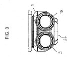
- eine vergrößerte Querschnittansicht entlang der Schnittlinie A-A der
Fig. 1 . - Die in den
Figuren 1 bis 3 dargestellte Ablaufgarnitur umfasst einen Ablaufkörper 1, der einen Geruchverschluss aufweist oder einen solchen bildet. Der behälterartige Ablaufkörper 1 weist an seiner Oberseite eine Einlassöffnung 2 auf, die von einem Dichtring 3 umgeben ist, der bei der Montage der Ablaufgarnitur an zum Beispiel einer Duschtasse 4 dichtend an deren Unterseite im Bereich des Ablaufs anliegt. Der Boden 5 des Ablaufkörpers 1 bildet eine im Wesentlichen eben ausgeführte Standfläche, mit der der Ablaufkörper 1 auf einen Rohfußboden 6 angeordnet werden kann. - An dem Ablaufkörper 1 sind zwei Anschlussstutzen 7, 8 zum Anschluss zweier Ablaufrohre 9, 10 angeformt, über die der Ablaufkörper 1 mit einem Übergangsstück 11 lösbar verbunden ist, das schließlich an einer Fallleitung 12 oder einer anderen Abwasserleitung angeschlossen ist. Der freie Gesamtquerschnitt der Ablaufrohre 9, 10 ist erheblich größer als der freie Querschnitt eines herkömmlichen Ablaufrohres mit kreisrundem Querschnitt.
- Die Anschlussstutzen 7, 8 sind so zueinander ausgerichtet, dass die daran angeschlossenen Ablaufrohre 9, 10 im wesentlichen parallel zueinander verlaufen. Ferner ist zu erkennen, dass die Anschlussstutzen 7, 8 jeweils ein Rohrgelenk 13, 14 aufweisen. Die Rohrgelenke 13, 14 sind nach Art eines Kugelgelenks ausgeführt und so angeordnet, dass sie ein Schwenken der Anschlussstutzen 7, 8 und der daran angeschlossenen Ablaufrohre 9, 10 um eine gemeinsame Schwenkachse ermöglichen.
- Die Ablaufrohre 9, 10 besitzen einen kreisrunden Querschnitt, wobei sie an ihren den Anschlussstutzen 7, 8 des Ablaufkörpers 1 zugeordneten Enden muffenartige Verbindungsabschnitte 15, 16 aufweisen. Entsprechende muffenartige Verbindungsabschnitte 17, 18 sind an Anschlussstutzen 19, 20 des Übergangsstückes 11 ausgebildet.
- Das Übergangsstück 11 weist einen im Wesentlichen zylindrischen Rohrabschnitt 21 mit einem glockenförmigen Ende 22 auf, an das die Anschlussstutzen 19, 20 angeformt sind. Die Anschlussstutzen 19, 20 münden über bogenförmige Abschnitte 23, 24 in den zylindrischen Rohrabschnitt 21.
- In
Fig. 2 ist zu erkennen, dass die durch die Anschlussstutzen 7, 8; 19, 20 und Ablaufrohre 9, 10 definierte Baubreite nicht größer als die Baubreite des Ablaufkörpers 1 ist. Ferner ist inFig. 1 zu erkennen, dass die am Ablaufkörper 1' angeformten Anschlussstutzen 7, 8 so angeordnet sind, dass sich deren Unterseite 25 auf einem höheren Niveau als die Unterseite 26 des Ablaufkörpers 1 befindet. Der vertikale Abstand H zwischen der Unterseite 25 der Anschlussstutzen 7, 8 und der Unterseite 26 des Ablaufkörpers 1 beträgt mindestens 20 mm, vorzugsweise mindestens 30 mm. - Die Ausführung der erfindungsgemäßen Ablaufgarnitur ist nicht auf das vorstehend beschriebene Ausführungsbeispiel beschränkt. Vielmehr sind eine Vielzahl von Varianten möglich, die auch bei grundsätzlich abweichender Ausführung von dem in den Ansprüchen angegebenen Erfindungsgedanken Gebrauch machen. So kann der Ablaufkörper 1 der Ablaufgarnitur beispielsweise auch über mehr als zwei Ablaufrohre mit dem Übergangsstück 11 verbunden sein.
- Die erfindungsgemäße Ablaufgarnitur lässt sich nicht nur bei flachen Duschtassen, Duschwannen und Badewannen anwenden. Ihre Vorteile lassen sich insbesondere auch bei Bodenabläufen, zum Beispiel bei bodengleichen, gefliesten Düschen nutzen.
Claims (5)
- Ablaufgarnitur für Duschen oder Badewannen, mit einem einen Geruchverschluss bildenden oder aufweisenden Ablaufkörper (1) und einem Übergangsstück (11) zum Anschluss an eine Abwasserleitung (12), wobei an dem Ablaufkörper und dem Übergangsstück jeweils mindestens ein Anschlussstutzen (7, 8, 19, 20) zum Anschluss eines Ablaufrohres angeformt ist, dadurch gekennzeichnet, dass der Ablaufkörper (1) mit dem Übergangsstück (11) über mehrere Ablaufrohre (9, 10) verbunden ist, deren freier Querschnitt größer als der freie Querschnitt eines herkömmlichen einzelnen Ablaufrohres mit kreisrundem Querschnitt ist, wobei der Ablaufkörper (1) und das Übergangsstück (11) jeweils mindestens zwei Anschlussstutzen (7, 8, 19, 20) zum Anschluss der Ablaufrohre (9, 10) aufweisen, und wobei die am Ablaufkörper (1) angeformten Anschlussstutzen (7, 8) so angeordnet sind, dass sich deren Unterseite (25) auf einem höheren Niveau als die Unterseite (26) des Ablaufkörpers (1) befindet.
- Ablaufgarnitur nach Anspruch 1,
dadurch gekennzeichnet, dass die am Ablaufkörper (1) und am Übergangsstück (11) ausgebildeten Anschlussstutzen (7, 8, 19, 20) so zueinander ausgerichtet sind, dass die daran angeschlossenen mehreren Ablaufrohre (9, 10) im Wesentlichen parallel zueinander verlaufen. - Ablaufgarnitur nach Anspruch 1 oder 2,
dadurch gekennzeichnet, dass die Anschlussstutzen (7, 8) jeweils ein Rohrgelenk (13, 14) aufweisen. - Ablaufgarnitur nach Anspruch 3,
dadurch gekennzeichnet, dass die Rohrgelenke (13, 14) so angeordnet sind, dass sie ein Schwenken der Anschlussstutzen (7, 8) um eine gemeinsame Schwenkachse ermöglichen. - Ablaufgarnitur nach einem der Ansprüche 1 bis 4,
dadurch gekennzeichnet, dass der vertikale Abstand (H) zwischen der Unterseite (25) der am Ablaufkörper angeformten Anschlussstutzen (7, 8) und der Unterseite (26) des Ablaufkörpers (1) mindestens 20 mm, vorzugsweise mindestens 30 mm beträgt.
Applications Claiming Priority (1)
| Application Number | Priority Date | Filing Date | Title |
|---|---|---|---|
| DE202007009710U DE202007009710U1 (de) | 2007-07-10 | 2007-07-10 | Ablaufgarnitur für Duschen oder Badewannen |
Publications (3)
| Publication Number | Publication Date |
|---|---|
| EP2014840A2 EP2014840A2 (de) | 2009-01-14 |
| EP2014840A3 EP2014840A3 (de) | 2010-08-25 |
| EP2014840B1 true EP2014840B1 (de) | 2021-02-24 |
Family
ID=39862997
Family Applications (1)
| Application Number | Title | Priority Date | Filing Date |
|---|---|---|---|
| EP08103885.3A Active EP2014840B1 (de) | 2007-07-10 | 2008-05-09 | Ablaufgarnitur für Duschen oder Badewannen |
Country Status (2)
| Country | Link |
|---|---|
| EP (1) | EP2014840B1 (de) |
| DE (1) | DE202007009710U1 (de) |
Families Citing this family (6)
| Publication number | Priority date | Publication date | Assignee | Title |
|---|---|---|---|---|
| DE202008006611U1 (de) * | 2008-05-15 | 2009-10-01 | Viega Gmbh & Co. Kg | Ablaufgarnitur für Wasch- oder Spülbecken |
| ITPI20100059A1 (it) * | 2010-05-21 | 2011-11-22 | Benz Ursula | Impianto idraulico di scarico di acque grigie da un'utenza |
| DE202011102926U1 (de) * | 2011-06-28 | 2012-10-10 | Poresta Systems Gmbh | Duschbodenelement |
| FR3010099B1 (fr) * | 2013-09-02 | 2021-11-26 | Lazer | Bonde siphoide a sortie horizontale pour receveur de douche |
| NO337435B1 (no) * | 2013-12-17 | 2016-04-11 | Skorga Innovation As | Sluk |
| DE102019127094A1 (de) * | 2019-10-09 | 2021-04-15 | ACO Severin Ahlmann GmbH & Co Kommanditgesellschaft | Geruchsverschluss, Ablauftopf und Ablaufsystem |
Citations (3)
| Publication number | Priority date | Publication date | Assignee | Title |
|---|---|---|---|---|
| EP1223374A2 (de) * | 2000-12-14 | 2002-07-17 | Mete Demiriz | Rohrleitungssystem, insbesondere zur Abführung von Abwässern in Gebäudeinstallationen |
| JP2007211417A (ja) * | 2006-02-07 | 2007-08-23 | Noriatsu Kojima | 集合管継手 |
| CN101096857A (zh) * | 2006-06-29 | 2008-01-02 | 安隆化成株式会社 | 管式集水接头和具有管式集水接头的集水排水装置 |
Family Cites Families (6)
| Publication number | Priority date | Publication date | Assignee | Title |
|---|---|---|---|---|
| JPH06306903A (ja) * | 1993-04-22 | 1994-11-01 | Aron Kasei Co Ltd | 排水マス構造体とこれを用いた排水マス |
| DE19909138A1 (de) * | 1999-03-03 | 2000-09-07 | Correcta Gmbh | Wannenträger |
| JP3499492B2 (ja) * | 2000-03-07 | 2004-02-23 | 日本総合住生活株式会社 | 排水管のスラブ上配管システム |
| JP4536236B2 (ja) * | 2000-09-19 | 2010-09-01 | クボタシーアイ株式会社 | 排水管 |
| DE102005036576B4 (de) * | 2004-12-23 | 2018-04-19 | Dallmer Gmbh & Co.Kg | Ablaufvorrichtung für die Anordnung an einer Bodenplatte mit einer Öffung für Abwasser |
| WO2008135705A1 (en) * | 2007-05-04 | 2008-11-13 | Dlp Limited | Shower drainage system having slimline waste conduit device |
-
2007
- 2007-07-10 DE DE202007009710U patent/DE202007009710U1/de not_active Expired - Lifetime
-
2008
- 2008-05-09 EP EP08103885.3A patent/EP2014840B1/de active Active
Patent Citations (3)
| Publication number | Priority date | Publication date | Assignee | Title |
|---|---|---|---|---|
| EP1223374A2 (de) * | 2000-12-14 | 2002-07-17 | Mete Demiriz | Rohrleitungssystem, insbesondere zur Abführung von Abwässern in Gebäudeinstallationen |
| JP2007211417A (ja) * | 2006-02-07 | 2007-08-23 | Noriatsu Kojima | 集合管継手 |
| CN101096857A (zh) * | 2006-06-29 | 2008-01-02 | 安隆化成株式会社 | 管式集水接头和具有管式集水接头的集水排水装置 |
Also Published As
| Publication number | Publication date |
|---|---|
| DE202007009710U1 (de) | 2008-11-20 |
| EP2014840A2 (de) | 2009-01-14 |
| EP2014840A3 (de) | 2010-08-25 |
Similar Documents
| Publication | Publication Date | Title |
|---|---|---|
| EP2014840B1 (de) | Ablaufgarnitur für Duschen oder Badewannen | |
| DE112010003584B4 (de) | Notfall-waschsystem | |
| EP2568089B1 (de) | Verwendung einer WC-Anschlussvorrichtung und eines Dusch-WCs | |
| EP2584107A1 (de) | Sanitäranordnung | |
| DE202018006705U1 (de) | Spültoilette | |
| EP2157247B1 (de) | Ablauf | |
| DE202008011010U1 (de) | Ablauf | |
| DE202021106357U1 (de) | Toilette mit Wasserspülung | |
| DE60200339T2 (de) | Ablaufrinne und Nachspülungssystem für Melkstände | |
| DE1658261C3 (de) | Spülwasserverteiler für Wasserklosettbecken | |
| DE102014012288A1 (de) | Regenwasserfilter | |
| DE202005019964U1 (de) | Ablaufsystem | |
| EP1862602B1 (de) | Becken mit verdecktem Überlauf und zugehöriger Ablaufgarnitur | |
| EP3708725B1 (de) | Siphoneinrichtung | |
| DE10065985B4 (de) | Toilettenschüssel | |
| EP2119837B1 (de) | Ablaufgarnitur für Wasch- oder Spülbecken | |
| DE69727166T2 (de) | Fertigelement für die wirksame Kupplung eines Installationsblocks an einem Flüssigkeitsver- und Entsorgungssystem | |
| WO2005111326A1 (de) | Geruchsverschluss | |
| DE102014111784A1 (de) | Vorrichtung für einen beabstandet zu einer Wand im Boden eines Raumes angeordneten Bodenablauf | |
| EP3741919B1 (de) | Kugelabzweig | |
| DE29821457U1 (de) | Heizkörper für eine Zentralheizungsanlage | |
| EP3650277B1 (de) | Reisemobil | |
| DE69021691T2 (de) | Abflusssiphon für Sanitärapparat. | |
| DE102011013296A1 (de) | Ablauf sowie Sanitärwanne mit dem Ablauf | |
| AT412791B (de) | Adapter zum anschluss eines flüssigkeitsspenders an einem behälter zum sammeln von spülwasser für ein wc |
Legal Events
| Date | Code | Title | Description |
|---|---|---|---|
| PUAI | Public reference made under article 153(3) epc to a published international application that has entered the european phase |
Free format text: ORIGINAL CODE: 0009012 |
|
| AK | Designated contracting states |
Kind code of ref document: A2 Designated state(s): AT BE BG CH CY CZ DE DK EE ES FI FR GB GR HR HU IE IS IT LI LT LU LV MC MT NL NO PL PT RO SE SI SK TR |
|
| AX | Request for extension of the european patent |
Extension state: AL BA MK RS |
|
| PUAL | Search report despatched |
Free format text: ORIGINAL CODE: 0009013 |
|
| AK | Designated contracting states |
Kind code of ref document: A3 Designated state(s): AT BE BG CH CY CZ DE DK EE ES FI FR GB GR HR HU IE IS IT LI LT LU LV MC MT NL NO PL PT RO SE SI SK TR |
|
| AX | Request for extension of the european patent |
Extension state: AL BA MK RS |
|
| 17P | Request for examination filed |
Effective date: 20101008 |
|
| AKX | Designation fees paid |
Designated state(s): AT BE BG CH CY CZ DE DK EE ES FI FR GB GR HR HU IE IS IT LI LT LU LV MC MT NL NO PL PT RO SE SI SK TR |
|
| 17Q | First examination report despatched |
Effective date: 20130628 |
|
| RAP1 | Party data changed (applicant data changed or rights of an application transferred) |
Owner name: VIEGA GMBH & CO. KG |
|
| RAP1 | Party data changed (applicant data changed or rights of an application transferred) |
Owner name: VIEGA TECHNOLOGY GMBH & CO. KG |
|
| APBK | Appeal reference recorded |
Free format text: ORIGINAL CODE: EPIDOSNREFNE |
|
| APBN | Date of receipt of notice of appeal recorded |
Free format text: ORIGINAL CODE: EPIDOSNNOA2E |
|
| APBR | Date of receipt of statement of grounds of appeal recorded |
Free format text: ORIGINAL CODE: EPIDOSNNOA3E |
|
| APAV | Appeal reference deleted |
Free format text: ORIGINAL CODE: EPIDOSDREFNE |
|
| APBX | Invitation to file observations in appeal sent |
Free format text: ORIGINAL CODE: EPIDOSNOBA2E |
|
| APBZ | Receipt of observations in appeal recorded |
Free format text: ORIGINAL CODE: EPIDOSNOBA4E |
|
| APBT | Appeal procedure closed |
Free format text: ORIGINAL CODE: EPIDOSNNOA9E |
|
| GRAP | Despatch of communication of intention to grant a patent |
Free format text: ORIGINAL CODE: EPIDOSNIGR1 |
|
| STAA | Information on the status of an ep patent application or granted ep patent |
Free format text: STATUS: GRANT OF PATENT IS INTENDED |
|
| INTG | Intention to grant announced |
Effective date: 20201007 |
|
| GRAS | Grant fee paid |
Free format text: ORIGINAL CODE: EPIDOSNIGR3 |
|
| GRAJ | Information related to disapproval of communication of intention to grant by the applicant or resumption of examination proceedings by the epo deleted |
Free format text: ORIGINAL CODE: EPIDOSDIGR1 |
|
| GRAL | Information related to payment of fee for publishing/printing deleted |
Free format text: ORIGINAL CODE: EPIDOSDIGR3 |
|
| STAA | Information on the status of an ep patent application or granted ep patent |
Free format text: STATUS: EXAMINATION IS IN PROGRESS |
|
| INTC | Intention to grant announced (deleted) | ||
| GRAP | Despatch of communication of intention to grant a patent |
Free format text: ORIGINAL CODE: EPIDOSNIGR1 |
|
| STAA | Information on the status of an ep patent application or granted ep patent |
Free format text: STATUS: GRANT OF PATENT IS INTENDED |
|
| GRAA | (expected) grant |
Free format text: ORIGINAL CODE: 0009210 |
|
| STAA | Information on the status of an ep patent application or granted ep patent |
Free format text: STATUS: THE PATENT HAS BEEN GRANTED |
|
| INTG | Intention to grant announced |
Effective date: 20210113 |
|
| AK | Designated contracting states |
Kind code of ref document: B1 Designated state(s): AT BE BG CH CY CZ DE DK EE ES FI FR GB GR HR HU IE IS IT LI LT LU LV MC MT NL NO PL PT RO SE SI SK TR |
|
| REG | Reference to a national code |
Ref country code: GB Ref legal event code: FG4D Free format text: NOT ENGLISH |
|
| REG | Reference to a national code |
Ref country code: CH Ref legal event code: EP |
|
| REG | Reference to a national code |
Ref country code: AT Ref legal event code: REF Ref document number: 1364598 Country of ref document: AT Kind code of ref document: T Effective date: 20210315 |
|
| REG | Reference to a national code |
Ref country code: IE Ref legal event code: FG4D Free format text: LANGUAGE OF EP DOCUMENT: GERMAN |
|
| REG | Reference to a national code |
Ref country code: DE Ref legal event code: R096 Ref document number: 502008017185 Country of ref document: DE |
|
| REG | Reference to a national code |
Ref country code: LT Ref legal event code: MG9D |
|
| REG | Reference to a national code |
Ref country code: NL Ref legal event code: MP Effective date: 20210224 |
|
| PG25 | Lapsed in a contracting state [announced via postgrant information from national office to epo] |
Ref country code: HR Free format text: LAPSE BECAUSE OF FAILURE TO SUBMIT A TRANSLATION OF THE DESCRIPTION OR TO PAY THE FEE WITHIN THE PRESCRIBED TIME-LIMIT Effective date: 20210224 Ref country code: FI Free format text: LAPSE BECAUSE OF FAILURE TO SUBMIT A TRANSLATION OF THE DESCRIPTION OR TO PAY THE FEE WITHIN THE PRESCRIBED TIME-LIMIT Effective date: 20210224 Ref country code: GR Free format text: LAPSE BECAUSE OF FAILURE TO SUBMIT A TRANSLATION OF THE DESCRIPTION OR TO PAY THE FEE WITHIN THE PRESCRIBED TIME-LIMIT Effective date: 20210525 Ref country code: LT Free format text: LAPSE BECAUSE OF FAILURE TO SUBMIT A TRANSLATION OF THE DESCRIPTION OR TO PAY THE FEE WITHIN THE PRESCRIBED TIME-LIMIT Effective date: 20210224 Ref country code: BG Free format text: LAPSE BECAUSE OF FAILURE TO SUBMIT A TRANSLATION OF THE DESCRIPTION OR TO PAY THE FEE WITHIN THE PRESCRIBED TIME-LIMIT Effective date: 20210524 Ref country code: NO Free format text: LAPSE BECAUSE OF FAILURE TO SUBMIT A TRANSLATION OF THE DESCRIPTION OR TO PAY THE FEE WITHIN THE PRESCRIBED TIME-LIMIT Effective date: 20210524 Ref country code: PT Free format text: LAPSE BECAUSE OF FAILURE TO SUBMIT A TRANSLATION OF THE DESCRIPTION OR TO PAY THE FEE WITHIN THE PRESCRIBED TIME-LIMIT Effective date: 20210624 |
|
| PG25 | Lapsed in a contracting state [announced via postgrant information from national office to epo] |
Ref country code: PL Free format text: LAPSE BECAUSE OF FAILURE TO SUBMIT A TRANSLATION OF THE DESCRIPTION OR TO PAY THE FEE WITHIN THE PRESCRIBED TIME-LIMIT Effective date: 20210224 Ref country code: LV Free format text: LAPSE BECAUSE OF FAILURE TO SUBMIT A TRANSLATION OF THE DESCRIPTION OR TO PAY THE FEE WITHIN THE PRESCRIBED TIME-LIMIT Effective date: 20210224 Ref country code: NL Free format text: LAPSE BECAUSE OF FAILURE TO SUBMIT A TRANSLATION OF THE DESCRIPTION OR TO PAY THE FEE WITHIN THE PRESCRIBED TIME-LIMIT Effective date: 20210224 Ref country code: SE Free format text: LAPSE BECAUSE OF FAILURE TO SUBMIT A TRANSLATION OF THE DESCRIPTION OR TO PAY THE FEE WITHIN THE PRESCRIBED TIME-LIMIT Effective date: 20210224 |
|
| PG25 | Lapsed in a contracting state [announced via postgrant information from national office to epo] |
Ref country code: IS Free format text: LAPSE BECAUSE OF FAILURE TO SUBMIT A TRANSLATION OF THE DESCRIPTION OR TO PAY THE FEE WITHIN THE PRESCRIBED TIME-LIMIT Effective date: 20210624 |
|
| PG25 | Lapsed in a contracting state [announced via postgrant information from national office to epo] |
Ref country code: EE Free format text: LAPSE BECAUSE OF FAILURE TO SUBMIT A TRANSLATION OF THE DESCRIPTION OR TO PAY THE FEE WITHIN THE PRESCRIBED TIME-LIMIT Effective date: 20210224 Ref country code: CZ Free format text: LAPSE BECAUSE OF FAILURE TO SUBMIT A TRANSLATION OF THE DESCRIPTION OR TO PAY THE FEE WITHIN THE PRESCRIBED TIME-LIMIT Effective date: 20210224 |
|
| REG | Reference to a national code |
Ref country code: DE Ref legal event code: R097 Ref document number: 502008017185 Country of ref document: DE |
|
| PG25 | Lapsed in a contracting state [announced via postgrant information from national office to epo] |
Ref country code: SK Free format text: LAPSE BECAUSE OF FAILURE TO SUBMIT A TRANSLATION OF THE DESCRIPTION OR TO PAY THE FEE WITHIN THE PRESCRIBED TIME-LIMIT Effective date: 20210224 Ref country code: ES Free format text: LAPSE BECAUSE OF FAILURE TO SUBMIT A TRANSLATION OF THE DESCRIPTION OR TO PAY THE FEE WITHIN THE PRESCRIBED TIME-LIMIT Effective date: 20210224 Ref country code: DK Free format text: LAPSE BECAUSE OF FAILURE TO SUBMIT A TRANSLATION OF THE DESCRIPTION OR TO PAY THE FEE WITHIN THE PRESCRIBED TIME-LIMIT Effective date: 20210224 Ref country code: RO Free format text: LAPSE BECAUSE OF FAILURE TO SUBMIT A TRANSLATION OF THE DESCRIPTION OR TO PAY THE FEE WITHIN THE PRESCRIBED TIME-LIMIT Effective date: 20210224 |
|
| REG | Reference to a national code |
Ref country code: CH Ref legal event code: PL |
|
| PLBE | No opposition filed within time limit |
Free format text: ORIGINAL CODE: 0009261 |
|
| STAA | Information on the status of an ep patent application or granted ep patent |
Free format text: STATUS: NO OPPOSITION FILED WITHIN TIME LIMIT |
|
| GBPC | Gb: european patent ceased through non-payment of renewal fee |
Effective date: 20210524 |
|
| PG25 | Lapsed in a contracting state [announced via postgrant information from national office to epo] |
Ref country code: CH Free format text: LAPSE BECAUSE OF NON-PAYMENT OF DUE FEES Effective date: 20210531 Ref country code: LU Free format text: LAPSE BECAUSE OF NON-PAYMENT OF DUE FEES Effective date: 20210509 Ref country code: MC Free format text: LAPSE BECAUSE OF FAILURE TO SUBMIT A TRANSLATION OF THE DESCRIPTION OR TO PAY THE FEE WITHIN THE PRESCRIBED TIME-LIMIT Effective date: 20210224 Ref country code: LI Free format text: LAPSE BECAUSE OF NON-PAYMENT OF DUE FEES Effective date: 20210531 |
|
| 26N | No opposition filed |
Effective date: 20211125 |
|
| REG | Reference to a national code |
Ref country code: BE Ref legal event code: MM Effective date: 20210531 |
|
| PG25 | Lapsed in a contracting state [announced via postgrant information from national office to epo] |
Ref country code: SI Free format text: LAPSE BECAUSE OF FAILURE TO SUBMIT A TRANSLATION OF THE DESCRIPTION OR TO PAY THE FEE WITHIN THE PRESCRIBED TIME-LIMIT Effective date: 20210224 |
|
| PG25 | Lapsed in a contracting state [announced via postgrant information from national office to epo] |
Ref country code: IE Free format text: LAPSE BECAUSE OF NON-PAYMENT OF DUE FEES Effective date: 20210509 Ref country code: GB Free format text: LAPSE BECAUSE OF NON-PAYMENT OF DUE FEES Effective date: 20210524 |
|
| PG25 | Lapsed in a contracting state [announced via postgrant information from national office to epo] |
Ref country code: IS Free format text: LAPSE BECAUSE OF FAILURE TO SUBMIT A TRANSLATION OF THE DESCRIPTION OR TO PAY THE FEE WITHIN THE PRESCRIBED TIME-LIMIT Effective date: 20210624 Ref country code: FR Free format text: LAPSE BECAUSE OF NON-PAYMENT OF DUE FEES Effective date: 20210531 |
|
| PG25 | Lapsed in a contracting state [announced via postgrant information from national office to epo] |
Ref country code: BE Free format text: LAPSE BECAUSE OF NON-PAYMENT OF DUE FEES Effective date: 20210531 |
|
| PGFP | Annual fee paid to national office [announced via postgrant information from national office to epo] |
Ref country code: AT Payment date: 20220523 Year of fee payment: 15 |
|
| PG25 | Lapsed in a contracting state [announced via postgrant information from national office to epo] |
Ref country code: HU Free format text: LAPSE BECAUSE OF FAILURE TO SUBMIT A TRANSLATION OF THE DESCRIPTION OR TO PAY THE FEE WITHIN THE PRESCRIBED TIME-LIMIT; INVALID AB INITIO Effective date: 20080509 Ref country code: CY Free format text: LAPSE BECAUSE OF FAILURE TO SUBMIT A TRANSLATION OF THE DESCRIPTION OR TO PAY THE FEE WITHIN THE PRESCRIBED TIME-LIMIT Effective date: 20210224 |
|
| REG | Reference to a national code |
Ref country code: AT Ref legal event code: MM01 Ref document number: 1364598 Country of ref document: AT Kind code of ref document: T Effective date: 20230509 |
|
| PG25 | Lapsed in a contracting state [announced via postgrant information from national office to epo] |
Ref country code: AT Free format text: LAPSE BECAUSE OF NON-PAYMENT OF DUE FEES Effective date: 20230509 |
|
| PG25 | Lapsed in a contracting state [announced via postgrant information from national office to epo] |
Ref country code: TR Free format text: LAPSE BECAUSE OF FAILURE TO SUBMIT A TRANSLATION OF THE DESCRIPTION OR TO PAY THE FEE WITHIN THE PRESCRIBED TIME-LIMIT Effective date: 20210224 |
|
| PG25 | Lapsed in a contracting state [announced via postgrant information from national office to epo] |
Ref country code: MT Free format text: LAPSE BECAUSE OF FAILURE TO SUBMIT A TRANSLATION OF THE DESCRIPTION OR TO PAY THE FEE WITHIN THE PRESCRIBED TIME-LIMIT Effective date: 20210224 |
|
| PGFP | Annual fee paid to national office [announced via postgrant information from national office to epo] |
Ref country code: DE Payment date: 20250523 Year of fee payment: 18 |
|
| PGFP | Annual fee paid to national office [announced via postgrant information from national office to epo] |
Ref country code: IT Payment date: 20250526 Year of fee payment: 18 |