EP2015047A2 - Procédé et dispositif de centrage et de fixation d'une pièce à usiner dans une machine d'équilibrage - Google Patents
Procédé et dispositif de centrage et de fixation d'une pièce à usiner dans une machine d'équilibrage Download PDFInfo
- Publication number
- EP2015047A2 EP2015047A2 EP08159494A EP08159494A EP2015047A2 EP 2015047 A2 EP2015047 A2 EP 2015047A2 EP 08159494 A EP08159494 A EP 08159494A EP 08159494 A EP08159494 A EP 08159494A EP 2015047 A2 EP2015047 A2 EP 2015047A2
- Authority
- EP
- European Patent Office
- Prior art keywords
- clamping
- actuating
- chuck
- workpiece
- centering
- Prior art date
- Legal status (The legal status is an assumption and is not a legal conclusion. Google has not performed a legal analysis and makes no representation as to the accuracy of the status listed.)
- Granted
Links
Images


Classifications
-
- B—PERFORMING OPERATIONS; TRANSPORTING
- B23—MACHINE TOOLS; METAL-WORKING NOT OTHERWISE PROVIDED FOR
- B23B—TURNING; BORING
- B23B31/00—Chucks; Expansion mandrels; Adaptations thereof for remote control
- B23B31/02—Chucks
- B23B31/10—Chucks characterised by the retaining or gripping devices or their immediate operating means
- B23B31/12—Chucks with simultaneously-acting jaws, whether or not also individually adjustable
-
- B—PERFORMING OPERATIONS; TRANSPORTING
- B23—MACHINE TOOLS; METAL-WORKING NOT OTHERWISE PROVIDED FOR
- B23B—TURNING; BORING
- B23B31/00—Chucks; Expansion mandrels; Adaptations thereof for remote control
- B23B31/02—Chucks
- B23B31/10—Chucks characterised by the retaining or gripping devices or their immediate operating means
- B23B31/12—Chucks with simultaneously-acting jaws, whether or not also individually adjustable
- B23B31/19—Chucks with simultaneously-acting jaws, whether or not also individually adjustable moving parallel to the axis of the chuck
-
- B—PERFORMING OPERATIONS; TRANSPORTING
- B23—MACHINE TOOLS; METAL-WORKING NOT OTHERWISE PROVIDED FOR
- B23B—TURNING; BORING
- B23B31/00—Chucks; Expansion mandrels; Adaptations thereof for remote control
- B23B31/40—Expansion mandrels
- B23B31/4006—Gripping the work or tool by a split sleeve
- B23B31/4033—Gripping the work or tool by a split sleeve using mechanical transmission through the spindle
-
- G—PHYSICS
- G01—MEASURING; TESTING
- G01M—TESTING STATIC OR DYNAMIC BALANCE OF MACHINES OR STRUCTURES; TESTING OF STRUCTURES OR APPARATUS, NOT OTHERWISE PROVIDED FOR
- G01M1/00—Testing static or dynamic balance of machines or structures
- G01M1/14—Determining imbalance
- G01M1/16—Determining imbalance by oscillating or rotating the body to be tested
- G01M1/24—Performing balancing on elastic shafts, e.g. for crankshafts
-
- B—PERFORMING OPERATIONS; TRANSPORTING
- B23—MACHINE TOOLS; METAL-WORKING NOT OTHERWISE PROVIDED FOR
- B23B—TURNING; BORING
- B23B2270/00—Details of turning, boring or drilling machines, processes or tools not otherwise provided for
- B23B2270/12—Centering of two components relative to one another
-
- Y—GENERAL TAGGING OF NEW TECHNOLOGICAL DEVELOPMENTS; GENERAL TAGGING OF CROSS-SECTIONAL TECHNOLOGIES SPANNING OVER SEVERAL SECTIONS OF THE IPC; TECHNICAL SUBJECTS COVERED BY FORMER USPC CROSS-REFERENCE ART COLLECTIONS [XRACs] AND DIGESTS
- Y10—TECHNICAL SUBJECTS COVERED BY FORMER USPC
- Y10T—TECHNICAL SUBJECTS COVERED BY FORMER US CLASSIFICATION
- Y10T279/00—Chucks or sockets
- Y10T279/10—Expanding
- Y10T279/1004—Collet type
- Y10T279/1008—Fixed jaws and moving cam
-
- Y—GENERAL TAGGING OF NEW TECHNOLOGICAL DEVELOPMENTS; GENERAL TAGGING OF CROSS-SECTIONAL TECHNOLOGIES SPANNING OVER SEVERAL SECTIONS OF THE IPC; TECHNICAL SUBJECTS COVERED BY FORMER USPC CROSS-REFERENCE ART COLLECTIONS [XRACs] AND DIGESTS
- Y10—TECHNICAL SUBJECTS COVERED BY FORMER USPC
- Y10T—TECHNICAL SUBJECTS COVERED BY FORMER US CLASSIFICATION
- Y10T279/00—Chucks or sockets
- Y10T279/26—Chucks or sockets with centering means
-
- Y—GENERAL TAGGING OF NEW TECHNOLOGICAL DEVELOPMENTS; GENERAL TAGGING OF CROSS-SECTIONAL TECHNOLOGIES SPANNING OVER SEVERAL SECTIONS OF THE IPC; TECHNICAL SUBJECTS COVERED BY FORMER USPC CROSS-REFERENCE ART COLLECTIONS [XRACs] AND DIGESTS
- Y10—TECHNICAL SUBJECTS COVERED BY FORMER USPC
- Y10T—TECHNICAL SUBJECTS COVERED BY FORMER US CLASSIFICATION
- Y10T279/00—Chucks or sockets
- Y10T279/29—More than one set of gripping means
-
- Y—GENERAL TAGGING OF NEW TECHNOLOGICAL DEVELOPMENTS; GENERAL TAGGING OF CROSS-SECTIONAL TECHNOLOGIES SPANNING OVER SEVERAL SECTIONS OF THE IPC; TECHNICAL SUBJECTS COVERED BY FORMER USPC CROSS-REFERENCE ART COLLECTIONS [XRACs] AND DIGESTS
- Y10—TECHNICAL SUBJECTS COVERED BY FORMER USPC
- Y10T—TECHNICAL SUBJECTS COVERED BY FORMER US CLASSIFICATION
- Y10T279/00—Chucks or sockets
- Y10T279/33—Member applies axial force component
-
- Y—GENERAL TAGGING OF NEW TECHNOLOGICAL DEVELOPMENTS; GENERAL TAGGING OF CROSS-SECTIONAL TECHNOLOGIES SPANNING OVER SEVERAL SECTIONS OF THE IPC; TECHNICAL SUBJECTS COVERED BY FORMER USPC CROSS-REFERENCE ART COLLECTIONS [XRACs] AND DIGESTS
- Y10—TECHNICAL SUBJECTS COVERED BY FORMER USPC
- Y10T—TECHNICAL SUBJECTS COVERED BY FORMER US CLASSIFICATION
- Y10T29/00—Metal working
- Y10T29/49—Method of mechanical manufacture
- Y10T29/49998—Work holding
Definitions
- the invention relates to a method for centering and clamping a workpiece, in particular a propeller shaft, in a balancing machine and a chuck for carrying out the method.
- the workpieces for fixing the rotation axis are usually provided with a mostly cylindrical centering surface and a radially extending, rotationally symmetrical, mostly planar contact surface, by which the axis of rotation of the workpiece is determined.
- the chuck cooperates with these surfaces receptacles, for example, a radially supporting Zentrierspann emotions, axially supporting clamping surfaces or the like, provided on which the workpiece is clamped by means of clamping elements.
- Cardan shafts are usually mounted in a horizontal position with their ends on two spindles of a balancing machine for balancing, each spindle having a chuck in which the arranged at the propeller shaft end flange is centered and tensioned.
- chucks are used, which are set up so that the flange of the drive shafts in its conical clamping device, which engages in a bore of the flange, centered and radially biased with high actuation force. Subsequently, the flange is pressed with a radial contact surface by means of tie rods and the flange of clamping elements surrounding the outside against a clamping surface of the chuck.
- the invention has for its object to provide a method of the type mentioned, which avoids clamping errors and ensures a very accurate clamping of the workpieces. Furthermore, the method should be automatically carried out. It is a further object of the invention to provide a chuck for a balancing machine, which ensures automatic centering and clamping of workpieces, in particular propeller shafts, with great accuracy.
- the method for achieving the stated object comprises the steps of positioning a workpiece with a centering surface on a centering clamping body of a chuck, pressing a radial contact surface of the workpiece to a clamping surface of the chuck with a radial movement of the workpiece still permitting the first force, centering of the workpiece by tensioning the Zentrierspann stressess against the centering surface of the workpiece, pressing the workpiece with the radial bearing surface to the clamping surface of the chuck with a larger, the workpiece clamping second force.
- the second force is at least a factor of 3 greater than the first force.
- the workpiece is first pressed against the clamping surface of the chuck with a relatively small first force with the flat, radial abutment surface.
- a parallel alignment of the axes of rotation of chuck and workpiece is achieved, but the workpiece is still radially displaceable for the subsequent centering.
- the subsequent tensioning of the Zentrierspannelless therefore the workpiece can be exactly centered, being maintained by the axial action of the first force of the contact between the flat contact surface and the clamping surface and thus the correct alignment of the axis of rotation of the workpiece.
- the axis of rotation of the workpiece is optimally aligned with the axis of rotation of the chuck, so that by the subsequent axial clamping of the workpiece with the much higher second force, the final fixation of the workpiece can be done in the chuck. A biasing of the workpiece is thereby avoided.
- An advantageous device for carrying out the method according to the invention comprises according to the invention, a centering clamping body with a centering, the diameter of which is changeable, a ZentrierspannOSE adjacent, radially extending clamping surface, a movable clamping element for axial pressing of the workpiece to the clamping surface, a first spring element by the centering clamping body is movable into a clamping position, a second spring element, by which the clamping element can be acted upon by a first force, a third spring element, by which the clamping element can be acted upon by a second force, and an axially movable actuating device, through which the centering clamping body and the clamping element against the force of the first and third spring element are movable into a release position.
- the device according to the invention enables the automatic clamping and centering of a workpiece with defined forces and reliably avoids the occurrence of clamping errors.
- the device also has the advantage that it is held without play by the spring elements and therefore no accuracy of the unbalance measurement disturbing vibrations occur.
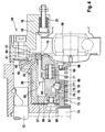
- chuck 1 has a chuck body 2, which is composed of a flange 3 and a housing part 4.
- a centering ring 5 is formed, which serves for centering the flange part 3 on a spindle flange of a balancing machine.
- screws 6 the flange 3 can be attached to the spindle flange.
- the chuck housing 2 has a central bore 7, in which an actuating element 8 is mounted longitudinally movable.
- At the actuator 8 at least two arms 9 are fixed, which extend in the chuck body 2 radially outward.
- the radially outer ends of the arms 9 are each coupled to a pull rod 10 which is mounted longitudinally movably and rotatably in a bore 7 parallel to the axis bore 11 in the chuck body 2.
- the coupling between an arm 9 and a pull rod 10 is designed so that the pull rod 10 can rotate relative to the arm 9. In the axial direction, the coupling is positive and substantially free of play.
- the actuating element 8 On the side facing away from the flange 3 side of the arms 9, the actuating element 8 carries a spring plate 12.
- a plurality of prestressed compression springs 13 are arranged at a uniform distance from each other around the actuating element 8 and clamped between the spring plate 12 and a wall 14 of the housing part 4.
- Each pull rod 10 has within the bore 11 a drive portion 15 with a groove 16 having a helical portion 16a and a straight portion 16b.
- the remote from the flange 3, front end of the tie rod 10 protrudes from the chuck body 2.
- a clamping element 18 is fastened by means of a screw.
- the clamping element 18 has a bore 10 parallel to the axis of the drawbar, in which a shaft 20 of a clamping mushroom 19 and a compression spring 21 are arranged.
- the compression spring 21 surrounds the shaft 20 and is supported at one end on the clamping mushroom 19 and at the other end to the clamping element 18.
- two mutually counterposed stop nuts 22 are arranged, which limit a caused by the compression spring 21 movement of the clamping mushroom 19 in the direction of the chuck body 2.
- the tensioning mushroom 19 can be supported directly on the tensioning element 18.
- the housing part 4 of the chuck housing 2 has a cup-shaped recess 24 in which a mandrel housing 25 is arranged.
- the mandrel housing 25 is centered by centering exactly in the recess 24 and has an annular collar 26 which is fixedly connected by means not shown screws with the housing part 4.
- the collar 26 is centered with a conical lateral surface 28 in a conical section 29 of the housing part 4 and supported in the axial direction.
- the housing part 4 facing away from the front side of the mandrel housing 25 forms a flat, annular clamping surface 27, against which a workpiece 50 by means of the clamping element 18 and the clamping mushroom 19 can be tensioned.
- an actuating sleeve 30 is arranged axially movable with an actuating edge 31 formed in the sleeve bore.
- the actuating sleeve 30 actuates a cylinder clamping body 32 which projects into the actuating sleeve 30 and has a conical actuating surface 33 cooperating with the actuating edge 31.
- the cylinder clamping body 32 has the shape of a slotted sleeve and is mounted on a base body 34 which is disposed in the mandrel housing 25 and fixedly connected thereto.
- the one, front end of the cylinder clamping body 32 protrudes on the side facing away from the housing part 4 from the mandrel housing 25 and is provided with a centering smaller diameter, which forms a clamping edge 35 with its outside.
- the centering section has a supporting edge 36 which adjoins the base body 34 and a stop edge 37, which rests against a shoulder of the base body 34 in the axial direction.
- an actuating body 41 is arranged longitudinally movable.
- the housing part 4 adjacent end of the actuator body 41 is provided with a flange 42.
- a prestressed compression spring 43 is arranged, which is guided on the actuating body 41.
- the compression spring 43 serves to actuate the actuating bushing 30, which is fixedly connected to the flange 42 of the actuating body 41 by at least one, preferably a plurality of connecting bolts 44.
- the connecting bolt 44 extends through a slot 45 in the base body 34. The length of the slot 45 is adapted to the actuation of the actuating sleeve 30.
- the operation of the chuck 1 is as follows:
- the actuating element 8 In the release position provided for insertion or removal of a workpiece 50, the actuating element 8 is displaced to the right by the actuating device of the balancing spindle in the drawing so that the spring plate 12 rests against the wall 14, as illustrated by the dot-dash line 12a.
- the voltage applied to the actuator 8 actuator body 41 is equally shifted, so that the actuating sleeve 30 is in the position 30 a.
- the movement of the actuating element 8 and the actuating body 41 in said position takes place against the force of the compression springs 13 and 43, which are compressed more strongly during this movement and reach their maximum bias.
- the actuating edge 31 has a large axial distance to the actuating surface 33 of the cylinder clamping body 32, which is required to obtain a sufficiently large pivot angle of the clamping elements 18.
- the associated with the actuator 8 arms 9 and coupled with these tie rods 10 are also correspondingly moved far to the right and rotated by the interaction of the groove 16 and ball 17 in a position in which the tensioning mushroom 19 of the respective clamping element 18 of the clamping surface 27th is swung radially outward.
- the workpiece 50 is inserted so that it surrounds the clamping edge 35 of the cylinder clamping body 32 with its hollow cylindrical centering surface 51 and that it rests with its flat contact surface 52 on the clamping surface 27.
- the actuating device of the balancing spindle is moved back into its retracted initial position for clamping and centering of the workpiece 50. In this case, by the force of the compression springs 13, 43 connected to the actuator 8 tie rods 10 and the actuating sleeve 30 moves to the left.
- the outer diameter grows in the region of the clamping edge 35 and the clamping edge 35 is pressed against the centering surface 51 of the workpiece 50, wherein the cylinder clamping body 32 is supported radially inwardly with the support edge 36 on the base body 34 and thereby ensures an exact centering of the workpiece 50.
- the actuating element 8 lifts off from the actuating body 41 and moves under the action of the compression springs 13, the tie rods 10 even further to the left.
- the compression spring 21 is compressed even more and the tensioning mushroom 19 comes with its back in contact with the clamping element 18.
- the significantly higher actuation force of the compression spring 13 is thereby transmitted to the clamping mushroom 19 and the workpiece 50 is with a higher force to the clamping surface 27th pressed. Due to the higher pressure force, the workpiece 50 is held securely and reliably in the chuck 1 for the balancing operation to be subsequently performed.
- the drawing shows the chuck 1 in the reached clamping position in which the workpiece 50 is clamped centering in the chuck 1.
- the described operation of the chuck has the advantage that the workpiece can be reliably centered and clamped with great accuracy and clamping errors, such as skew of the workpiece can be avoided. Furthermore, it is advantageous that the entire clamping process runs fully automatically after the onset of the workpiece and no special adjustment measures are necessary.
- the chuck is also characterized by a compact design, which can also be used in exchange with existing chucks.
- FIG. 3 shows a modified chuck 1a, which differs from the chuck 1 described above by a different arrangement of the compression spring 21, but otherwise largely coincides with the chuck 1.
- the same reference numerals will be used below.
- the arms 9, which form an integral component, are mounted so as to be axially movable on the actuating element 8.
- the actuating element 8 On the flange part 3 facing side of the arms 9, the actuating element 8 is provided with a stop 46, on which the arms 9 are supported in the axial direction. Between the stop 46 and the arms 9 is in the in FIG. 3 shown clamping position an axial clearance S available.
- the arms 9 On the opposite side, the arms 9 have an annular collar which bears against the spring plate 12 under the action of the compression springs 13.
- the arms 9 have on their side facing the spring plate 12 each have a blind bore in which a prestressed compression spring 47 is arranged, which is supported on the spring plate 12.
- the compression spring 47 replaces the pressure spring 21 arranged in the clamping element 18 in the chuck 1.
- the clamping chuck 1a is therefore firmly connected to the clamping element 18 with the chuck 1a.
- the spring plate 12 in the drawing is first moved to the right by a step 48 of the actuating element 8, with the compression springs 13 being more strongly tensioned. Due to the bias of the compression springs 47, which decreases somewhat, the arms 9 are held in their clamping position. After overcoming the game S by the stop 46 and the arms 9 are taken along by the movement of the actuator 8 and the chuck 1a is moved to the release position in which the Spring plate 12 is located at the point 12a and in which the clamping elements 18 are pivoted away from the workpiece 50.
- the clamping of the workpiece 50 is effected by the reverse movement sequence, wherein first, driven by the compression springs 13 and arranged in the interior of the mandrel housing 25 compression spring 43, the clamping elements 18 are applied with the clamping mushrooms 19 to the workpiece 50 and pressed with the force of the compression springs 47 Then, the cylinder clamping body 32 is tensioned and finally, when the spring plate 12 rests against the arms 9, the workpiece 50 is clamped by the clamping mushrooms 19 with the much higher force of the compression springs 13.
- FIG. 4 a further embodiment of a chuck 55 according to the invention is shown, which is adapted for clamping and centering of the workpiece on a cylindrical outer surface.
- the chuck 55 has a cup-shaped clamping body 56 with a bore 57 in which a cylinder clamping body 58 and an actuating sleeve 59 are arranged.
- the cylinder clamping body 58 has the shape of an axially parallel slots provided, substantially cylindrical sleeve with reinforced end portions.
- the front end portion forms a radially outwardly projecting shoulder which engages in an annular ZentrierausEnglishung 60 at the open end of the bore 57 and with a support edge 61 radially outwardly on the wall of the ZentrierausEnglishung 60 and with a stop edge 62 in the axial direction at a ZentrierausEnglishung 60 limiting shoulder 63 of the clamping body housing is supported.
- the front end surface of the cylinder chuck body 58 is flush with the front end surface of the chuck body 56 and together with the bore surface of the front end portion forms a chucking edge 64 for centering and clamping a workpiece.
- the rear end portion of the cylinder clamping body 58 forms a radially inwardly projecting collar with an inner, the clamping edge 64 facing conical actuating surface 65 which cooperates with a shoulder of the actuating sleeve 59.
- the actuating sleeve 59 is mounted for axial movement on a cylindrical sleeve body 66, which is arranged in the bore of the clamping body housing 56 and is fixedly connected by screws 67 to the clamping body housing 56.
- a plate 68 is fastened by means of screws 69.
- the plate 68 extends radially outwardly to near the clamping edge 64 and there has a radial clamping surface 70 formed by an annular collar.
- the opposing portions of the plate 68 and the actuating sleeve 59 are provided with coaxial blind holes in which prestressed compression springs 71 are arranged at a regular circumferential distance.
- the compression springs 71 press the actuating sleeve 59 against the actuating surface 65, whereby the cylinder clamping body 58 is tensioned.
- a cup-shaped actuating body 72 is arranged, which is loaded by a supported on the plate 68 compression spring 73.
- the actuating body 72 is opposed by an actuating element 74, by means of which the actuating body 72 can be actuated against the force of the compression spring 73.
- the actuator body 72 passes through balls 75 with the actuating sleeve 59 in operative connection.
- the balls 75 are arranged at regular intervals from each other in radial through holes of the sleeve body 66 and their centers lie in a common radial plane.
- the diameter of the balls 75 is about two to three times as large as the wall thickness of the sleeve body 66, so that the balls 75 inside and outside of the wall of the sleeve body 66 can protrude.
- the balls 75 engage in an annular groove 76 in the bore surface of the actuating sleeve 59 and in an annular groove 77 in the lateral surface of the actuating body 72 a.
- the one side wall 78 of the annular groove 76 which is adjacent to the acted upon by the compression spring 71 end of the actuating sleeve 59 is conical with an inclination of about 45 ° to the longitudinal axis.
- the annular groove 77 has a conical side wall 79 of corresponding inclination, which abuts the contact points between the balls 75 and the side wall 78 diametrically opposite points of the balls 75.
- the balls 75 form with the annular grooves 76, 77 a gear which transmits the movement of the actuating body 72 to the actuating sleeve 59 and after reaching a predetermined actuating path, the operative connection between the actuating body 72 and the actuating sleeve 59 separates, so that the actuating body 72 regardless of the Actuating bushing 59 can be moved further.
- chuck 1 is also in the chuck 55, the actuator 74 via not shown arms 9 and tie rods 10 with clamping elements 18, which clamp the workpiece 50 against the clamping surface 70 via spring pins 21 which are supported on springs 21.
- FIG. 4 shows the chuck 55 in the clamping position in which a workpiece 50 is centered for the subsequent balancing.
- the compression springs 71 act on the actuating sleeve 59 on the cylinder clamping body 58, whereby it is pressed with its clamping edge 64 to the cylindrical centering surface 51 of the workpiece 50.
- the workpiece 50 is clamped between the clamping surface 70 and the clamping mushroom 19 with a large actuating force, which is generated by a spring element, not shown, acting on the actuating element 74.
- the actuator body 72 is supported by the side wall 79 opposite and provided with a conical surface edge 80 of the annular groove 77 under the action of the compression spring 73 on the balls 75 from.
- the balls 75 are thereby pressed radially outwardly against the side wall 78 and are thus kept free of play.
- the force of the compression spring 73 is significantly smaller than the force of the compression spring 71, so that the play-free holding the balls 75 has no significant influence on the actuation of the cylinder clamping body 58.
- the clamping of the workpiece 50 from the chuck 55 is effected by moving the actuating element 74 in the direction of the plate 68.
- the axial clamping force is initially reduced because the clamping mushrooms 19 lift off from the clamping elements 18 and then pressed only by the weaker compression springs 21 to the workpiece 50.
- the actuator 74 then comes into engagement with the actuator body 72 and pushes it with the side wall 79 against the balls 75.
- the balls 75 are pressed radially outwardly into the annular groove 76, whereby the actuating sleeve 59 moved up to the plate 68 and the compression springs 71st be compressed.
- the actuating bushing 59 releases from the actuating surface 65 of the Zentrierspann stressess 58, so that this assumes its release position due to its inherent elasticity, in which the inner diameter of the clamping edge 64 is greater than the outer diameter of the centering surface 51 of the workpiece 50.
- the actuating element 74th keep the pressure fungi 19 under the action of the compression springs 21st the workpiece 50 still firm.
- the actuator 74 is moved even further in the direction of the plate 68.
- the balls 75 are completely pushed out of the annular groove 77, so that the actuator body 72 can be pushed past the balls 75 in the direction of the plate 68 without this movement is transmitted to the actuating sleeve 59.
- the actuation of the actuating sleeve 59 and the compression springs 71 supported thereon therefore remains relatively small, which has structural advantages.
- the force of the compression springs 71 of the actuator 74 moving drive device no longer needs to be overcome, but only the frictional resistance caused by the force of these springs.
- the clamping mushrooms 19 are released from the workpiece and the clamping elements 18 are pivoted out of the feed region for the workpiece by the rotation of the tie rods 10.
- the clamping of a new workpiece is carried out by reversing the described sequence of movements, again in succession first the clamping mushrooms 19 under the action of the compression springs 21, then the cylinder clamping body 58 under the action of the compression springs 71 and finally the higher force of a force acting on the actuating element 74 spring element the clamping mushrooms 19 come into effect.
Landscapes
- Engineering & Computer Science (AREA)
- Mechanical Engineering (AREA)
- Physics & Mathematics (AREA)
- General Physics & Mathematics (AREA)
- Gripping On Spindles (AREA)
- Jigs For Machine Tools (AREA)
Applications Claiming Priority (1)
| Application Number | Priority Date | Filing Date | Title |
|---|---|---|---|
| DE102007032608A DE102007032608B4 (de) | 2007-07-11 | 2007-07-11 | Verfahren und Vorrichtung zum Zentrieren und Spannen eines Werkstücks in einer Auswuchtmaschine |
Publications (3)
| Publication Number | Publication Date |
|---|---|
| EP2015047A2 true EP2015047A2 (fr) | 2009-01-14 |
| EP2015047A3 EP2015047A3 (fr) | 2011-01-05 |
| EP2015047B1 EP2015047B1 (fr) | 2012-09-05 |
Family
ID=39831918
Family Applications (1)
| Application Number | Title | Priority Date | Filing Date |
|---|---|---|---|
| EP08159494A Not-in-force EP2015047B1 (fr) | 2007-07-11 | 2008-07-02 | Procédé et dispositif de centrage et de fixation d'une pièce à usiner dans une machine d'équilibrage |
Country Status (4)
| Country | Link |
|---|---|
| US (2) | US8359727B2 (fr) |
| EP (1) | EP2015047B1 (fr) |
| CN (1) | CN101344450B (fr) |
| DE (1) | DE102007032608B4 (fr) |
Cited By (1)
| Publication number | Priority date | Publication date | Assignee | Title |
|---|---|---|---|---|
| ITTO20130462A1 (it) * | 2013-06-04 | 2014-12-05 | Skf Ab | Procedimento e apparecchiatura per la lavorazione di un anello flangiato di cuscinetto |
Families Citing this family (9)
| Publication number | Priority date | Publication date | Assignee | Title |
|---|---|---|---|---|
| DE102011052308B4 (de) * | 2011-07-29 | 2015-02-05 | Schenck Rotec Gmbh | Spannvorrichtung für eine Auswuchtmaschine |
| JP5887680B2 (ja) * | 2012-01-27 | 2016-03-16 | Smc株式会社 | 電動クランプ装置 |
| JP2013154420A (ja) * | 2012-01-27 | 2013-08-15 | Smc Corp | 電動クランプ装置 |
| JP5971852B2 (ja) * | 2012-09-26 | 2016-08-17 | オークマ株式会社 | フィンガーチャック |
| GB2517163A (en) * | 2013-08-13 | 2015-02-18 | Universal Balancing Ltd | An apparatus for transporting a rotor |
| CN104476270B (zh) * | 2014-11-10 | 2016-10-05 | 福斯流体控制(苏州)有限公司 | 一种利密托壳的液压工装 |
| DE102015111789B3 (de) * | 2015-07-21 | 2016-12-22 | Schenck Rotec Gmbh | Vorrichtung zur Ausrichtung eines Werkstückes in einer Wuchtzentriervorrichtung |
| US10207332B2 (en) * | 2016-07-29 | 2019-02-19 | Jtekt Corporation | Work holder and work machining method |
| EP3370052B1 (fr) * | 2017-03-01 | 2021-05-12 | Christoph Böhmer Betriebsverpachtung GmbH | Dispositif d'équilibrage |
Family Cites Families (21)
| Publication number | Priority date | Publication date | Assignee | Title |
|---|---|---|---|---|
| US3281158A (en) * | 1964-10-12 | 1966-10-25 | American Work Holding Co Inc | Work holding chucks |
| DE1752548A1 (de) * | 1968-06-14 | 1971-05-19 | David Fischer | Vorrichtung zum axialen Spannen von Werkstuecken an Werkzeugmaschinen |
| US3953013A (en) * | 1974-12-31 | 1976-04-27 | International Business Machines Corporation | Method and apparatus for clamping a workpiece in a quasi-liquid medium |
| US4802680A (en) * | 1986-03-21 | 1989-02-07 | Siemens Aktiengesellschaft | Coaxial collet chuck |
| US4898397A (en) * | 1988-03-29 | 1990-02-06 | Smith Robert S | Segmented disk clamp |
| US4890541A (en) * | 1988-06-20 | 1990-01-02 | Spooner Richard C | Fluid-operated actuator with force multiplication |
| DE3909630A1 (de) | 1989-03-23 | 1990-09-27 | Daimler Benz Ag | Spannwerkzeug zum kraftschluessigen und hochpraezisen spannen von werkstuecken |
| ES2113516T3 (es) * | 1992-02-20 | 1998-05-01 | Interbalco Ag | Aparato para el equilibrado de ruedas. |
| DE69315722T2 (de) * | 1992-02-20 | 1998-06-25 | Interbalco Ag | Radauswuchtvorrichtung |
| US5503508A (en) * | 1994-05-16 | 1996-04-02 | Ellison Machinery Company | Apparatus for, and method of, drilling lug holes and valve stem holes in motor vehicle wheels |
| JP3008344B2 (ja) * | 1997-02-17 | 2000-02-14 | 禧享 垂水 | 凍結式ワーク固定法および凍結式ワーク固定装置 |
| CN2329964Y (zh) * | 1998-06-08 | 1999-07-21 | 济南交通高等专科学校 | 立式车轮平衡机快速装卸定位夹紧装置 |
| DE19923752A1 (de) * | 1999-05-25 | 2000-11-30 | Stiefelmayer Gmbh & Co Kg C | Spanneinrichtung für Gegenstände, z. B. für zu bearbeitende Werkstücke |
| DE10305714B4 (de) * | 2003-02-12 | 2014-04-30 | Bayerische Motoren Werke Aktiengesellschaft | Wuchtfutter |
| CN2655215Y (zh) * | 2003-11-04 | 2004-11-10 | 顺德市华顺电机实业有限公司 | 立式平衡机的主轴锁紧装置 |
| DE102004020723B4 (de) * | 2004-04-28 | 2016-06-23 | Thielenhaus Technologies Gmbh | Verfahren und Vorrichtung zum Spannen und anschließenden Bearbeiten eines Werkstückes |
| US7636999B2 (en) * | 2005-01-31 | 2009-12-29 | Molecular Imprints, Inc. | Method of retaining a substrate to a wafer chuck |
| DE102005033468A1 (de) * | 2005-07-18 | 2007-01-25 | Klaus Hofmann | Spannvorrichtung |
| US7958619B1 (en) * | 2007-03-15 | 2011-06-14 | Xyratex Technology Limited | Disk chuck with radial force limiter |
| US9108832B2 (en) * | 2009-11-04 | 2015-08-18 | Hitachi High Technologies Corporation | Cover opener and automatic analyzing device using same |
| EP2383058B1 (fr) * | 2010-04-27 | 2013-04-03 | SMW-AUTOBLOK Spannsysteme GmbH | Mandrin actionné par la force |
-
2007
- 2007-07-11 DE DE102007032608A patent/DE102007032608B4/de not_active Expired - Fee Related
-
2008
- 2008-07-02 EP EP08159494A patent/EP2015047B1/fr not_active Not-in-force
- 2008-07-03 CN CN2008101272794A patent/CN101344450B/zh not_active Expired - Fee Related
- 2008-07-10 US US12/218,003 patent/US8359727B2/en not_active Expired - Fee Related
-
2012
- 2012-12-11 US US13/710,687 patent/US8517390B2/en not_active Expired - Fee Related
Cited By (1)
| Publication number | Priority date | Publication date | Assignee | Title |
|---|---|---|---|---|
| ITTO20130462A1 (it) * | 2013-06-04 | 2014-12-05 | Skf Ab | Procedimento e apparecchiatura per la lavorazione di un anello flangiato di cuscinetto |
Also Published As
| Publication number | Publication date |
|---|---|
| DE102007032608B4 (de) | 2009-05-07 |
| EP2015047B1 (fr) | 2012-09-05 |
| US8359727B2 (en) | 2013-01-29 |
| CN101344450B (zh) | 2013-06-12 |
| DE102007032608A1 (de) | 2009-01-15 |
| EP2015047A3 (fr) | 2011-01-05 |
| US20130093147A1 (en) | 2013-04-18 |
| CN101344450A (zh) | 2009-01-14 |
| US20090014968A1 (en) | 2009-01-15 |
| US8517390B2 (en) | 2013-08-27 |
Similar Documents
| Publication | Publication Date | Title |
|---|---|---|
| EP2015047B1 (fr) | Procédé et dispositif de centrage et de fixation d'une pièce à usiner dans une machine d'équilibrage | |
| DE3837007C2 (fr) | ||
| DE102013103937B4 (de) | Schnellwechselsystem für eine Werkzeugaufnahme | |
| EP2014396B1 (fr) | Système de serrage d'outil assisté par force centrifuge | |
| AT517884B1 (de) | Prüfadapter | |
| DE68906107T2 (de) | Wellenkupplung in einer Lagerstütze einer Turbomaschine und Verfahren zur Entkupplung. | |
| EP3156666A1 (fr) | Systeme de fixation d'un element de machine | |
| DE102007024768A1 (de) | Spannkonus zur Aufnahme unterschiedlicher Typen von Materialrollen in einem Rollenwechsler | |
| EP0275441A1 (fr) | Dispositif de serrage | |
| DE19703354C1 (de) | Spannvorrichtung zum Spannen zweier voneinander lösbarer Maschinenteile, insbesondere zum Festspannen eines Werkzeuges oder Werkstückes an einer Bearbeitungsmaschine | |
| DE1919439C3 (de) | Schnellspannfutter für einen Schaft aufweisende Werkzeuge | |
| DE3839681C2 (fr) | ||
| EP1743743B1 (fr) | Écarteur | |
| EP0417613A1 (fr) | Dispositif pour le couplage des deux pièces de machines-outils | |
| EP3292932B1 (fr) | Ensemble à ressort permettant de générer la force de serrage d'un dispositif de serrage et dispositif de serrage pourvu d'un tel ensemble à ressort | |
| EP2890512B1 (fr) | Dispositif de serrage | |
| EP3165309A1 (fr) | Dispositif de serrage | |
| EP3520965A1 (fr) | Agencement de broche de serrage à effet de traction vers le bas | |
| EP4155015A1 (fr) | Dispositif de serrage pour un outil ou une pièce à usiner doté d'une pince de serrage et d'un élément de serrage pour un dispositif de serrage et procédé de serrage d'un dispositif de serrage ou de serrage | |
| DE10317097B4 (de) | Vorrichtung zum Einspannen von Werkzeugen oder Werkstücken | |
| EP0561395B1 (fr) | Mandrin | |
| EP1615739B1 (fr) | Dispositif de serrage d'une piece sur un axe longitudinal entraine en rotation | |
| DE4231959A1 (de) | Werkzeugspann- und -lösevorrichtung für eine Werkzeugmaschine | |
| DE10302411B4 (de) | Kupplung zur Verbindung eines Werkstückgreifers mit einer Handhabungseinrichtung | |
| DE102011122485B4 (de) | Drehherz |
Legal Events
| Date | Code | Title | Description |
|---|---|---|---|
| PUAI | Public reference made under article 153(3) epc to a published international application that has entered the european phase |
Free format text: ORIGINAL CODE: 0009012 |
|
| AK | Designated contracting states |
Kind code of ref document: A2 Designated state(s): AT BE BG CH CY CZ DE DK EE ES FI FR GB GR HR HU IE IS IT LI LT LU LV MC MT NL NO PL PT RO SE SI SK TR |
|
| AX | Request for extension of the european patent |
Extension state: AL BA MK RS |
|
| PUAL | Search report despatched |
Free format text: ORIGINAL CODE: 0009013 |
|
| AK | Designated contracting states |
Kind code of ref document: A3 Designated state(s): AT BE BG CH CY CZ DE DK EE ES FI FR GB GR HR HU IE IS IT LI LT LU LV MC MT NL NO PL PT RO SE SI SK TR |
|
| AX | Request for extension of the european patent |
Extension state: AL BA MK RS |
|
| RIC1 | Information provided on ipc code assigned before grant |
Ipc: B23B 31/00 20060101ALI20101130BHEP Ipc: G01M 1/24 20060101AFI20081022BHEP Ipc: G01M 1/04 20060101ALI20101130BHEP |
|
| 17P | Request for examination filed |
Effective date: 20110701 |
|
| AKX | Designation fees paid |
Designated state(s): AT BE BG CH CY CZ DE DK EE ES FI FR GB GR HR HU IE IS IT LI LT LU LV MC MT NL NO PL PT RO SE SI SK TR |
|
| REG | Reference to a national code |
Ref country code: DE Ref legal event code: R079 Ref document number: 502008008101 Country of ref document: DE Free format text: PREVIOUS MAIN CLASS: G01M0001240000 Ipc: B23B0031400000 |
|
| RIC1 | Information provided on ipc code assigned before grant |
Ipc: B23B 31/00 20060101ALI20120201BHEP Ipc: B23B 31/40 20060101AFI20120201BHEP Ipc: B23B 31/19 20060101ALI20120201BHEP Ipc: G01M 1/04 20060101ALI20120201BHEP Ipc: G01M 1/24 20060101ALI20120201BHEP |
|
| GRAP | Despatch of communication of intention to grant a patent |
Free format text: ORIGINAL CODE: EPIDOSNIGR1 |
|
| GRAS | Grant fee paid |
Free format text: ORIGINAL CODE: EPIDOSNIGR3 |
|
| GRAA | (expected) grant |
Free format text: ORIGINAL CODE: 0009210 |
|
| AK | Designated contracting states |
Kind code of ref document: B1 Designated state(s): AT BE BG CH CY CZ DE DK EE ES FI FR GB GR HR HU IE IS IT LI LT LU LV MC MT NL NO PL PT RO SE SI SK TR |
|
| REG | Reference to a national code |
Ref country code: GB Ref legal event code: FG4D Free format text: NOT ENGLISH |
|
| REG | Reference to a national code |
Ref country code: CH Ref legal event code: EP |
|
| REG | Reference to a national code |
Ref country code: AT Ref legal event code: REF Ref document number: 573848 Country of ref document: AT Kind code of ref document: T Effective date: 20120915 |
|
| REG | Reference to a national code |
Ref country code: IE Ref legal event code: FG4D Free format text: LANGUAGE OF EP DOCUMENT: GERMAN |
|
| REG | Reference to a national code |
Ref country code: DE Ref legal event code: R096 Ref document number: 502008008101 Country of ref document: DE Effective date: 20121031 |
|
| REG | Reference to a national code |
Ref country code: NL Ref legal event code: VDEP Effective date: 20120905 |
|
| PG25 | Lapsed in a contracting state [announced via postgrant information from national office to epo] |
Ref country code: FI Free format text: LAPSE BECAUSE OF FAILURE TO SUBMIT A TRANSLATION OF THE DESCRIPTION OR TO PAY THE FEE WITHIN THE PRESCRIBED TIME-LIMIT Effective date: 20120905 Ref country code: CY Free format text: LAPSE BECAUSE OF FAILURE TO SUBMIT A TRANSLATION OF THE DESCRIPTION OR TO PAY THE FEE WITHIN THE PRESCRIBED TIME-LIMIT Effective date: 20120905 Ref country code: LT Free format text: LAPSE BECAUSE OF FAILURE TO SUBMIT A TRANSLATION OF THE DESCRIPTION OR TO PAY THE FEE WITHIN THE PRESCRIBED TIME-LIMIT Effective date: 20120905 Ref country code: NO Free format text: LAPSE BECAUSE OF FAILURE TO SUBMIT A TRANSLATION OF THE DESCRIPTION OR TO PAY THE FEE WITHIN THE PRESCRIBED TIME-LIMIT Effective date: 20121205 Ref country code: HR Free format text: LAPSE BECAUSE OF FAILURE TO SUBMIT A TRANSLATION OF THE DESCRIPTION OR TO PAY THE FEE WITHIN THE PRESCRIBED TIME-LIMIT Effective date: 20120905 |
|
| REG | Reference to a national code |
Ref country code: LT Ref legal event code: MG4D Effective date: 20120905 |
|
| PG25 | Lapsed in a contracting state [announced via postgrant information from national office to epo] |
Ref country code: SI Free format text: LAPSE BECAUSE OF FAILURE TO SUBMIT A TRANSLATION OF THE DESCRIPTION OR TO PAY THE FEE WITHIN THE PRESCRIBED TIME-LIMIT Effective date: 20120905 Ref country code: SE Free format text: LAPSE BECAUSE OF FAILURE TO SUBMIT A TRANSLATION OF THE DESCRIPTION OR TO PAY THE FEE WITHIN THE PRESCRIBED TIME-LIMIT Effective date: 20120905 Ref country code: GR Free format text: LAPSE BECAUSE OF FAILURE TO SUBMIT A TRANSLATION OF THE DESCRIPTION OR TO PAY THE FEE WITHIN THE PRESCRIBED TIME-LIMIT Effective date: 20121206 Ref country code: LV Free format text: LAPSE BECAUSE OF FAILURE TO SUBMIT A TRANSLATION OF THE DESCRIPTION OR TO PAY THE FEE WITHIN THE PRESCRIBED TIME-LIMIT Effective date: 20120905 |
|
| PG25 | Lapsed in a contracting state [announced via postgrant information from national office to epo] |
Ref country code: RO Free format text: LAPSE BECAUSE OF FAILURE TO SUBMIT A TRANSLATION OF THE DESCRIPTION OR TO PAY THE FEE WITHIN THE PRESCRIBED TIME-LIMIT Effective date: 20120905 Ref country code: IS Free format text: LAPSE BECAUSE OF FAILURE TO SUBMIT A TRANSLATION OF THE DESCRIPTION OR TO PAY THE FEE WITHIN THE PRESCRIBED TIME-LIMIT Effective date: 20130105 Ref country code: CZ Free format text: LAPSE BECAUSE OF FAILURE TO SUBMIT A TRANSLATION OF THE DESCRIPTION OR TO PAY THE FEE WITHIN THE PRESCRIBED TIME-LIMIT Effective date: 20120905 Ref country code: NL Free format text: LAPSE BECAUSE OF FAILURE TO SUBMIT A TRANSLATION OF THE DESCRIPTION OR TO PAY THE FEE WITHIN THE PRESCRIBED TIME-LIMIT Effective date: 20120905 Ref country code: EE Free format text: LAPSE BECAUSE OF FAILURE TO SUBMIT A TRANSLATION OF THE DESCRIPTION OR TO PAY THE FEE WITHIN THE PRESCRIBED TIME-LIMIT Effective date: 20120905 |
|
| PG25 | Lapsed in a contracting state [announced via postgrant information from national office to epo] |
Ref country code: PT Free format text: LAPSE BECAUSE OF FAILURE TO SUBMIT A TRANSLATION OF THE DESCRIPTION OR TO PAY THE FEE WITHIN THE PRESCRIBED TIME-LIMIT Effective date: 20130107 Ref country code: PL Free format text: LAPSE BECAUSE OF FAILURE TO SUBMIT A TRANSLATION OF THE DESCRIPTION OR TO PAY THE FEE WITHIN THE PRESCRIBED TIME-LIMIT Effective date: 20120905 Ref country code: SK Free format text: LAPSE BECAUSE OF FAILURE TO SUBMIT A TRANSLATION OF THE DESCRIPTION OR TO PAY THE FEE WITHIN THE PRESCRIBED TIME-LIMIT Effective date: 20120905 |
|
| PLBE | No opposition filed within time limit |
Free format text: ORIGINAL CODE: 0009261 |
|
| STAA | Information on the status of an ep patent application or granted ep patent |
Free format text: STATUS: NO OPPOSITION FILED WITHIN TIME LIMIT |
|
| PG25 | Lapsed in a contracting state [announced via postgrant information from national office to epo] |
Ref country code: DK Free format text: LAPSE BECAUSE OF FAILURE TO SUBMIT A TRANSLATION OF THE DESCRIPTION OR TO PAY THE FEE WITHIN THE PRESCRIBED TIME-LIMIT Effective date: 20120905 Ref country code: BG Free format text: LAPSE BECAUSE OF FAILURE TO SUBMIT A TRANSLATION OF THE DESCRIPTION OR TO PAY THE FEE WITHIN THE PRESCRIBED TIME-LIMIT Effective date: 20121205 |
|
| 26N | No opposition filed |
Effective date: 20130606 |
|
| REG | Reference to a national code |
Ref country code: DE Ref legal event code: R097 Ref document number: 502008008101 Country of ref document: DE Effective date: 20130606 |
|
| PG25 | Lapsed in a contracting state [announced via postgrant information from national office to epo] |
Ref country code: ES Free format text: LAPSE BECAUSE OF FAILURE TO SUBMIT A TRANSLATION OF THE DESCRIPTION OR TO PAY THE FEE WITHIN THE PRESCRIBED TIME-LIMIT Effective date: 20121216 |
|
| BERE | Be: lapsed |
Owner name: SCHENCK ROTEC G.M.B.H. Effective date: 20130731 |
|
| PG25 | Lapsed in a contracting state [announced via postgrant information from national office to epo] |
Ref country code: MC Free format text: LAPSE BECAUSE OF FAILURE TO SUBMIT A TRANSLATION OF THE DESCRIPTION OR TO PAY THE FEE WITHIN THE PRESCRIBED TIME-LIMIT Effective date: 20120905 |
|
| REG | Reference to a national code |
Ref country code: CH Ref legal event code: PL |
|
| REG | Reference to a national code |
Ref country code: IE Ref legal event code: MM4A |
|
| REG | Reference to a national code |
Ref country code: FR Ref legal event code: ST Effective date: 20140331 |
|
| PG25 | Lapsed in a contracting state [announced via postgrant information from national office to epo] |
Ref country code: BE Free format text: LAPSE BECAUSE OF NON-PAYMENT OF DUE FEES Effective date: 20130731 Ref country code: CH Free format text: LAPSE BECAUSE OF NON-PAYMENT OF DUE FEES Effective date: 20130731 Ref country code: LI Free format text: LAPSE BECAUSE OF NON-PAYMENT OF DUE FEES Effective date: 20130731 |
|
| PG25 | Lapsed in a contracting state [announced via postgrant information from national office to epo] |
Ref country code: FR Free format text: LAPSE BECAUSE OF NON-PAYMENT OF DUE FEES Effective date: 20130731 |
|
| PG25 | Lapsed in a contracting state [announced via postgrant information from national office to epo] |
Ref country code: IE Free format text: LAPSE BECAUSE OF NON-PAYMENT OF DUE FEES Effective date: 20130702 |
|
| REG | Reference to a national code |
Ref country code: AT Ref legal event code: MM01 Ref document number: 573848 Country of ref document: AT Kind code of ref document: T Effective date: 20130702 |
|
| PG25 | Lapsed in a contracting state [announced via postgrant information from national office to epo] |
Ref country code: AT Free format text: LAPSE BECAUSE OF NON-PAYMENT OF DUE FEES Effective date: 20130702 |
|
| PG25 | Lapsed in a contracting state [announced via postgrant information from national office to epo] |
Ref country code: MT Free format text: LAPSE BECAUSE OF FAILURE TO SUBMIT A TRANSLATION OF THE DESCRIPTION OR TO PAY THE FEE WITHIN THE PRESCRIBED TIME-LIMIT Effective date: 20120905 Ref country code: TR Free format text: LAPSE BECAUSE OF FAILURE TO SUBMIT A TRANSLATION OF THE DESCRIPTION OR TO PAY THE FEE WITHIN THE PRESCRIBED TIME-LIMIT Effective date: 20120905 |
|
| PG25 | Lapsed in a contracting state [announced via postgrant information from national office to epo] |
Ref country code: HU Free format text: LAPSE BECAUSE OF FAILURE TO SUBMIT A TRANSLATION OF THE DESCRIPTION OR TO PAY THE FEE WITHIN THE PRESCRIBED TIME-LIMIT; INVALID AB INITIO Effective date: 20080702 Ref country code: LU Free format text: LAPSE BECAUSE OF NON-PAYMENT OF DUE FEES Effective date: 20130702 |
|
| PGFP | Annual fee paid to national office [announced via postgrant information from national office to epo] |
Ref country code: IT Payment date: 20180720 Year of fee payment: 11 |
|
| PG25 | Lapsed in a contracting state [announced via postgrant information from national office to epo] |
Ref country code: IT Free format text: LAPSE BECAUSE OF NON-PAYMENT OF DUE FEES Effective date: 20190702 |
|
| PGFP | Annual fee paid to national office [announced via postgrant information from national office to epo] |
Ref country code: GB Payment date: 20200728 Year of fee payment: 13 |
|
| PGFP | Annual fee paid to national office [announced via postgrant information from national office to epo] |
Ref country code: DE Payment date: 20200930 Year of fee payment: 13 |
|
| REG | Reference to a national code |
Ref country code: DE Ref legal event code: R119 Ref document number: 502008008101 Country of ref document: DE |
|
| GBPC | Gb: european patent ceased through non-payment of renewal fee |
Effective date: 20210702 |
|
| PG25 | Lapsed in a contracting state [announced via postgrant information from national office to epo] |
Ref country code: GB Free format text: LAPSE BECAUSE OF NON-PAYMENT OF DUE FEES Effective date: 20210702 Ref country code: DE Free format text: LAPSE BECAUSE OF NON-PAYMENT OF DUE FEES Effective date: 20220201 |