EP2015291A1 - Eléments acoustiques - Google Patents
Eléments acoustiques Download PDFInfo
- Publication number
- EP2015291A1 EP2015291A1 EP08010014A EP08010014A EP2015291A1 EP 2015291 A1 EP2015291 A1 EP 2015291A1 EP 08010014 A EP08010014 A EP 08010014A EP 08010014 A EP08010014 A EP 08010014A EP 2015291 A1 EP2015291 A1 EP 2015291A1
- Authority
- EP
- European Patent Office
- Prior art keywords
- glass
- absorber
- micro
- acoustic
- acoustic elements
- Prior art date
- Legal status (The legal status is an assumption and is not a legal conclusion. Google has not performed a legal analysis and makes no representation as to the accuracy of the status listed.)
- Granted
Links
Images




Classifications
-
- G—PHYSICS
- G10—MUSICAL INSTRUMENTS; ACOUSTICS
- G10K—SOUND-PRODUCING DEVICES; METHODS OR DEVICES FOR PROTECTING AGAINST, OR FOR DAMPING, NOISE OR OTHER ACOUSTIC WAVES IN GENERAL; ACOUSTICS NOT OTHERWISE PROVIDED FOR
- G10K11/00—Methods or devices for transmitting, conducting or directing sound in general; Methods or devices for protecting against, or for damping, noise or other acoustic waves in general
- G10K11/16—Methods or devices for protecting against, or for damping, noise or other acoustic waves in general
- G10K11/172—Methods or devices for protecting against, or for damping, noise or other acoustic waves in general using resonance effects
-
- E—FIXED CONSTRUCTIONS
- E04—BUILDING
- E04B—GENERAL BUILDING CONSTRUCTIONS; WALLS, e.g. PARTITIONS; ROOFS; FLOORS; CEILINGS; INSULATION OR OTHER PROTECTION OF BUILDINGS
- E04B1/00—Constructions in general; Structures which are not restricted either to walls, e.g. partitions, or floors or ceilings or roofs
- E04B1/62—Insulation or other protection; Elements or use of specified material therefor
- E04B1/74—Heat, sound or noise insulation, absorption, or reflection; Other building methods affording favourable thermal or acoustical conditions, e.g. accumulating of heat within walls
- E04B1/82—Heat, sound or noise insulation, absorption, or reflection; Other building methods affording favourable thermal or acoustical conditions, e.g. accumulating of heat within walls specifically with respect to sound only
- E04B1/84—Sound-absorbing elements
- E04B1/86—Sound-absorbing elements slab-shaped
-
- E—FIXED CONSTRUCTIONS
- E04—BUILDING
- E04B—GENERAL BUILDING CONSTRUCTIONS; WALLS, e.g. PARTITIONS; ROOFS; FLOORS; CEILINGS; INSULATION OR OTHER PROTECTION OF BUILDINGS
- E04B1/00—Constructions in general; Structures which are not restricted either to walls, e.g. partitions, or floors or ceilings or roofs
- E04B1/62—Insulation or other protection; Elements or use of specified material therefor
- E04B1/74—Heat, sound or noise insulation, absorption, or reflection; Other building methods affording favourable thermal or acoustical conditions, e.g. accumulating of heat within walls
- E04B1/82—Heat, sound or noise insulation, absorption, or reflection; Other building methods affording favourable thermal or acoustical conditions, e.g. accumulating of heat within walls specifically with respect to sound only
- E04B1/84—Sound-absorbing elements
- E04B2001/8457—Solid slabs or blocks
- E04B2001/8476—Solid slabs or blocks with acoustical cavities, with or without acoustical filling
- E04B2001/848—Solid slabs or blocks with acoustical cavities, with or without acoustical filling the cavities opening onto the face of the element
- E04B2001/8495—Solid slabs or blocks with acoustical cavities, with or without acoustical filling the cavities opening onto the face of the element the openings going through from one face to the other face of the element
Definitions
- the present invention relates to acoustic elements according to the preamble of independent claim 1 and to methods for producing acoustic elements according to the preamble of patent claim 12.
- acoustic elements with sound-absorbing properties from large-area, plate-shaped bodies which are provided with a multiplicity of holes or slots in order to allow the passage of the sound to be absorbed to sound-absorbing insulating materials arranged behind the plate-shaped bodies.
- These plate-shaped elements are often made of wood, pressboard, multi-component fiber materials, gypsum or plastics and must comply with the applicable regulations for the construction sector, for example in terms of resistance to breakage and fire protection.
- the common materials for the production of acoustic elements are practically exclusively opaque and the number and arrangement of holes and / or slots, as well as the use of the often fibrous insulation materials restricts architects and builders in the design freedom considerably.
- the architecture requires open spaces and increased use of hard building materials such as exposed concrete and glass for sound absorbers, which reduces the reverberation time without breaking clear and transparent building structures. There is therefore a need for transparent or at least translucent acoustic elements that are not inferior to the known in terms of functionality and practicability.
- the in the DE4315759 proposed absorber consist exclusively of one or more completely transparent plates, which are hardly excitable by airborne sound waves. They are enabled by a multitude of very small continuous holes in their space-facing surface in conjunction with a cavity arranged behind them for the absorption of incident sound waves in a wide frequency range in the audible range.
- the use of such micro-perforated plates in front of a reverberant barrier to sound absorption has been described by D.-Y. Maa already 1975 in Scientia Sinica 18, H. 1, P. 55 to 71 described.
- the holes can be made by means of a drill, laser or plasma welding machine.
- micro-slotted sound absorber in glass The advantages of such a micro-slotted sound absorber in glass are that the turbulence and friction of the air in the microslit, with variable cavity arranged therebehind and soundproof boundary increases by any variation of the slot length and slot width and by the arbitrary arrangement of micro-slots in the surface production technology extremely efficient or can be reduced.
- the sound energy is converted into heat energy in adjustable frequency ranges and the reverberation time is reduced over a wide frequency range.
- the required open area in the glass to the extent of approximately 0.8 to 3.0% of the sound area, can be produced by suitable cutting processes with sufficient process reliability and with a 10 times shorter machining time compared to bores.
- the risk of microcracks can be reduced by controlled slitting as opposed to microhole drilling. By an obvious reduction, the "stop and go" losses, the productivity can be substantially increased.
- micro holes or micro-slots with an open area of more than 1% directly into carrier glass plates often causes chipping and shells in the glass, so that the carrier glass can not be used as ESG or VSG.
- the multitude of small micro-holes and narrow micro-slots with an open area of more than 1% also makes the carrier glass unstable statically. Since today in architecture large-scale Acoustic elements are required in which the formats of 1 m 2 are exceeded, the carrier glasses must be correspondingly large format. As a result, glasses provided directly with microperforations or micro-slits become uneconomical.
- the resulting rondelles when creating the receiving openings can also be discarded, so that in the openings comb discs from separate production can be used.
- the creation of the receiving openings does not have to be done with a micro-cutting process, but can be done with conventional methods with sufficient tolerance.
- the receiving openings can even be attached during the production of the glass panes.
- the edges of the receiving openings need not be sharp, unlike the edges of the micro slots.
- the base plates made of glass are provided as described above with larger holes / receiving openings and equipped with prefabricated micro-slit glass inserts.
- the active in the absorption inserts can according to the EP 07405023.8 in other preferred embodiments of the invention in different strengths of glass, but also of other materials such as art glass, other plastics or metal.
- the micro-slotted inserts are as already mentioned Inserts, holders or adhesions fitted into the receiving openings of the base glass plate.
- these non-glass inserts can also be produced using abrasive water jet technology, they can also be produced using other known cutting or punching methods, in contrast to glass.
- the risk of injury and the risk of breakage is reduced to a minimum, since the holding force can be adapted to the stability of the absorption insert. If someone hits or pushes against the insert, it will be released from the base plate before it breaks. This advantage is especially useful for inserts made of glass.
- the acoustic elements according to the invention can be optimized for a wide variety of absorption requirements and at the same time fulfill the requirement of at least partial absorption Transparency or translucency.
- the acoustic elements according to the invention in particular the absorbers of the acoustic elements, are designed such that they are particularly well suited in the speech range from 125 Hz to 1250 Hz.
- the new acoustic elements comprise at least one support element with at least one, preferably a plurality of recess which receive respectively decoupled sound-absorbing absorber.
- the support element is made of glass or art glass, preferably made of flat glass, float glass, mirror glass, laminated safety glass, toughened safety glass or special glass.
- the acoustically active absorber are used, respectively, according to further embodiments arranged in front of these.
- the area occupied by the at least one recess in the support element depends on the type and construction of the absorber. It has been found that for a first group of absorbers comprising microperforations, micro-slots, micro-gaps or a combination thereof, the proportion in the support element is about 10 to 60%, advantageously 20 to 50%, based on the total surface area of the acoustic elements should.
- the absorption effect of the absorbers is based on passive absorption materials, such as nonwoven products, ie fibrous woven or nonwoven materials, or open-cell foams or expanded building materials, then the acoustically effective area, that is to say those which have broken open in the carrier glass plate and with absorbers equipped area advantageously between 3 to 60%, preferably between 5 to 20%.
- absorbers based on microperforations, microslits and microcolumns are characterized by number, dimensioning and effective open area resulting therefrom, the absorbers based on fibrous, porous or expanded materials are characterized by flow resistance.
- This second group of absorbers can have a wide variety of length-specific flow resistances.
- the effective flow resistance can be set, which is usefully made according to the achieved specific flow resistance (according to EN 29053).
- these passive absorbers have a specific flow resistance of 500 to 3000 Pa * s / m.
- the acoustically absorbent inserts or absorbers of various non-glass materials such as metal, plastic, wood, membranes, woven and nonwoven fabrics, open cell foams or expanded construction materials, and / or combinations thereof may act as decoupled inserts in glass support members for transparency and absorption as well as absorption and aesthetics.
- the absorbers can be used natural or dyed.
- non-glass absorbers can be provided with microperforations or micro-slits made by known methods such as drilling, milling, punching, needling or lasers. These methods can be achieved high open areas, and thus a high acoustic absorption at low manufacturing costs.
- slit widths of less than 0.3 mm are required, and at the same time, the open area must be increased to over 3% of the base area of the acoustic element.
- Slurry wire sawing As an unexpected alternative method of abrasive waterjet cutting Slurry wire sawing has proven itself. With this method, the slot widths compared to the abrasive water jet cutting can be massively reduced and it can achieve slot widths of 0.1 to 0.3 mm.
- the economically interesting slurry wire sawing process for such dimensions is known from wafer cutting in the semiconductor industry. With this method, not only very narrow slits of up to 0.1 mm can be sawed, but also narrow webs of less than 2 mm in width can be produced without these breaking during sawing. The required performance can be achieved by stacking several glass plates in succession into blocks and simultaneously sawing several blocks.
- absorber elements As an alternative method for producing acoustically active absorber elements, it is now proposed to build up absorber elements with micro-gaps of individual thin glass rods.
- the individual rods are preferably rectangular or polygonal and are assembled at intervals of, for example, 0.2 mm into an element and preferably glued, so that micro gaps of 0.2 mm are formed.
- a rod width of, for example, 1.8 mm and a distance of 0.2 mm between the rods
- absorbers with an open micro-gap area of 10% based on the surface of the absorber element can be produced. It has been shown that the column width is between 0.1 and Should be 0.8 mm. Broader columns show only very unsatisfactory absorption performances.
- the gap widths are 1.5 to 3 mm.
- the thickness of the rods, and thus the width of the webs should be chosen between 1 and 8 mm, advantageously between 1.5 and 3 mm. In preferred embodiments, it is selected at 1.8 mm.
- the efficient production of fine glass rods can be done by means of glass scribing and breaking or by other known methods such as drawing, pressing or casting. It is essential that the glass surfaces without shells and chipping and preferably remain mirror-like.
- a frame construction made of glass or art glass is glued so that the fine glass rods receive additional stability, for example through a profile frame.
- the gluing of the glass rods with gaps, which correspond to the required slot width, is largely fully automatic, by means of a mounting robot.
- the clam-free glass rods are preferably chemically or thermally cured after calibration, so that these, like the glass carrier plates, meet the passive safety requirements in public and private spaces without splintering.
- the support elements can, as already mentioned above, be produced in various forms, but usually they are formed as plate-shaped components with an approximately plan first surface.
- the support elements are carrier glass plates made of flat glass or special glass in thicknesses between 2 and 12 mm, which are provided with recesses for receiving the absorber.
- the recesses are preferably cut or milled into the glass plates and then, if necessary, chamfered, ground and / or polished, so that they can be easily seked and further processed as needed to tempered safety glass or laminated safety glass.
- the erupted surfaces may be regularly or irregularly distributed on the glass carrier surface.
- the order of magnitude of the areas broken out correlates with the required open area of the absorber elements and with the ratio to the total area.
- the erupted area to the entire first surface of the carrier glass plate is again between 10% and 60%, advantageously between 20% and 50%.
- the glass plate as a carrier element can have different length and width dimensions as well as different glass thicknesses.
- the carrier glass can be used in a frame or frameless with appropriate fixtures at the installation site.
- the inventive acoustic elements can be structurally joined together to form walls, ceilings or cassette elements and can be flat or curved.
- Support glass as well as preferably glued acoustically effective glass absorber can be colored, etched, foiled or coated.
- the absorbers may be distributed homogeneously or irregularly on the surface of the carrier elements and be formed with round, triangular, quadrangular or polygonal, regular or irregular polygonal, rectangular, square or other like base. By maintaining a sufficient edge distance, the absorber can be practically in any arrangement place in the support element.
- the area occupied by the absorbers in the transparent or translucent support elements is limited to an upper limit of about 60% by the requirement of light transmission and the strength load or the breakage resistance of the acoustic elements.
- the lower limit is determined by the absorption power in the frequency range to be absorbed.
- absorbers are used in which the acoustically effective open surface is formed by microperforations, micro-slots, micro-gaps or a combination thereof , this acoustically effective open area corresponding to 1 to 12%, preferably 7 to 12%, particularly preferably 10% of the total area of a first surface of the absorber. It is possible to combine both different absorption elements with microperforation, micro-slots or micro-gaps in a support element, or microperforations, micro-slits and / or micro-gaps can be combined within an absorber.
- microperforations, micro-slots and micro-gaps can be used with different diameters and / or widths in the same or in different absorbers.
- the widths can also be varied within a micro-slot or within a micro-column.
- the absorbers can be produced as single elements or as sandwich constructions with or without nonwoven material. All these combination possibilities make it possible to widen the bandwidth of effectively absorbed sound frequencies. It has been shown in experiments that different slot and gap widths and different hole diameters and single elements or sandwich constructions have absorption maxima in different widths in different frequency ranges. For example, in addition to single-layer multilayer glass structures with micro-gaps, they are joined together to form sandwich constructions. Such a multilayer structure results in additional resonators, which amplified the absorption and broadened the frequency range. This results in a total broadband absorber.
- the absorbers are produced slot-free.
- absorbers with microperforations or absorbers with acoustically active fibrous woven or non-woven materials, open-cell foams or expanded building materials have proved particularly advantageous in the production.
- absorbers made of glass materials it has proved to be advantageous, particularly with regard to production, to use absorbers with micro-gaps, as well as slot-free.
- the sandwich constructions are arranged in the recesses of the carrier material, in particular the carrier glass, flush or superimposed, in particular adhesively bonded or held non-positively and / or positively.
- the acoustic elements according to the present invention are mainly used for use as attachment elements or for installation in cassettes.
- the acoustic elements are mounted at a distance of 5 to 350 mm, preferably at a distance of 10 to 100 mm, spaced from ceilings, walls, windows, doors and / or other reverberant surfaces.
- they are mounted in front of a correspondingly designed rear wall or can be used, for example, as free-standing acoustic elements or room dividers.
- FIG. 1 is a plan view of a first surface 7 of a rectangular acoustic element 1 according to an embodiment of the invention roughly sketched.
- Recesses for eight rectangular micro-perforated absorber 2 in a support element 2 are dimensioned so that the used Absober 3 occupy about 40% of the surface of the acoustic element.
- the arrangement of the absorber 3 within the carrier element 2 is essentially freely selectable, but for reasons of stability, it is advisable to provide a sufficiently wide web area to the edges of the support element 2 and between the individual absorbers 3.
- FIG. 2 a corner region of an acoustic element 4 is shown according to a further embodiment of the invention, in which the absorber 6 are formed as a circular inserts.
- FIG. 3a is a partial perspective view of a first surface 11 of a corner region of an acoustic element 8 according to another embodiment of the invention shown in which square micro-perforated absorber 9 are inserted into corresponding receiving openings of a carrier glass pane 10.
- FIG. 3b is a side view of a portion of the acoustic element 8 according to Fig. 3a shown. An absorber 9 is detached from the support element 10 and shown in the carrier glass pane via a recess 12 indicated by dashed lines.
- the thickness d T of the carrier glass pane 10 substantially corresponds to the thickness d A of the square absorber element. From the in Figure 3c shown cross section of the carrier glass 10 with inserted absorber 9 is clear that the sandwich constructed absorber element 9 flush with the carrier glass 10 can be used. A first microperforated plate 13 terminates flush with the first surface 11 of the carrier glass 10 and the corresponding second microperforated plate 15 forms a flush fit to the rear surface 17 of the support plate 10.
- the rectangular in cross section absorber 9 are enclosed with four side walls 14, so that they can be easily used as compact cuboidal units in the correspondingly formed recesses 12 and glued 16 can be there.
- the sandwich-like structure of in the FIG. 3 illustrated absorber element 9 with cavities 19 formed by webs 18 between two microperforated plates 13, 15 is substantially in the EP 07405185.5 described and need not be explained here.
- the two microperforated plates are interspersed with a plurality of acoustically effective microholes having a diameter of about 0.35 mm so that they have an acoustically effective open area of 7% with respect to the entire first surface 20 of the microperforated plate 13.
- the carrier glass plate 10 according to the in FIG.
- the surface portion of the recesses 12 adds up to approximately 44% of the surface of the first surface of the carrier glass, so that the acoustically effective open area of the microperforation of the microperforated plate 13 in the absorbers 9 accounts for approximately 3.1% of the entire first surface 11, 20 of the acoustic element 8 makes. Since support glass plate 10 and absorber 9 are constructed symmetrically with respect to their first and second surfaces, the acoustic element with a thickness d T of 12 mm and a dimension of 1.4 mx 1 m, for example, can be used as a room divider.
- the first 13 and the second microperforated plate 15 are provided with different microperforations, which have different absorption maxima in the sound absorption, as in the FIG. 9a , will be discussed in more detail below, is shown.
- FIG. 4 is indicated that in the square recesses of the carrier glass plate 10 also suitable simple absorber 21 with only one microperforated plate 22 flush with the first surface 11 can be used.
- the support structure of the microperforated plate 22 consists for example of a pressboard plate 23, which is interrupted by a plurality of regularly arranged circular cylindrical cavities 23. Since the absorption element 21 has a microperforated plate 25 with a single type of uniform microholes, also has the corresponding absorption maximum of the absorber 21 only to a maximum, as in the FIG. 9b , will be discussed in more detail below, is shown.
- FIG. 5a is a partial perspective view of a first surface 32 of a corner region of an acoustic element 25 according to a further embodiment of the invention with circular holes 28 in the support element 27 is shown.
- the absorbers 26 for insertion into the circular receiving openings have substantially square absorber plates 30 with a plurality of micro-columns 31 supported by a retaining ring 29.
- the retaining ring completely sunk in the recess of the carrier glass pane 27 until the absorber plate 30 rests on the first surface 32 of the carrier glass.
- the square absorber plate 30 with the plurality of micro-gaps 31 is in turn preferably stabilized by a support structure 33 with a plurality of cavities 34 lying in the absorber.
- the FIGS. 5b and in particular 5c show that the absorber plate 30 covers or overlays not only the recess 28 but also portions of the first surface 32 of the carrier glass 27 in peripheral regions.
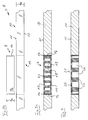
- the structure of a micro-slotted absorber element according to an embodiment of FIG. 5 is in the Fig. 6a outlined.
- the rectangular cross-section rods 36 are, for example, 200 mm long and have a square cross-section of 20 ⁇ 20 mm in the end regions 38.
- a 0.2 mm deep groove is ground on one side, so that the micro-gaps 31 result with appropriate alignment of the rods by gluing the end regions 38.
- the end regions are only a few mm long, so that the illustrated absorber plate with a gap width of 0.2 mm has an acoustically effective open area of approximately 10% with respect to the first surface.
- the central areas can also be provided with two or more grooves, so that the 1.8 mm wide webs 37 form two or more micro-gaps and are supported between these two or more times.
- FIGS. 7 and 8 Further embodiments of absorbers with micro-columns are shown, in which in rectangular cross-section rods 39 with a height of 2.0 mm and a width of 1.8 mm to absorber plates with an area of 200 x 200 mm, 0.2 mm wide micro-columns 31 and an acoustically effective open area of about 10%.
- the spacer elements ensure that the sticks 39 can not approach more than the desired micro gap width of 0.2 mm during bonding.
- the narrow tolerance ranges with which the spacer elements can be produced, ensure that the gap widths also vary only within a narrow range and the absorption capacity of the absorber plates can be set precisely defined.
- the spacers are preferably made from materials that neither swell in the adhesive, nor show shrinkage during curing or drying of the adhesive.
- the rods 39 which do not differ in dimensioning from those of the previous example, inserted with their end portions in a comb 44 having a plurality of teeth 45 with a width of 0.2 mm, and thus the width of the to be created Micro gaps 31 pretends.
- the rods 39 can be glued or clamped directly into the comb 44. In this way, 100 sticks are combined to form an absorber plate, this again has an area of 200 x 200 mm and 99 micro gaps with a width of 0.2 mm, resulting in an acoustically effective area of approximately 10% relative to the first surface of the Add absorber plate.
- narrow gaps with widths in the range of 0.05 to 0.3 mm, preferably 0.2 mm have proven to be advantageous.
- the narrow column widths of less than 0.3 mm can be achieved according to further advantageous embodiments of the invention by additive methods, such as the offset superimposition of two inserts with gap widths of more than 0.3 mm.
- the column width can be reduced in subsequent process steps, for example by immersion in clearcoat.
- the absorption power alpha (y-axis) is plotted against the frequency (x-axis) in the range of 62.5 to 4000 Hz.
- the very broad absorption spectrum of an absorber sandwiched from two absorber plates with microcolumns has two absorption maxima.
- the columns of the first absorber plate with a thickness of 1 mm are 0.2 mm wide and have a resonance length (as a Helmholtz resonator) of 12 mm. They form an acoustically effective open area of 10% in the absorber plate.
- the columns of the second, 5 mm thick absorber plate are also 0.2 mm wide, have a resonance length of 45 mm and form in the second absorber plate an acoustically effective open area of 10%.
- the bars are each 1.8 mm wide.
- the two absorption maxima are at about 1000 and 3500 Hz.
- the measured acoustic element has an acoustically effective open area of 5% and absorbs with a broad absorption spectrum whose maximum lies in the region of about 800 Hz at 1.
- the inventive absorption elements leave the manufacturer a maximum of creative freedom. Both the type of absorber, as well as their arrangement, as well as the shape and design of the absorber inserts can be varied within wide ranges.
- the transparent and / or translucent absorbers are combined with lighting means in order to produce lighting effects in addition to the sound absorption.
- Glass absorber inserts are ideally suited to set lighting accents in the acoustic element in combination with LEDs, light guides or other light sources.
- the bulbs can be mounted such that they do not adversely affect the absorber performance.
Landscapes
- Physics & Mathematics (AREA)
- Acoustics & Sound (AREA)
- Engineering & Computer Science (AREA)
- Architecture (AREA)
- Civil Engineering (AREA)
- Electromagnetism (AREA)
- Multimedia (AREA)
- Structural Engineering (AREA)
- Soundproofing, Sound Blocking, And Sound Damping (AREA)
- Surgical Instruments (AREA)
- Transducers For Ultrasonic Waves (AREA)
- Audible-Bandwidth Dynamoelectric Transducers Other Than Pickups (AREA)
- Building Environments (AREA)
Applications Claiming Priority (1)
| Application Number | Priority Date | Filing Date | Title |
|---|---|---|---|
| CH01128/07A CH700728B1 (de) | 2007-07-13 | 2007-07-13 | Akustikelemente. |
Publications (2)
| Publication Number | Publication Date |
|---|---|
| EP2015291A1 true EP2015291A1 (fr) | 2009-01-14 |
| EP2015291B1 EP2015291B1 (fr) | 2010-11-17 |
Family
ID=39810186
Family Applications (1)
| Application Number | Title | Priority Date | Filing Date |
|---|---|---|---|
| EP08010014A Not-in-force EP2015291B1 (fr) | 2007-07-13 | 2008-06-02 | Eléments acoustiques |
Country Status (4)
| Country | Link |
|---|---|
| EP (1) | EP2015291B1 (fr) |
| AT (1) | ATE488837T1 (fr) |
| CH (1) | CH700728B1 (fr) |
| DE (1) | DE502008001803D1 (fr) |
Cited By (9)
| Publication number | Priority date | Publication date | Assignee | Title |
|---|---|---|---|---|
| DE102011012222A1 (de) | 2011-02-22 | 2012-08-23 | Sächsisches Textilforschungsinstitut e.V. | Textiler Schallabsorber |
| EP2540926A1 (fr) | 2011-07-01 | 2013-01-02 | Akusik & Innovation GmbH | Elément à absorption acoustique et son procédé de fabrication |
| EP2251497A3 (fr) * | 2009-05-04 | 2013-05-15 | Albers & Co. | Eléments en verre flexibles |
| WO2013159240A1 (fr) | 2012-04-26 | 2013-10-31 | Akustik & Raum Ag | Élément d'absorption acoustique |
| WO2013124069A3 (fr) * | 2012-02-23 | 2013-11-14 | Noisetech Hb | Absorbant phonique |
| WO2015167342A1 (fr) * | 2014-04-29 | 2015-11-05 | Deamp As | Matériau insonorisant, son procédé de production et dispositif de découpe d'ouvertures dans le matériau insonorisant |
| CN108780637A (zh) * | 2016-02-08 | 2018-11-09 | 巴黎第十大学 | 声吸收器、吸声壁以及设计和生产方法 |
| CN109405262A (zh) * | 2018-12-14 | 2019-03-01 | 中国船舶重工集团公司第七〇四研究所 | 管路噪声主动控制系统、主被动复合管路消声器 |
| DE102023132980A1 (de) * | 2023-11-27 | 2025-05-28 | Lindner Se | Schallabsorber mit mehrteiligem Absorberkörper |
Families Citing this family (2)
| Publication number | Priority date | Publication date | Assignee | Title |
|---|---|---|---|---|
| DE102012000412A1 (de) | 2012-01-12 | 2013-07-18 | Fraunhofer-Gesellschaft zur Förderung der angewandten Forschung e.V. | Strahlungsemittierendes Bauteil mit akustisch einstellbarer Wirkung und Verfahren zur Herstellung derselben |
| IT202200006530A1 (it) * | 2022-04-01 | 2023-10-01 | Unifor Spa | Pannello per una parete divisoria opaca ad elevato isolamento acustico, e parete divisoria opaca comprendente detto pannello |
Citations (8)
| Publication number | Priority date | Publication date | Assignee | Title |
|---|---|---|---|---|
| BE647012A (fr) * | 1963-04-24 | 1964-08-17 | ||
| DE2434768A1 (de) * | 1974-07-19 | 1976-02-05 | Gruenzweig Hartmann Glasfaser | Akustikplatte und verfahren zur herstellung |
| DE4315759C1 (de) | 1993-05-11 | 1994-05-05 | Fraunhofer Ges Forschung | Schallabsorbierendes Glas- oder transparentes Kunstglasbauteil |
| DE10151474A1 (de) * | 2000-10-18 | 2002-05-02 | Fraunhofer Ges Forschung | Schallabsorber mit streifenförmiger schalldichter Abdeckung |
| EP1428656A1 (fr) * | 2002-12-09 | 2004-06-16 | Rieter Technologies A.G. | Elément d'habillage multicouche ultra-léger |
| WO2006021605A1 (fr) * | 2004-06-03 | 2006-03-02 | Consejo Superior De Investigaciones Científicas | Unites d'insertion microperforees destinees a etre utilisees en tant qu'absorbants acoustiques |
| EP1876308A2 (fr) | 2006-07-07 | 2008-01-09 | Akustik & Raum AG | Dispositif absorbant le bruit |
| EP1950357A1 (fr) | 2007-01-29 | 2008-07-30 | Akustik & Raum AG | Eléments acoustiques |
-
2007
- 2007-07-13 CH CH01128/07A patent/CH700728B1/de not_active IP Right Cessation
-
2008
- 2008-06-02 DE DE502008001803T patent/DE502008001803D1/de active Active
- 2008-06-02 AT AT08010014T patent/ATE488837T1/de active
- 2008-06-02 EP EP08010014A patent/EP2015291B1/fr not_active Not-in-force
Patent Citations (8)
| Publication number | Priority date | Publication date | Assignee | Title |
|---|---|---|---|---|
| BE647012A (fr) * | 1963-04-24 | 1964-08-17 | ||
| DE2434768A1 (de) * | 1974-07-19 | 1976-02-05 | Gruenzweig Hartmann Glasfaser | Akustikplatte und verfahren zur herstellung |
| DE4315759C1 (de) | 1993-05-11 | 1994-05-05 | Fraunhofer Ges Forschung | Schallabsorbierendes Glas- oder transparentes Kunstglasbauteil |
| DE10151474A1 (de) * | 2000-10-18 | 2002-05-02 | Fraunhofer Ges Forschung | Schallabsorber mit streifenförmiger schalldichter Abdeckung |
| EP1428656A1 (fr) * | 2002-12-09 | 2004-06-16 | Rieter Technologies A.G. | Elément d'habillage multicouche ultra-léger |
| WO2006021605A1 (fr) * | 2004-06-03 | 2006-03-02 | Consejo Superior De Investigaciones Científicas | Unites d'insertion microperforees destinees a etre utilisees en tant qu'absorbants acoustiques |
| EP1876308A2 (fr) | 2006-07-07 | 2008-01-09 | Akustik & Raum AG | Dispositif absorbant le bruit |
| EP1950357A1 (fr) | 2007-01-29 | 2008-07-30 | Akustik & Raum AG | Eléments acoustiques |
Non-Patent Citations (3)
| Title |
|---|
| D.-Y. MAA, SCIENTIA SINICA, vol. 18, no. 1, 1975 |
| FUCHAS HELMUT AND XUEQIN ZHA: "Micro-perforated structures as sound absorbers : A review and outlook", ACUSTICA UNITED WITH ACTA ACUSTICA, S. HIRZEL VERLAG, STUTTGART, DE, vol. 92, no. 1, 1 January 2006 (2006-01-01), pages 139 - 146, XP009106599, ISSN: 1610-1928 * |
| PFRETZSCHNER ET AL: "Microperforated insertion units: An alternative strategy to design microperforated panels", APPLIED ACOUSTICS, ELSEVIER PUBLISHING, GB, vol. 67, no. 1, 1 January 2006 (2006-01-01), pages 62 - 73, XP005117938, ISSN: 0003-682X * |
Cited By (10)
| Publication number | Priority date | Publication date | Assignee | Title |
|---|---|---|---|---|
| EP2251497A3 (fr) * | 2009-05-04 | 2013-05-15 | Albers & Co. | Eléments en verre flexibles |
| DE102011012222A1 (de) | 2011-02-22 | 2012-08-23 | Sächsisches Textilforschungsinstitut e.V. | Textiler Schallabsorber |
| DE102011012222B4 (de) * | 2011-02-22 | 2014-01-16 | Sächsisches Textilforschungsinstitut e.V. | Textiler Schallabsorber |
| EP2540926A1 (fr) | 2011-07-01 | 2013-01-02 | Akusik & Innovation GmbH | Elément à absorption acoustique et son procédé de fabrication |
| WO2013124069A3 (fr) * | 2012-02-23 | 2013-11-14 | Noisetech Hb | Absorbant phonique |
| WO2013159240A1 (fr) | 2012-04-26 | 2013-10-31 | Akustik & Raum Ag | Élément d'absorption acoustique |
| WO2015167342A1 (fr) * | 2014-04-29 | 2015-11-05 | Deamp As | Matériau insonorisant, son procédé de production et dispositif de découpe d'ouvertures dans le matériau insonorisant |
| CN108780637A (zh) * | 2016-02-08 | 2018-11-09 | 巴黎第十大学 | 声吸收器、吸声壁以及设计和生产方法 |
| CN109405262A (zh) * | 2018-12-14 | 2019-03-01 | 中国船舶重工集团公司第七〇四研究所 | 管路噪声主动控制系统、主被动复合管路消声器 |
| DE102023132980A1 (de) * | 2023-11-27 | 2025-05-28 | Lindner Se | Schallabsorber mit mehrteiligem Absorberkörper |
Also Published As
| Publication number | Publication date |
|---|---|
| EP2015291B1 (fr) | 2010-11-17 |
| ATE488837T1 (de) | 2010-12-15 |
| DE502008001803D1 (de) | 2010-12-30 |
| CH700728B1 (de) | 2010-10-15 |
Similar Documents
| Publication | Publication Date | Title |
|---|---|---|
| EP2015291B1 (fr) | Eléments acoustiques | |
| EP1950357B1 (fr) | Eléments acoustiques | |
| EP2540926B1 (fr) | Elément absorbant acoustique et son procédé de fabrication | |
| EP2937483B1 (fr) | Panneau de construction, en particulier dalle de plafond ou murale | |
| EP1815460B1 (fr) | Couche de revetement, panneau a proprietes d'absorption acoustique et procede pour les produire | |
| WO2000014353A1 (fr) | Element sous forme de plaque | |
| DE19861016C2 (de) | Strukturierte Formkörper zur Schallabsorption | |
| EP2841660A1 (fr) | Élément d'absorption acoustique | |
| DE10214778A1 (de) | Schallabsorbierendes Paneel | |
| DE9116233U1 (de) | Schallabsorbierende Verglasung | |
| EP2579248A2 (fr) | Procédé de fabrication d'une plaque d'insonorisation à deux ou trois couches et plaque d'insonorisation associée | |
| CH706392A2 (de) | Schallabsorbierendes Element. | |
| EP0992636A2 (fr) | Panneau isolant acoustique pour l'aménagement intérieur | |
| DE102022116863A1 (de) | Plattenförmiges Element für die Wand- und Deckenverkleidung | |
| AT405069B (de) | Akustikplatte sowie verfahren zur herstellung derselben | |
| EP2251497B1 (fr) | Eléments en verre flexibles | |
| EP1146178A2 (fr) | Elément de construction pour murs, planchers et plafonds à large spectre d'absorbtion sonore | |
| DE19957317C2 (de) | Verfahren zur Anbringung von Sollbruchkanten an einem Werkstück | |
| CH698892B1 (de) | Akustikelemente. | |
| EP1411179B1 (fr) | Panneau d'insonorisation | |
| EP2575127A1 (fr) | Elément d'absorption acoustique | |
| CH713133B1 (de) | Schallabsorbierendes Element. | |
| EP1406792B1 (fr) | Element d'isolation phonique | |
| DE20112669U1 (de) | Schallabsorbierendes Paneel | |
| WO2006119964A2 (fr) | Composant absorbant le son |
Legal Events
| Date | Code | Title | Description |
|---|---|---|---|
| PUAI | Public reference made under article 153(3) epc to a published international application that has entered the european phase |
Free format text: ORIGINAL CODE: 0009012 |
|
| AK | Designated contracting states |
Kind code of ref document: A1 Designated state(s): AT BE BG CH CY CZ DE DK EE ES FI FR GB GR HR HU IE IS IT LI LT LU LV MC MT NL NO PL PT RO SE SI SK TR |
|
| AX | Request for extension of the european patent |
Extension state: AL BA MK RS |
|
| 17P | Request for examination filed |
Effective date: 20090714 |
|
| 17Q | First examination report despatched |
Effective date: 20090805 |
|
| AKX | Designation fees paid |
Designated state(s): AT BE BG CH CY CZ DE DK EE ES FI FR GB GR HR HU IE IS IT LI LT LU LV MC MT NL NO PL PT RO SE SI SK TR |
|
| RAP1 | Party data changed (applicant data changed or rights of an application transferred) |
Owner name: ALBERS & CO. |
|
| GRAP | Despatch of communication of intention to grant a patent |
Free format text: ORIGINAL CODE: EPIDOSNIGR1 |
|
| GRAS | Grant fee paid |
Free format text: ORIGINAL CODE: EPIDOSNIGR3 |
|
| GRAA | (expected) grant |
Free format text: ORIGINAL CODE: 0009210 |
|
| AK | Designated contracting states |
Kind code of ref document: B1 Designated state(s): AT BE BG CH CY CZ DE DK EE ES FI FR GB GR HR HU IE IS IT LI LT LU LV MC MT NL NO PL PT RO SE SI SK TR |
|
| REG | Reference to a national code |
Ref country code: GB Ref legal event code: FG4D Free format text: NOT ENGLISH |
|
| REG | Reference to a national code |
Ref country code: CH Ref legal event code: EP |
|
| REG | Reference to a national code |
Ref country code: CH Ref legal event code: NV Representative=s name: RENTSCH & PARTNER |
|
| REG | Reference to a national code |
Ref country code: IE Ref legal event code: FG4D |
|
| REF | Corresponds to: |
Ref document number: 502008001803 Country of ref document: DE Date of ref document: 20101230 Kind code of ref document: P |
|
| REG | Reference to a national code |
Ref country code: NL Ref legal event code: VDEP Effective date: 20101117 |
|
| LTIE | Lt: invalidation of european patent or patent extension |
Effective date: 20101117 |
|
| PG25 | Lapsed in a contracting state [announced via postgrant information from national office to epo] |
Ref country code: NO Free format text: LAPSE BECAUSE OF FAILURE TO SUBMIT A TRANSLATION OF THE DESCRIPTION OR TO PAY THE FEE WITHIN THE PRESCRIBED TIME-LIMIT Effective date: 20110217 Ref country code: LT Free format text: LAPSE BECAUSE OF FAILURE TO SUBMIT A TRANSLATION OF THE DESCRIPTION OR TO PAY THE FEE WITHIN THE PRESCRIBED TIME-LIMIT Effective date: 20101117 |
|
| PG25 | Lapsed in a contracting state [announced via postgrant information from national office to epo] |
Ref country code: HR Free format text: LAPSE BECAUSE OF FAILURE TO SUBMIT A TRANSLATION OF THE DESCRIPTION OR TO PAY THE FEE WITHIN THE PRESCRIBED TIME-LIMIT Effective date: 20101117 Ref country code: NL Free format text: LAPSE BECAUSE OF FAILURE TO SUBMIT A TRANSLATION OF THE DESCRIPTION OR TO PAY THE FEE WITHIN THE PRESCRIBED TIME-LIMIT Effective date: 20101117 Ref country code: SE Free format text: LAPSE BECAUSE OF FAILURE TO SUBMIT A TRANSLATION OF THE DESCRIPTION OR TO PAY THE FEE WITHIN THE PRESCRIBED TIME-LIMIT Effective date: 20101117 Ref country code: BG Free format text: LAPSE BECAUSE OF FAILURE TO SUBMIT A TRANSLATION OF THE DESCRIPTION OR TO PAY THE FEE WITHIN THE PRESCRIBED TIME-LIMIT Effective date: 20110217 Ref country code: PT Free format text: LAPSE BECAUSE OF FAILURE TO SUBMIT A TRANSLATION OF THE DESCRIPTION OR TO PAY THE FEE WITHIN THE PRESCRIBED TIME-LIMIT Effective date: 20110317 Ref country code: SI Free format text: LAPSE BECAUSE OF FAILURE TO SUBMIT A TRANSLATION OF THE DESCRIPTION OR TO PAY THE FEE WITHIN THE PRESCRIBED TIME-LIMIT Effective date: 20101117 Ref country code: IS Free format text: LAPSE BECAUSE OF FAILURE TO SUBMIT A TRANSLATION OF THE DESCRIPTION OR TO PAY THE FEE WITHIN THE PRESCRIBED TIME-LIMIT Effective date: 20110317 Ref country code: FI Free format text: LAPSE BECAUSE OF FAILURE TO SUBMIT A TRANSLATION OF THE DESCRIPTION OR TO PAY THE FEE WITHIN THE PRESCRIBED TIME-LIMIT Effective date: 20101117 Ref country code: LV Free format text: LAPSE BECAUSE OF FAILURE TO SUBMIT A TRANSLATION OF THE DESCRIPTION OR TO PAY THE FEE WITHIN THE PRESCRIBED TIME-LIMIT Effective date: 20101117 Ref country code: CY Free format text: LAPSE BECAUSE OF FAILURE TO SUBMIT A TRANSLATION OF THE DESCRIPTION OR TO PAY THE FEE WITHIN THE PRESCRIBED TIME-LIMIT Effective date: 20101117 |
|
| REG | Reference to a national code |
Ref country code: IE Ref legal event code: FD4D |
|
| PG25 | Lapsed in a contracting state [announced via postgrant information from national office to epo] |
Ref country code: GR Free format text: LAPSE BECAUSE OF FAILURE TO SUBMIT A TRANSLATION OF THE DESCRIPTION OR TO PAY THE FEE WITHIN THE PRESCRIBED TIME-LIMIT Effective date: 20110218 |
|
| REG | Reference to a national code |
Ref country code: CH Ref legal event code: PFA Owner name: ALBERS & CO. Free format text: ALBERS & CO.#SCHANZENGASSE 14 POSTFACH 2016#8022 ZUERICH (CH) -TRANSFER TO- ALBERS & CO.#SCHANZENGASSE 14 POSTFACH 2016#8022 ZUERICH (CH) |
|
| PG25 | Lapsed in a contracting state [announced via postgrant information from national office to epo] |
Ref country code: CZ Free format text: LAPSE BECAUSE OF FAILURE TO SUBMIT A TRANSLATION OF THE DESCRIPTION OR TO PAY THE FEE WITHIN THE PRESCRIBED TIME-LIMIT Effective date: 20101117 Ref country code: IE Free format text: LAPSE BECAUSE OF FAILURE TO SUBMIT A TRANSLATION OF THE DESCRIPTION OR TO PAY THE FEE WITHIN THE PRESCRIBED TIME-LIMIT Effective date: 20101117 Ref country code: EE Free format text: LAPSE BECAUSE OF FAILURE TO SUBMIT A TRANSLATION OF THE DESCRIPTION OR TO PAY THE FEE WITHIN THE PRESCRIBED TIME-LIMIT Effective date: 20101117 Ref country code: ES Free format text: LAPSE BECAUSE OF FAILURE TO SUBMIT A TRANSLATION OF THE DESCRIPTION OR TO PAY THE FEE WITHIN THE PRESCRIBED TIME-LIMIT Effective date: 20110228 |
|
| PG25 | Lapsed in a contracting state [announced via postgrant information from national office to epo] |
Ref country code: RO Free format text: LAPSE BECAUSE OF FAILURE TO SUBMIT A TRANSLATION OF THE DESCRIPTION OR TO PAY THE FEE WITHIN THE PRESCRIBED TIME-LIMIT Effective date: 20101117 Ref country code: PL Free format text: LAPSE BECAUSE OF FAILURE TO SUBMIT A TRANSLATION OF THE DESCRIPTION OR TO PAY THE FEE WITHIN THE PRESCRIBED TIME-LIMIT Effective date: 20101117 Ref country code: DK Free format text: LAPSE BECAUSE OF FAILURE TO SUBMIT A TRANSLATION OF THE DESCRIPTION OR TO PAY THE FEE WITHIN THE PRESCRIBED TIME-LIMIT Effective date: 20101117 Ref country code: SK Free format text: LAPSE BECAUSE OF FAILURE TO SUBMIT A TRANSLATION OF THE DESCRIPTION OR TO PAY THE FEE WITHIN THE PRESCRIBED TIME-LIMIT Effective date: 20101117 |
|
| PLBE | No opposition filed within time limit |
Free format text: ORIGINAL CODE: 0009261 |
|
| STAA | Information on the status of an ep patent application or granted ep patent |
Free format text: STATUS: NO OPPOSITION FILED WITHIN TIME LIMIT |
|
| 26N | No opposition filed |
Effective date: 20110818 |
|
| REG | Reference to a national code |
Ref country code: DE Ref legal event code: R097 Ref document number: 502008001803 Country of ref document: DE Effective date: 20110818 |
|
| PG25 | Lapsed in a contracting state [announced via postgrant information from national office to epo] |
Ref country code: MT Free format text: LAPSE BECAUSE OF FAILURE TO SUBMIT A TRANSLATION OF THE DESCRIPTION OR TO PAY THE FEE WITHIN THE PRESCRIBED TIME-LIMIT Effective date: 20101117 Ref country code: IT Free format text: LAPSE BECAUSE OF FAILURE TO SUBMIT A TRANSLATION OF THE DESCRIPTION OR TO PAY THE FEE WITHIN THE PRESCRIBED TIME-LIMIT Effective date: 20101117 |
|
| BERE | Be: lapsed |
Owner name: ALBERS & CO. Effective date: 20110630 |
|
| PG25 | Lapsed in a contracting state [announced via postgrant information from national office to epo] |
Ref country code: BE Free format text: LAPSE BECAUSE OF NON-PAYMENT OF DUE FEES Effective date: 20110630 |
|
| PGFP | Annual fee paid to national office [announced via postgrant information from national office to epo] |
Ref country code: GB Payment date: 20120720 Year of fee payment: 5 |
|
| PG25 | Lapsed in a contracting state [announced via postgrant information from national office to epo] |
Ref country code: MC Free format text: LAPSE BECAUSE OF NON-PAYMENT OF DUE FEES Effective date: 20110630 |
|
| PGFP | Annual fee paid to national office [announced via postgrant information from national office to epo] |
Ref country code: LU Payment date: 20130621 Year of fee payment: 6 |
|
| PGFP | Annual fee paid to national office [announced via postgrant information from national office to epo] |
Ref country code: FR Payment date: 20130703 Year of fee payment: 6 |
|
| PG25 | Lapsed in a contracting state [announced via postgrant information from national office to epo] |
Ref country code: TR Free format text: LAPSE BECAUSE OF FAILURE TO SUBMIT A TRANSLATION OF THE DESCRIPTION OR TO PAY THE FEE WITHIN THE PRESCRIBED TIME-LIMIT Effective date: 20101117 |
|
| PG25 | Lapsed in a contracting state [announced via postgrant information from national office to epo] |
Ref country code: HU Free format text: LAPSE BECAUSE OF FAILURE TO SUBMIT A TRANSLATION OF THE DESCRIPTION OR TO PAY THE FEE WITHIN THE PRESCRIBED TIME-LIMIT Effective date: 20101117 |
|
| GBPC | Gb: european patent ceased through non-payment of renewal fee |
Effective date: 20130602 |
|
| PG25 | Lapsed in a contracting state [announced via postgrant information from national office to epo] |
Ref country code: GB Free format text: LAPSE BECAUSE OF NON-PAYMENT OF DUE FEES Effective date: 20130602 |
|
| PG25 | Lapsed in a contracting state [announced via postgrant information from national office to epo] |
Ref country code: LU Free format text: LAPSE BECAUSE OF NON-PAYMENT OF DUE FEES Effective date: 20140602 |
|
| REG | Reference to a national code |
Ref country code: AT Ref legal event code: MM01 Ref document number: 488837 Country of ref document: AT Kind code of ref document: T Effective date: 20140602 |
|
| REG | Reference to a national code |
Ref country code: FR Ref legal event code: ST Effective date: 20150227 |
|
| PG25 | Lapsed in a contracting state [announced via postgrant information from national office to epo] |
Ref country code: AT Free format text: LAPSE BECAUSE OF NON-PAYMENT OF DUE FEES Effective date: 20140602 Ref country code: FR Free format text: LAPSE BECAUSE OF NON-PAYMENT OF DUE FEES Effective date: 20140630 |
|
| REG | Reference to a national code |
Ref country code: CH Ref legal event code: PCAR Free format text: NEW ADDRESS: BELLERIVESTRASSE 203 POSTFACH, 8034 ZUERICH (CH) |
|
| PGFP | Annual fee paid to national office [announced via postgrant information from national office to epo] |
Ref country code: DE Payment date: 20200618 Year of fee payment: 13 Ref country code: CH Payment date: 20200618 Year of fee payment: 13 |
|
| REG | Reference to a national code |
Ref country code: DE Ref legal event code: R119 Ref document number: 502008001803 Country of ref document: DE |
|
| REG | Reference to a national code |
Ref country code: CH Ref legal event code: PL |
|
| PG25 | Lapsed in a contracting state [announced via postgrant information from national office to epo] |
Ref country code: LI Free format text: LAPSE BECAUSE OF NON-PAYMENT OF DUE FEES Effective date: 20210630 Ref country code: DE Free format text: LAPSE BECAUSE OF NON-PAYMENT OF DUE FEES Effective date: 20220101 Ref country code: CH Free format text: LAPSE BECAUSE OF NON-PAYMENT OF DUE FEES Effective date: 20210630 |