EP2015369A2 - Structure de support destinée à soutenir des panneaux solaires plats - Google Patents
Structure de support destinée à soutenir des panneaux solaires plats Download PDFInfo
- Publication number
- EP2015369A2 EP2015369A2 EP08007136A EP08007136A EP2015369A2 EP 2015369 A2 EP2015369 A2 EP 2015369A2 EP 08007136 A EP08007136 A EP 08007136A EP 08007136 A EP08007136 A EP 08007136A EP 2015369 A2 EP2015369 A2 EP 2015369A2
- Authority
- EP
- European Patent Office
- Prior art keywords
- support
- mast
- storage rack
- central
- rack according
- Prior art date
- Legal status (The legal status is an assumption and is not a legal conclusion. Google has not performed a legal analysis and makes no representation as to the accuracy of the status listed.)
- Granted
Links
Images


Classifications
-
- H—ELECTRICITY
- H02—GENERATION; CONVERSION OR DISTRIBUTION OF ELECTRIC POWER
- H02S—GENERATION OF ELECTRIC POWER BY CONVERSION OF INFRARED RADIATION, VISIBLE LIGHT OR ULTRAVIOLET LIGHT, e.g. USING PHOTOVOLTAIC [PV] MODULES
- H02S20/00—Supporting structures for PV modules
-
- F—MECHANICAL ENGINEERING; LIGHTING; HEATING; WEAPONS; BLASTING
- F24—HEATING; RANGES; VENTILATING
- F24S—SOLAR HEAT COLLECTORS; SOLAR HEAT SYSTEMS
- F24S25/00—Arrangement of stationary mountings or supports for solar heat collector modules
- F24S25/10—Arrangement of stationary mountings or supports for solar heat collector modules extending in directions away from a supporting surface
- F24S25/12—Arrangement of stationary mountings or supports for solar heat collector modules extending in directions away from a supporting surface using posts in combination with upper profiles
-
- F—MECHANICAL ENGINEERING; LIGHTING; HEATING; WEAPONS; BLASTING
- F24—HEATING; RANGES; VENTILATING
- F24S—SOLAR HEAT COLLECTORS; SOLAR HEAT SYSTEMS
- F24S30/00—Arrangements for moving or orienting solar heat collector modules
- F24S30/40—Arrangements for moving or orienting solar heat collector modules for rotary movement
- F24S30/45—Arrangements for moving or orienting solar heat collector modules for rotary movement with two rotation axes
- F24S30/452—Vertical primary axis
-
- H—ELECTRICITY
- H02—GENERATION; CONVERSION OR DISTRIBUTION OF ELECTRIC POWER
- H02S—GENERATION OF ELECTRIC POWER BY CONVERSION OF INFRARED RADIATION, VISIBLE LIGHT OR ULTRAVIOLET LIGHT, e.g. USING PHOTOVOLTAIC [PV] MODULES
- H02S20/00—Supporting structures for PV modules
- H02S20/30—Supporting structures being movable or adjustable, e.g. for angle adjustment
-
- F—MECHANICAL ENGINEERING; LIGHTING; HEATING; WEAPONS; BLASTING
- F24—HEATING; RANGES; VENTILATING
- F24S—SOLAR HEAT COLLECTORS; SOLAR HEAT SYSTEMS
- F24S30/00—Arrangements for moving or orienting solar heat collector modules
- F24S2030/10—Special components
- F24S2030/11—Driving means
-
- F—MECHANICAL ENGINEERING; LIGHTING; HEATING; WEAPONS; BLASTING
- F24—HEATING; RANGES; VENTILATING
- F24S—SOLAR HEAT COLLECTORS; SOLAR HEAT SYSTEMS
- F24S30/00—Arrangements for moving or orienting solar heat collector modules
- F24S2030/10—Special components
- F24S2030/15—Bearings
-
- F—MECHANICAL ENGINEERING; LIGHTING; HEATING; WEAPONS; BLASTING
- F24—HEATING; RANGES; VENTILATING
- F24S—SOLAR HEAT COLLECTORS; SOLAR HEAT SYSTEMS
- F24S25/00—Arrangement of stationary mountings or supports for solar heat collector modules
- F24S25/10—Arrangement of stationary mountings or supports for solar heat collector modules extending in directions away from a supporting surface
- F24S25/13—Profile arrangements, e.g. trusses
-
- Y—GENERAL TAGGING OF NEW TECHNOLOGICAL DEVELOPMENTS; GENERAL TAGGING OF CROSS-SECTIONAL TECHNOLOGIES SPANNING OVER SEVERAL SECTIONS OF THE IPC; TECHNICAL SUBJECTS COVERED BY FORMER USPC CROSS-REFERENCE ART COLLECTIONS [XRACs] AND DIGESTS
- Y02—TECHNOLOGIES OR APPLICATIONS FOR MITIGATION OR ADAPTATION AGAINST CLIMATE CHANGE
- Y02E—REDUCTION OF GREENHOUSE GAS [GHG] EMISSIONS, RELATED TO ENERGY GENERATION, TRANSMISSION OR DISTRIBUTION
- Y02E10/00—Energy generation through renewable energy sources
- Y02E10/40—Solar thermal energy, e.g. solar towers
- Y02E10/47—Mountings or tracking
-
- Y—GENERAL TAGGING OF NEW TECHNOLOGICAL DEVELOPMENTS; GENERAL TAGGING OF CROSS-SECTIONAL TECHNOLOGIES SPANNING OVER SEVERAL SECTIONS OF THE IPC; TECHNICAL SUBJECTS COVERED BY FORMER USPC CROSS-REFERENCE ART COLLECTIONS [XRACs] AND DIGESTS
- Y02—TECHNOLOGIES OR APPLICATIONS FOR MITIGATION OR ADAPTATION AGAINST CLIMATE CHANGE
- Y02E—REDUCTION OF GREENHOUSE GAS [GHG] EMISSIONS, RELATED TO ENERGY GENERATION, TRANSMISSION OR DISTRIBUTION
- Y02E10/00—Energy generation through renewable energy sources
- Y02E10/50—Photovoltaic [PV] energy
Definitions
- the invention relates to a storage rack for supporting flat solar panels, with a mounted in its mounted position substantially vertical and storable at its lower end in the ground or at a fixed anchoring point support mast on which the resting on a flat panel holder solar panels by means of a support structure and the Azimuth tracking are rotatable about the mast axis.
- Such storage racks are known in various embodiments, with a tracking of the elevation angle of the solar panels, so tracking the angle of the solar panels relative to the horizontal, is also possible.
- the support structure in some known models consists of struts that engage the back of the panel mount.
- the storage rack consists essentially only of the vertical support mast itself, which acts approximately centrally on the back of the respective panel mount and the same accordingly only supported at this more or less punctiform point. Even with the known constructions that use struts, the points of attack of these struts are in the central region at the back of the panel mount, which has the disadvantage that these counting of the prior art storage racks and panel mounts can record a limited overall wind and snow load ,
- the support structures are composed of struts, is that these support structures are at least partially welded together at the place of manufacture due to their relatively complicated design and thus represent bulky goods in transit. Therefore, the number of these storage racks, which can be accommodated in a transport container or similar means of transport, is relatively limited.
- the aim of the invention is to provide a storage rack of the type mentioned above with a support structure for the panel mount, which withstands high wind and snow loads and can still be transported due to its relatively simple structure in the disassembled state to the site.
- This invention consisting of three central struts support triangle, which is attached to the upper end of the mast at a central support member, thereby ensuring that the generated in the supported areas of the panel mount wind or snow loads are derived symmetrically in the support structure according to the invention, since the support triangle symmetrical arranged to the mast axis in a substantially horizontal plane and is supported at all its points of the triangle by supporting struts which extend obliquely down to a support point at the lower end of the mast.
- the support triangle attached to the central support part with the support struts running obliquely to the support point at the lower end of the mast forms a kind of substructure which symmetrically receives the loads generated by the panel support via the struts or support elements acting on the back of this panel support and into the ground or derives in the stationary anchoring point of the support mast.
- tilting moments of the storage rack are reduced to a minimum and excessive loads of the same excluded.
- the elevation angle can be set both manually and by a servomotor. Both possibilities are also feasible in a storage rack according to the invention.
- the appended claim 9 indicates a contribution to the stability enhancement of a per se known panel mount, as e.g. can be used in a storage rack according to the invention.
- the support mast can be anchored axially rotatably at its lower end.
- This first possibility is based on the measures according to the attached claims 10 and 11.
- the support structure with the central support member is rotatable.
- This alternative is based on the features according to the appended claims 12 and 13, which characterize expedient and advantageous features for this purpose.
- additional support struts may be provided for additional support of the support point at the lower end of the mast, as claimed in the accompanying claim 14.
- the support point at the lower end of the mast can be carried out in this second alternative as a plate-shaped flange part, as claimed in claims 15 and 16.
- the subject matter of claim 20 ensures a quick and easy 'replacement of the bearing ring by the two half-shells of the plate-shaped flange part are separated from each other.
- a particularly suitable for an inventive storage rack 'training of the central support member is characterized in the claims 21 and 22, since the provided connecting flanges allow a quick and convenient attachment of the struts of the support structure.
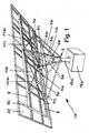
- FIG. 1 - 4 illustrated storage rack serves to support planar solar panels 12, which rest on a panel mount.
- This panel holder comprises a lower cross member 8 and an upper cross member 9, which extend in the assembled state at a mutual distance substantially horizontally over approximately the entire solar panel width.
- Both transverse beams 8 and 9 are secured together by a plurality of longitudinal members 10 which follow one another in the assembled state in the direction of the longitudinal extension of the transverse beams 8 and 9 at equal intervals.
- the panel support is reinforced by four additional reinforcing struts 11a-11d, of which two reinforcing struts 11a and 11b and 11c and 11d are arranged crosswise, respectively, to form a reinforcing cross.
- the storage rack further comprises a substantially vertical support mast 13, which is anchored at its lower end 13a to a fixed anchoring point 13b rotationally fixed.
- This support mast supports with the help of a support structure which in FIG. 1 denoted overall by the reference numeral 14, the panel mount already described on which the solar panels 12 rest.
- the support structure 14 comprises at the upper end of the mast a central support part 1, to which three in the assembled state in a plane substantially perpendicular to the mast axis plane and in this plane forming a support triangle central struts 6a - 6c are attached.
- two further support struts 3b and 3a are provided which extend between the front and rear sides of the central support part 1 and the support point 2 at the lower mast end 13a.
- the front support strut 3b is attached at its upper end to the central region of the lower cross member 8 of the panel holder and supports in this way from this area.
- the two lateral end portions of the cross member 8 are supported by two additional struts 4c and 4d, which are also secured in the respective end regions on the lower cross member 8 and extend obliquely downward to the support point 2 at the lower end of the mast 13a.
- FIGS. 1 and 4 How out Figures 2 and 3 can be seen for additional support of the support point 2 at the lower end of the mast 13a two holding struts 5a and 5b provided, which extend on both sides of the mast 13 between the central support part 1 and the support point 2 and whose respective ends are also fixed to the support part 1 and at the support point 2 ,
- These support struts 5a and 5b, the sake of clarity in the FIGS. 1 and 4 are omitted, supplement the substructure and contribute to their further stability.
- the support structure 14 further comprises for further support of the panel support a plurality of support elements extending between the upper cross member 9 and the hypotenuse of the support triangle forming central strut 6a.
- these support elements have a fixed length and represent over the substantially horizontal plane of Stütrdreieckes upstanding linear extensions of those three support struts 4a, 4b and 3a, which is between the hypotenuse of the support triangle, forming the central strut 6a and the Support point 2 extend at the bottom of the mast 13a.
- These three extensions are attached with their ends fixed to the upper cross member 9 of the panel holder and support the latter in their two upper lateral areas and upper middle area. In this way, the elevation angle of the solar panels 12 is fixed.
- the central support part 1 of the support structure 14 comprises a substantially rectangular plate-shaped base part. 1a, at the four side edges of the base part of one piece connecting flanges 1b - 1e are formed, which are angled relative to the plate plane and serve to fasten the struts of the support structure. Since in all figures, the fixed connections to the support structure 14 are realized by screw 26 with screws, nuts and washers of the same size, the central support member 1, as FIG. 10 also shows corresponding holes for these screw connections.
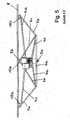
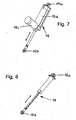
- FIG. 6 To achieve an adjustable elevation angle of the solar panels 12 are in accordance with the in the Figures 5 and 6 embodiment of the invention shown at the lower cross member 8 of the panel holder attacking struts of the support structure 14 hinged to this cross member at 15a, 15b and 15c. Further, as shown in FIG. 6 two telescopically extendable support members 16 and 17 are provided, which are articulated with their one ends 16b and 17b at the two ends of the hypotenuse of the support triangle forming the central strut 6a.
- each of the two support elements 16 and 17 may comprise a structural unit 19 each comprising a servomotor 19c and a tubular telescopic arrangement 19d which is in operative connection with the servomotor and which can be pulled out by it.
- Anlenkflansche 19a and 19b serve for articulation to the cross member 9 and the central Im
- the locking is realized here by bolts, not shown, which are passed through corresponding congruent holes in the two parts of the support strut.
- Corresponding Anlenkflansche bear the reference numerals 18a and 18b.
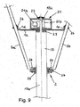
- the central support member 1 at the upper end of the mast and the support point 2 at the lower end of the mast 13a are axially freely rotatably mounted on rotatably anchored support mast 13.
- the central support part 1 has a central bore 1f ( FIG. 10 ) and is, as in FIG. 9 represented, pushed by means of this bore on a the upper mast end forming shaft journals 13c.
- the pivot bearing for the deferred support part 1 forms according to FIG. 9 here a plastic disc 23, which is also penetrated by the shaft journal 13c and which rests on a radial shoulder between the shaft journal 13c and the outer circumference of the support mast 13.
- a gear 21 b is further rotatably anchored, which with the drive screw 21 a of a total in FIG. 9
- the worm drive designated by the reference numeral 21 meshes.
- This worm drive is firmly connected to the central support part 1, so that upon rotation of the drive worm 21a, this worm drive together with the central support part 1 firmly connected thereto and the support structure held on the support part 14 performs a rotational movement about the gear wheel 21b. In this way, the supported by the support structure 14 solar panels 12 are tracked in the azimuth direction.
- An attached at the upper end of the shaft journal 13c retaining flange 22 prevents lifting of the attached to the central support members 1 worm drive 21 of the pivot bearing this support part forming plastic disc 23rd
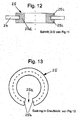
- FIG. 9 in conjunction with the FIGS. 11-13 shows, with respect to the support mast 13 rotatable support point 2 is designed as a plate-shaped flange portion 24 with a central bore 24a, which is the lower support mast end 13a receives and peripherally encloses with radial distance.
- This free distance is filled by a slidable on the edge of the bore 24a and serving as a pivot bearing for the flange 24 bearing ring 25 made of lubricious plastic.
- the bearing ring 25 has a U-shaped cross-section on with a substantially the thickness of the plate-shaped flange portion 24 corresponding inner width between the two legs 25c of this bearing ring.
- the demarcated from the free leg ends opening is located on the outer ring circumference, so that when deferred bearing ring 25 whose two legs extend on both sides of the side edges of the central bore 24a.
- the lower leg ends connecting yoke 25d ( FIG. 12 ) of the bearing ring 25 fills in this way the space between the inner edge of the central bore 24 a and outer circumference of the support mast 13.
- a nose 24b lying in the plane of the plate-shaped flange part 24 projects inwards in a substantially radial direction from the inner edge of the central bore 24a.
- the radial length of this nose is dimensioned such that this length at most equal to the radial distance between the outer mast circumference and inner edge of the central bore 24a.
- the material of the bearing ring 25 is segmented at 25a (FIG. FIG. 13 ) is cut away over a circumferential length which, viewed in the circumferential direction, substantially corresponds to the width of the projecting nose 24b. In this way, the pushed onto the edge of the bore bearing ring 25 can be rotatably held by the nose by abutting the wegberichte segment limiting end surfaces 25b of the bearing ring 25 at the side edges of this nose.
- the bearing ring 25 must be replaced once, a faster and more convenient ring exchange is preferably ensured if the plate-shaped flange 24 is formed in two parts and consists of two not shown fastened together half shells, which can be placed on the outer circumference of the support mast 13 and firmly connected are.
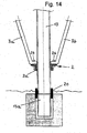
- the support mast 13 is held against rotation and for azimuth tracking contrast, the support structure 14 is rotated together with the central support member 1 and the support point 2 at the lower end of the mast 13a, alternatively, the support mast 13 itself be rotatably mounted.
- the support structure 14 with the central support member 1 and the lower support point 2 rotatably connected to the support mast.
- FIG. 14 shows, in which the lower pole end 13a is rotatably supported in a rotary bearing 20.
- the support point 2 is also formed here as a flange, but in contrast to the above-discussed embodiments here via an axial collar 2a and a screw is firmly connected to the support mast. Also in this case, the downwardly extending struts of the support structure 14 are connected by corresponding screw 26 with the supporting part 2 forming flange.
- the material for the support structure 14 galvanized iron, hard aluminum and / or stainless steel. But other, suitable materials may optionally be used.
Landscapes
- Engineering & Computer Science (AREA)
- Physics & Mathematics (AREA)
- Life Sciences & Earth Sciences (AREA)
- Sustainable Development (AREA)
- Sustainable Energy (AREA)
- Thermal Sciences (AREA)
- Chemical & Material Sciences (AREA)
- Combustion & Propulsion (AREA)
- Mechanical Engineering (AREA)
- General Engineering & Computer Science (AREA)
- Photovoltaic Devices (AREA)
- Aiming, Guidance, Guns With A Light Source, Armor, Camouflage, And Targets (AREA)
Priority Applications (1)
| Application Number | Priority Date | Filing Date | Title |
|---|---|---|---|
| CY20131100410T CY1114082T1 (el) | 2007-06-06 | 2013-05-23 | Πλαισιο εδρασης για την υποστηριξη επιπεδων ηλιακων πινακων |
Applications Claiming Priority (1)
| Application Number | Priority Date | Filing Date | Title |
|---|---|---|---|
| DE202007007970U DE202007007970U1 (de) | 2007-06-06 | 2007-06-06 | Lagergestell zum Abstützen von flächigen Solarpaneelen |
Publications (3)
| Publication Number | Publication Date |
|---|---|
| EP2015369A2 true EP2015369A2 (fr) | 2009-01-14 |
| EP2015369A3 EP2015369A3 (fr) | 2011-03-23 |
| EP2015369B1 EP2015369B1 (fr) | 2013-02-27 |
Family
ID=38336579
Family Applications (1)
| Application Number | Title | Priority Date | Filing Date |
|---|---|---|---|
| EP08007136A Active EP2015369B1 (fr) | 2007-06-06 | 2008-04-10 | Structure de support destinée à soutenir des panneaux solaires plats |
Country Status (7)
| Country | Link |
|---|---|
| US (1) | US8720431B2 (fr) |
| EP (1) | EP2015369B1 (fr) |
| CY (1) | CY1114082T1 (fr) |
| DE (1) | DE202007007970U1 (fr) |
| ES (1) | ES2406682T3 (fr) |
| HR (1) | HRP20130441T1 (fr) |
| PT (1) | PT2015369E (fr) |
Cited By (7)
| Publication number | Priority date | Publication date | Assignee | Title |
|---|---|---|---|---|
| NL2002778C2 (nl) * | 2009-04-23 | 2010-10-28 | Valk Systemen Bvvd | Kantelbare draaginrichting voor zonnepanelen. |
| US8242424B2 (en) | 2009-04-21 | 2012-08-14 | Mecanizados Solares, S.L. | Single axis solar tracker |
| CN102891199A (zh) * | 2012-10-18 | 2013-01-23 | 中利腾晖光伏科技有限公司 | 一种光伏支架装置 |
| DE102012206682A1 (de) | 2012-04-24 | 2013-10-24 | Ideematec Deutschland Gmbh | Steuerung der Sonnenstandsnachführung von Solarmodulen |
| CN107228498A (zh) * | 2016-03-24 | 2017-10-03 | 日轻金Act株式会社 | 太阳能面板用架台及太阳能面板用架台单元 |
| WO2024194353A1 (fr) | 2023-03-22 | 2024-09-26 | Phoenix Contact Gmbh & Co. Kg | Système photovoltaïque |
| DE102023120160A1 (de) | 2023-03-22 | 2024-09-26 | Phoenix Contact Gmbh & Co. Kg | Photovoltaikanlage |
Families Citing this family (34)
| Publication number | Priority date | Publication date | Assignee | Title |
|---|---|---|---|---|
| ES1069324Y (es) * | 2008-12-11 | 2009-06-09 | Garcia Jeronimo Vega | Configuracion estructural y de motricidad para estructuras girables segun dos ejes denominada de pivote mixto |
| US20120222372A1 (en) * | 2009-11-18 | 2012-09-06 | Hilber Franz | Adjusting device of a stationary photovoltaic system |
| US10054336B2 (en) | 2010-03-03 | 2018-08-21 | Robert M. M. Haddock | Photovoltaic module mounting assembly |
| WO2011147317A1 (fr) * | 2010-05-27 | 2011-12-01 | Xia Juntie | Dispositif pour la poursuite du rayonnement solaire |
| US9611652B2 (en) | 2011-02-25 | 2017-04-04 | Dustin M. M. Haddock | Mounting device for building surfaces having elongated mounting slot |
| US8833714B2 (en) | 2011-02-25 | 2014-09-16 | Robert M. M. Haddock | Trapezoidal rib mounting bracket |
| US9281777B1 (en) | 2011-11-16 | 2016-03-08 | Charles B. Borgstrom | Solar panel support apparatus |
| WO2013101597A1 (fr) | 2011-12-29 | 2013-07-04 | Haddock Dustin M M | Dispositif de montage pour panneaux à joints debout |
| CN103311336B (zh) * | 2013-05-31 | 2015-12-16 | 中利腾晖光伏科技有限公司 | 光伏支架 |
| USD783521S1 (en) * | 2014-12-19 | 2017-04-11 | Jln Solar, Inc. | Solar panel mount |
| US10931224B2 (en) | 2016-06-03 | 2021-02-23 | RBI Solar, Inc. | Single axis in-line gearbox modular tracker system |
| WO2018023016A1 (fr) | 2016-07-29 | 2018-02-01 | Haddock Dustin M M | Support de montage sur nervure trapézoidale à pattes flexibles |
| WO2018081722A1 (fr) | 2016-10-31 | 2018-05-03 | Haddock Dustin M M | Pince de liaison électrique de panneaux métalliques |
| US11855581B2 (en) * | 2017-07-18 | 2023-12-26 | Polar Racking Inc. | Solar panel support and drive system |
| CR20200201A (es) | 2017-10-09 | 2020-12-04 | Rmh Tech | Ensamble de riel con adaptador de montaje lateral invertible para aplicaciones de montaje directo e indirecto |
| US20190154305A1 (en) * | 2017-11-14 | 2019-05-23 | Quest Renewables, Llc | Apparatuses, systems, and methods for a self-balanced photovoltaic system |
| SG11202009126TA (en) | 2018-03-21 | 2020-10-29 | Rmh Tech Llc | Pv module mounting assembly with clamp/standoff arrangement |
| US11283395B2 (en) | 2018-03-23 | 2022-03-22 | Nextracker Inc. | Multiple actuator system for solar tracker |
| US11387771B2 (en) | 2018-06-07 | 2022-07-12 | Nextracker Llc | Helical actuator system for solar tracker |
| WO2019246165A1 (fr) * | 2018-06-18 | 2019-12-26 | Boguess Brian C | Plateformes de réseau solaire et systèmes et procédés d'utilisation de telles plateformes |
| AU2019397167B2 (en) | 2018-12-14 | 2023-04-06 | Rmh Tech Llc | Mounting device for nail strip panels |
| US11050383B2 (en) | 2019-05-21 | 2021-06-29 | Nextracker Inc | Radial cam helix with 0 degree stow for solar tracker |
| CN115667642A (zh) | 2020-03-16 | 2023-01-31 | Rmh技术有限责任公司 | 用于金属屋顶的安装装置 |
| US11041310B1 (en) | 2020-03-17 | 2021-06-22 | Rmh Tech Llc | Mounting device for controlling uplift of a metal roof |
| WO2022011128A2 (fr) | 2020-07-09 | 2022-01-13 | Rmh Tech Llc | Système, dispositif et procédé de montage |
| AT524552B1 (de) * | 2021-05-17 | 2022-07-15 | Lublasser Martin | Solaranlage |
| WO2023039155A1 (fr) | 2021-09-09 | 2023-03-16 | Rmh Tech Llc | Ensemble rail actionné par un couple |
| USD1075493S1 (en) | 2022-07-06 | 2025-05-20 | Rmh Tech Llc | Clamp for a photovoltaic module mounting assembly |
| US12519418B2 (en) | 2022-07-06 | 2026-01-06 | Rmh Tech Llc | PV module mounting assembly with clamp / standoff arrangement |
| EP4436037A1 (fr) * | 2023-03-16 | 2024-09-25 | Ingo Lutz | Système de support |
| USD1113406S1 (en) | 2023-04-14 | 2026-02-17 | Rmh Tech Llc | Mounting device |
| US12534916B2 (en) | 2023-04-14 | 2026-01-27 | Rmh Tech Llc | Mounting device for a metal panel |
| FR3148690B1 (fr) * | 2023-05-09 | 2025-08-15 | Nexans | Structure fixe porteuse pour panneaux solaires |
| USD1109686S1 (en) | 2023-08-10 | 2026-01-20 | Rmh Tech Llc | Mount for a component of a photovoltaic assembly |
Family Cites Families (45)
| Publication number | Priority date | Publication date | Assignee | Title |
|---|---|---|---|---|
| US2534710A (en) * | 1946-05-08 | 1950-12-19 | Serge E Golian | Buoy supported collapsible radar reflector |
| US3286270A (en) * | 1964-07-01 | 1966-11-15 | Gen Electric | Collapsible parasol-like reflector utilizing flexible honeycomb shell |
| US3707720A (en) * | 1970-10-02 | 1972-12-26 | Westinghouse Electric Corp | Erectable space antenna |
| US3872854A (en) * | 1974-02-07 | 1975-03-25 | William H Raser | Sunlight concentrator for energy conversion |
| CA1054021A (fr) * | 1974-08-31 | 1979-05-08 | Klaus Becher | Parasol autostable |
| US4156997A (en) * | 1975-07-14 | 1979-06-05 | Decker Bert J | Light weight tension-compression equilibrium structures |
| FR2356169A1 (fr) * | 1976-02-09 | 1978-01-20 | Anvar | Heliostat |
| DE2740431A1 (de) | 1977-09-08 | 1979-03-22 | Kloeckner & Co | Vorrichtung zur aufnahme von solarkollektoren |
| US4276872A (en) * | 1978-11-13 | 1981-07-07 | Atlantic Richfield Company | Solar system employing ground level heliostats and solar collectors |
| JPS56155343A (en) * | 1980-05-02 | 1981-12-01 | Shigeru Hiraoka | Solar heat water heater |
| US4365618A (en) * | 1980-12-05 | 1982-12-28 | Dedger Jones | Heliostatic solar energy conversion system |
| FR2518232A1 (fr) * | 1981-12-11 | 1983-06-17 | Creusot Loire | Structure de support pour capteur solaire |
| US4491388A (en) * | 1982-05-28 | 1985-01-01 | Wood Douglas E | Support carriage for a solar concentrator |
| FR2532727B1 (fr) * | 1982-09-02 | 1985-01-18 | Gallois Montbrun Roger | Capteur solaire a panneau orientable |
| DE3236506A1 (de) * | 1982-09-29 | 1984-03-29 | 1000 Berlin Ing. Walter Gruber Gerätebau | Vorrichtung zur energieerzeugung durch sonneneinstrahlung |
| DE8520407U1 (de) * | 1985-07-15 | 1985-09-26 | Siemens AG, 1000 Berlin und 8000 München | Haltevorrichtung für eine Anzahl von Paneelen, die mit Solarzellen bestückt sind |
| US5058565A (en) * | 1988-11-22 | 1991-10-22 | Industrial Solar Technology | Solar concentrator device and support structure therefor |
| FR2678811A1 (fr) * | 1991-07-08 | 1993-01-15 | Perrier Noel | Parasol solaire multi-fonctions. |
| DE4309259A1 (de) | 1993-03-16 | 1994-09-29 | Kranz Reinhard Otto Dipl Ing D | Solarpaneelträger zur Sonnennachführung von Solarpaneelen-Exzenterpaneel |
| US6543464B1 (en) * | 1994-03-07 | 2003-04-08 | Grady, Ii Clyde Calvin | Simplified powered umbrella |
| DE9405983U1 (de) | 1994-04-13 | 1995-08-03 | H.K.Simon GmbH, 66287 Quierschied | Photovoltaische Solaranlage |
| US5798517A (en) * | 1994-05-19 | 1998-08-25 | Berger; Alexander | Sun tracker system for a solar assembly |
| DE9408865U1 (de) | 1994-06-01 | 1994-07-28 | Volk, Matthias, 64711 Erbach | Selbstnachführendes Photovoltaisches System zur Erzeugung von elektrischer Energie |
| DE4443834A1 (de) * | 1994-12-09 | 1996-06-13 | Gottfried Baehr | Verfahren und Vorrichtung einer selbstversorgenden blitzschutzgesicherten Einständer Energie-Umwandlungsanlage |
| US6123067A (en) * | 1999-03-31 | 2000-09-26 | Amonix, Inc. | Solar collector tracking system |
| US6566834B1 (en) * | 1999-09-28 | 2003-05-20 | The United States Of America As Represented By The Secretary Of Commerce | Modular suspended manipulator |
| US6340956B1 (en) * | 1999-11-12 | 2002-01-22 | Leland H. Bowen | Collapsible impulse radiating antenna |
| US6485152B2 (en) * | 2000-05-05 | 2002-11-26 | Doug Wood | Matrix solar dish |
| DE10022236B4 (de) | 2000-05-08 | 2005-09-01 | Grollius, Horst-Walter, Dr.-Ing. | Mechanisch/hydraulisches Verstellsystem für zweiachsig dem Sonnenstand nachgeführte Solargeneratoren |
| US6443145B1 (en) * | 2000-08-25 | 2002-09-03 | Learning Legacy | Solar seeker |
| DE20017249U1 (de) | 2000-10-02 | 2001-03-01 | Bittner, Ramón, 10707 Berlin | Orientierungsapparat für Solarzellen |
| US6662801B2 (en) * | 2001-10-02 | 2003-12-16 | Pinnacle West Capital Corporation | Celestial tracking apparatus and method of controlling wind stow therefor |
| AU2003281217A1 (en) * | 2002-07-09 | 2004-01-23 | Saeed Behzadipour | Light weight parallel manipulators using active/passive cables |
| SE523822C2 (sv) * | 2002-11-11 | 2004-05-18 | Carl-Evert Gustafsson | Stativ till solfångare |
| ITMI20040384U1 (it) * | 2004-08-09 | 2004-11-09 | Extel S R L | Struttura di ricovero per autoveicoli motoveicoli e simili avente funzionalita' migliorata |
| ES2253099B1 (es) | 2004-09-03 | 2007-05-01 | Manuel Lahuerta Romeo | Seguidor solar. |
| US7357132B2 (en) * | 2004-11-09 | 2008-04-15 | Arizona Public Service Company | Positioning system and method of orienting an object using same |
| DE102005013334A1 (de) * | 2005-03-23 | 2006-09-28 | Krüger Elektrotechnik GmbH | Verfahren und Vorrichtung zum automatischen Ausrichten einer Kollektorfläche eines Solargenerators |
| CN1883331A (zh) * | 2006-06-15 | 2006-12-27 | 叶玉阶 | 一种太阳能电动太阳伞 |
| US20080066392A1 (en) * | 2006-09-15 | 2008-03-20 | Bradford Tyler Sorensen | Variable floorplan shelters for previously unbuildable types of land |
| EP2072934A4 (fr) * | 2006-10-09 | 2016-09-14 | Cabanillas Ingenieros S L | Suiveur solaire à deux axes |
| ES2308910B1 (es) * | 2006-12-05 | 2010-02-11 | Soltec Energias Renovables, S.L. | Seguidor solar biaxial. |
| US20100059045A1 (en) * | 2007-02-09 | 2010-03-11 | Domingo Guinea Diaz | Two-axis hydraulic solar tracker |
| ES1065444Y (es) * | 2007-05-24 | 2007-11-16 | Meseguer Teodoro Domingo Cano | Instalacion solar fotovoltaica |
| US7748376B2 (en) * | 2007-10-31 | 2010-07-06 | Bender William H | Solar collector stabilized by cables and a compression element |
-
2007
- 2007-06-06 DE DE202007007970U patent/DE202007007970U1/de not_active Expired - Lifetime
-
2008
- 2008-04-10 ES ES08007136T patent/ES2406682T3/es active Active
- 2008-04-10 PT PT80071368T patent/PT2015369E/pt unknown
- 2008-04-10 EP EP08007136A patent/EP2015369B1/fr active Active
- 2008-06-05 US US12/156,885 patent/US8720431B2/en active Active
-
2013
- 2013-05-21 HR HRP20130441AT patent/HRP20130441T1/hr unknown
- 2013-05-23 CY CY20131100410T patent/CY1114082T1/el unknown
Non-Patent Citations (1)
| Title |
|---|
| None |
Cited By (9)
| Publication number | Priority date | Publication date | Assignee | Title |
|---|---|---|---|---|
| US8242424B2 (en) | 2009-04-21 | 2012-08-14 | Mecanizados Solares, S.L. | Single axis solar tracker |
| NL2002778C2 (nl) * | 2009-04-23 | 2010-10-28 | Valk Systemen Bvvd | Kantelbare draaginrichting voor zonnepanelen. |
| DE102012206682A1 (de) | 2012-04-24 | 2013-10-24 | Ideematec Deutschland Gmbh | Steuerung der Sonnenstandsnachführung von Solarmodulen |
| DE102012206682B4 (de) * | 2012-04-24 | 2017-01-19 | Ideematec Deutschland Gmbh | Steuerung der Sonnenstandsnachführung von Solarmodulen |
| CN102891199A (zh) * | 2012-10-18 | 2013-01-23 | 中利腾晖光伏科技有限公司 | 一种光伏支架装置 |
| CN107228498A (zh) * | 2016-03-24 | 2017-10-03 | 日轻金Act株式会社 | 太阳能面板用架台及太阳能面板用架台单元 |
| WO2024194353A1 (fr) | 2023-03-22 | 2024-09-26 | Phoenix Contact Gmbh & Co. Kg | Système photovoltaïque |
| DE102023120160A1 (de) | 2023-03-22 | 2024-09-26 | Phoenix Contact Gmbh & Co. Kg | Photovoltaikanlage |
| BE1031462A1 (de) | 2023-03-22 | 2024-10-15 | Phoenix Contact Gmbh & Co | Photovoltaikanlage |
Also Published As
| Publication number | Publication date |
|---|---|
| US20090320826A1 (en) | 2009-12-31 |
| PT2015369E (pt) | 2013-05-16 |
| DE202007007970U1 (de) | 2007-08-09 |
| EP2015369A3 (fr) | 2011-03-23 |
| HRP20130441T1 (hr) | 2013-06-30 |
| ES2406682T3 (es) | 2013-06-07 |
| US8720431B2 (en) | 2014-05-13 |
| CY1114082T1 (el) | 2016-07-27 |
| EP2015369B1 (fr) | 2013-02-27 |
Similar Documents
| Publication | Publication Date | Title |
|---|---|---|
| EP2015369A2 (fr) | Structure de support destinée à soutenir des panneaux solaires plats | |
| EP2799284B1 (fr) | Vehicule de transport pour pales de rotor et/ou de segments de tour d'eolienne, et bati de transport pour un tel vehicule de transport | |
| EP3108864B1 (fr) | Fauteuil roulant pliable | |
| DE202009012068U1 (de) | Transportvorrichtung für ein längliches Objekt | |
| EP2436357B1 (fr) | Table d'opération avec pieds ajustables | |
| DE212007000080U1 (de) | Hubsäule für Krankenhaus- oder Pflegebetten | |
| DE202015103730U1 (de) | Untergestell für Bettrahmen und Bett mit Bettrahmen und Untergestell | |
| WO2009149891A2 (fr) | Bâti autoporteur pour modules photovoltaïques | |
| DE3546628C2 (fr) | ||
| DE19939884C2 (de) | Kamerakran | |
| DE3515808A1 (de) | Liegevorrichtung fuer einen operationstisch | |
| DE19710653B9 (de) | Hebevorrichtung, insbesondere für Personen | |
| DE744540C (de) | Auf die Spitze eines Turmgeruestes aufgesetzter Traeger fuer die Achse des Fluegelrades eines Windkraftwerkes | |
| DE19935778B4 (de) | Deichselanordnung | |
| EP1169943B1 (fr) | Cadre tiroir détachable pour présentoirs à grande hauteur | |
| DE60301170T2 (de) | Möbelstück | |
| DE7702529U1 (de) | Geraet zum einebnen von furchen im boden | |
| WO2004039652A1 (fr) | Dispositif de deplacement | |
| DE2331621C3 (de) | Fahrbare Hubvorrichtung zum Umsetzen von Fertigbauzellen, insbesondere Fertiggaragen | |
| DE1554480C3 (de) | Zusammenklappbare Stiitze | |
| DE8715052U1 (de) | Einklappbares Bodenbearbeitungsgerät | |
| CH510180A (de) | Unterstützkonstruktion für einen Bagger | |
| DE8703369U1 (de) | Transport- und Schaugestell auf Rädern | |
| DE29822984U1 (de) | Vorrichtung zum Transportieren und Kippen insbesondere von Maschinen | |
| DE2324594A1 (de) | Moebelrahmen |
Legal Events
| Date | Code | Title | Description |
|---|---|---|---|
| PUAI | Public reference made under article 153(3) epc to a published international application that has entered the european phase |
Free format text: ORIGINAL CODE: 0009012 |
|
| PUAI | Public reference made under article 153(3) epc to a published international application that has entered the european phase |
Free format text: ORIGINAL CODE: 0009012 |
|
| AK | Designated contracting states |
Kind code of ref document: A2 Designated state(s): AT BE BG CH CY CZ DE DK EE ES FI FR GB GR HR HU IE IS IT LI LT LU LV MC MT NL NO PL PT RO SE SI SK TR |
|
| AX | Request for extension of the european patent |
Extension state: AL BA MK RS |
|
| 17P | Request for examination filed |
Effective date: 20090528 |
|
| PUAL | Search report despatched |
Free format text: ORIGINAL CODE: 0009013 |
|
| AK | Designated contracting states |
Kind code of ref document: A3 Designated state(s): AT BE BG CH CY CZ DE DK EE ES FI FR GB GR HR HU IE IS IT LI LT LU LV MC MT NL NO PL PT RO SE SI SK TR |
|
| AX | Request for extension of the european patent |
Extension state: AL BA MK RS |
|
| AKX | Designation fees paid |
Designated state(s): AT BE BG CH CY CZ DE DK EE ES FI FR GB GR HR HU IE IS IT LI LT LU LV MC MT NL NO PL PT RO SE SI SK TR |
|
| AXX | Extension fees paid |
Extension state: MK Payment date: 20110921 Extension state: RS Payment date: 20110921 Extension state: AL Payment date: 20110921 Extension state: BA Payment date: 20110921 |
|
| GRAP | Despatch of communication of intention to grant a patent |
Free format text: ORIGINAL CODE: EPIDOSNIGR1 |
|
| GRAS | Grant fee paid |
Free format text: ORIGINAL CODE: EPIDOSNIGR3 |
|
| GRAA | (expected) grant |
Free format text: ORIGINAL CODE: 0009210 |
|
| AK | Designated contracting states |
Kind code of ref document: B1 Designated state(s): AT BE BG CH CY CZ DE DK EE ES FI FR GB GR HR HU IE IS IT LI LT LU LV MC MT NL NO PL PT RO SE SI SK TR |
|
| AX | Request for extension of the european patent |
Extension state: AL BA MK RS |
|
| REG | Reference to a national code |
Ref country code: GB Ref legal event code: FG4D Free format text: NOT ENGLISH |
|
| REG | Reference to a national code |
Ref country code: CH Ref legal event code: EP |
|
| REG | Reference to a national code |
Ref country code: AT Ref legal event code: REF Ref document number: 598895 Country of ref document: AT Kind code of ref document: T Effective date: 20130315 |
|
| REG | Reference to a national code |
Ref country code: IE Ref legal event code: FG4D Free format text: LANGUAGE OF EP DOCUMENT: GERMAN |
|
| REG | Reference to a national code |
Ref country code: DE Ref legal event code: R096 Ref document number: 502008009304 Country of ref document: DE Effective date: 20130425 |
|
| REG | Reference to a national code |
Ref country code: PT Ref legal event code: SC4A Free format text: AVAILABILITY OF NATIONAL TRANSLATION Effective date: 20130509 |
|
| REG | Reference to a national code |
Ref country code: HR Ref legal event code: TUEP Ref document number: P20130441 Country of ref document: HR |
|
| REG | Reference to a national code |
Ref country code: ES Ref legal event code: FG2A Ref document number: 2406682 Country of ref document: ES Kind code of ref document: T3 Effective date: 20130607 |
|
| REG | Reference to a national code |
Ref country code: HR Ref legal event code: T1PR Ref document number: P20130441 Country of ref document: HR |
|
| REG | Reference to a national code |
Ref country code: LT Ref legal event code: MG4D |
|
| PG25 | Lapsed in a contracting state [announced via postgrant information from national office to epo] |
Ref country code: NO Free format text: LAPSE BECAUSE OF FAILURE TO SUBMIT A TRANSLATION OF THE DESCRIPTION OR TO PAY THE FEE WITHIN THE PRESCRIBED TIME-LIMIT Effective date: 20130527 Ref country code: LT Free format text: LAPSE BECAUSE OF FAILURE TO SUBMIT A TRANSLATION OF THE DESCRIPTION OR TO PAY THE FEE WITHIN THE PRESCRIBED TIME-LIMIT Effective date: 20130227 Ref country code: BG Free format text: LAPSE BECAUSE OF FAILURE TO SUBMIT A TRANSLATION OF THE DESCRIPTION OR TO PAY THE FEE WITHIN THE PRESCRIBED TIME-LIMIT Effective date: 20130527 Ref country code: IS Free format text: LAPSE BECAUSE OF FAILURE TO SUBMIT A TRANSLATION OF THE DESCRIPTION OR TO PAY THE FEE WITHIN THE PRESCRIBED TIME-LIMIT Effective date: 20130627 Ref country code: SE Free format text: LAPSE BECAUSE OF FAILURE TO SUBMIT A TRANSLATION OF THE DESCRIPTION OR TO PAY THE FEE WITHIN THE PRESCRIBED TIME-LIMIT Effective date: 20130227 |
|
| REG | Reference to a national code |
Ref country code: NL Ref legal event code: VDEP Effective date: 20130227 |
|
| PG25 | Lapsed in a contracting state [announced via postgrant information from national office to epo] |
Ref country code: SI Free format text: LAPSE BECAUSE OF FAILURE TO SUBMIT A TRANSLATION OF THE DESCRIPTION OR TO PAY THE FEE WITHIN THE PRESCRIBED TIME-LIMIT Effective date: 20130227 Ref country code: FI Free format text: LAPSE BECAUSE OF FAILURE TO SUBMIT A TRANSLATION OF THE DESCRIPTION OR TO PAY THE FEE WITHIN THE PRESCRIBED TIME-LIMIT Effective date: 20130227 Ref country code: PL Free format text: LAPSE BECAUSE OF FAILURE TO SUBMIT A TRANSLATION OF THE DESCRIPTION OR TO PAY THE FEE WITHIN THE PRESCRIBED TIME-LIMIT Effective date: 20130227 Ref country code: LV Free format text: LAPSE BECAUSE OF FAILURE TO SUBMIT A TRANSLATION OF THE DESCRIPTION OR TO PAY THE FEE WITHIN THE PRESCRIBED TIME-LIMIT Effective date: 20130227 |
|
| REG | Reference to a national code |
Ref country code: GR Ref legal event code: EP Ref document number: 20130400956 Country of ref document: GR Effective date: 20130614 |
|
| BERE | Be: lapsed |
Owner name: IDEEMATEC DEUTSCHLAND G.M.B.H. Effective date: 20130430 |
|
| PG25 | Lapsed in a contracting state [announced via postgrant information from national office to epo] |
Ref country code: SK Free format text: LAPSE BECAUSE OF FAILURE TO SUBMIT A TRANSLATION OF THE DESCRIPTION OR TO PAY THE FEE WITHIN THE PRESCRIBED TIME-LIMIT Effective date: 20130227 Ref country code: RO Free format text: LAPSE BECAUSE OF FAILURE TO SUBMIT A TRANSLATION OF THE DESCRIPTION OR TO PAY THE FEE WITHIN THE PRESCRIBED TIME-LIMIT Effective date: 20130227 Ref country code: DK Free format text: LAPSE BECAUSE OF FAILURE TO SUBMIT A TRANSLATION OF THE DESCRIPTION OR TO PAY THE FEE WITHIN THE PRESCRIBED TIME-LIMIT Effective date: 20130227 Ref country code: EE Free format text: LAPSE BECAUSE OF FAILURE TO SUBMIT A TRANSLATION OF THE DESCRIPTION OR TO PAY THE FEE WITHIN THE PRESCRIBED TIME-LIMIT Effective date: 20130227 Ref country code: NL Free format text: LAPSE BECAUSE OF FAILURE TO SUBMIT A TRANSLATION OF THE DESCRIPTION OR TO PAY THE FEE WITHIN THE PRESCRIBED TIME-LIMIT Effective date: 20130227 Ref country code: CZ Free format text: LAPSE BECAUSE OF FAILURE TO SUBMIT A TRANSLATION OF THE DESCRIPTION OR TO PAY THE FEE WITHIN THE PRESCRIBED TIME-LIMIT Effective date: 20130227 |
|
| PG25 | Lapsed in a contracting state [announced via postgrant information from national office to epo] |
Ref country code: MC Free format text: LAPSE BECAUSE OF FAILURE TO SUBMIT A TRANSLATION OF THE DESCRIPTION OR TO PAY THE FEE WITHIN THE PRESCRIBED TIME-LIMIT Effective date: 20130227 |
|
| REG | Reference to a national code |
Ref country code: CH Ref legal event code: PL |
|
| PLBE | No opposition filed within time limit |
Free format text: ORIGINAL CODE: 0009261 |
|
| STAA | Information on the status of an ep patent application or granted ep patent |
Free format text: STATUS: NO OPPOSITION FILED WITHIN TIME LIMIT |
|
| GBPC | Gb: european patent ceased through non-payment of renewal fee |
Effective date: 20130527 |
|
| REG | Reference to a national code |
Ref country code: IE Ref legal event code: MM4A |
|
| PG25 | Lapsed in a contracting state [announced via postgrant information from national office to epo] |
Ref country code: CH Free format text: LAPSE BECAUSE OF NON-PAYMENT OF DUE FEES Effective date: 20130430 Ref country code: LI Free format text: LAPSE BECAUSE OF NON-PAYMENT OF DUE FEES Effective date: 20130430 Ref country code: BE Free format text: LAPSE BECAUSE OF NON-PAYMENT OF DUE FEES Effective date: 20130430 |
|
| 26N | No opposition filed |
Effective date: 20131128 |
|
| REG | Reference to a national code |
Ref country code: DE Ref legal event code: R097 Ref document number: 502008009304 Country of ref document: DE Effective date: 20131128 |
|
| PG25 | Lapsed in a contracting state [announced via postgrant information from national office to epo] |
Ref country code: IE Free format text: LAPSE BECAUSE OF NON-PAYMENT OF DUE FEES Effective date: 20130410 Ref country code: GB Free format text: LAPSE BECAUSE OF NON-PAYMENT OF DUE FEES Effective date: 20130527 |
|
| REG | Reference to a national code |
Ref country code: AT Ref legal event code: MM01 Ref document number: 598895 Country of ref document: AT Kind code of ref document: T Effective date: 20130410 |
|
| PG25 | Lapsed in a contracting state [announced via postgrant information from national office to epo] |
Ref country code: AT Free format text: LAPSE BECAUSE OF NON-PAYMENT OF DUE FEES Effective date: 20130410 |
|
| PG25 | Lapsed in a contracting state [announced via postgrant information from national office to epo] |
Ref country code: MT Free format text: LAPSE BECAUSE OF FAILURE TO SUBMIT A TRANSLATION OF THE DESCRIPTION OR TO PAY THE FEE WITHIN THE PRESCRIBED TIME-LIMIT Effective date: 20130227 |
|
| PG25 | Lapsed in a contracting state [announced via postgrant information from national office to epo] |
Ref country code: HU Free format text: LAPSE BECAUSE OF FAILURE TO SUBMIT A TRANSLATION OF THE DESCRIPTION OR TO PAY THE FEE WITHIN THE PRESCRIBED TIME-LIMIT; INVALID AB INITIO Effective date: 20080410 Ref country code: LU Free format text: LAPSE BECAUSE OF NON-PAYMENT OF DUE FEES Effective date: 20130410 |
|
| REG | Reference to a national code |
Ref country code: FR Ref legal event code: PLFP Year of fee payment: 9 |
|
| REG | Reference to a national code |
Ref country code: FR Ref legal event code: PLFP Year of fee payment: 10 |
|
| REG | Reference to a national code |
Ref country code: FR Ref legal event code: PLFP Year of fee payment: 11 |
|
| REG | Reference to a national code |
Ref country code: HR Ref legal event code: ODRP Ref document number: P20130441 Country of ref document: HR Payment date: 20190404 Year of fee payment: 12 |
|
| REG | Reference to a national code |
Ref country code: HR Ref legal event code: ODRP Ref document number: P20130441 Country of ref document: HR Payment date: 20200330 Year of fee payment: 13 |
|
| REG | Reference to a national code |
Ref country code: HR Ref legal event code: ODRP Ref document number: P20130441 Country of ref document: HR Payment date: 20210406 Year of fee payment: 14 |
|
| REG | Reference to a national code |
Ref country code: HR Ref legal event code: ODRP Ref document number: P20130441 Country of ref document: HR Payment date: 20220404 Year of fee payment: 15 |
|
| REG | Reference to a national code |
Ref country code: HR Ref legal event code: ODRP Ref document number: P20130441 Country of ref document: HR Payment date: 20230404 Year of fee payment: 16 |
|
| REG | Reference to a national code |
Ref country code: HR Ref legal event code: ODRP Ref document number: P20130441 Country of ref document: HR Payment date: 20240329 Year of fee payment: 17 |
|
| PGFP | Annual fee paid to national office [announced via postgrant information from national office to epo] |
Ref country code: TR Payment date: 20240329 Year of fee payment: 17 Ref country code: HR Payment date: 20240329 Year of fee payment: 17 |
|
| PGFP | Annual fee paid to national office [announced via postgrant information from national office to epo] |
Ref country code: DE Payment date: 20240619 Year of fee payment: 17 |
|
| PGFP | Annual fee paid to national office [announced via postgrant information from national office to epo] |
Ref country code: GR Payment date: 20240417 Year of fee payment: 17 |
|
| PGFP | Annual fee paid to national office [announced via postgrant information from national office to epo] |
Ref country code: ES Payment date: 20240517 Year of fee payment: 17 |
|
| PGFP | Annual fee paid to national office [announced via postgrant information from national office to epo] |
Ref country code: IT Payment date: 20240430 Year of fee payment: 17 Ref country code: FR Payment date: 20240422 Year of fee payment: 17 Ref country code: CY Payment date: 20240314 Year of fee payment: 17 |
|
| PGFP | Annual fee paid to national office [announced via postgrant information from national office to epo] |
Ref country code: PT Payment date: 20240404 Year of fee payment: 17 |
|
| REG | Reference to a national code |
Ref country code: DE Ref legal event code: R079 Ref document number: 502008009304 Country of ref document: DE Free format text: PREVIOUS MAIN CLASS: H01L0031042000 Ipc: H10F0019000000 |
|
| REG | Reference to a national code |
Ref country code: HR Ref legal event code: PBON Ref document number: P20130441 Country of ref document: HR Effective date: 20250410 |
|
| REG | Reference to a national code |
Ref country code: DE Ref legal event code: R119 Ref document number: 502008009304 Country of ref document: DE |
|
| PG25 | Lapsed in a contracting state [announced via postgrant information from national office to epo] |
Ref country code: PT Free format text: LAPSE BECAUSE OF NON-PAYMENT OF DUE FEES Effective date: 20251010 |
|
| PG25 | Lapsed in a contracting state [announced via postgrant information from national office to epo] |
Ref country code: DE Free format text: LAPSE BECAUSE OF NON-PAYMENT OF DUE FEES Effective date: 20251104 |
|
| PG25 | Lapsed in a contracting state [announced via postgrant information from national office to epo] |
Ref country code: FR Free format text: LAPSE BECAUSE OF NON-PAYMENT OF DUE FEES Effective date: 20250430 Ref country code: HR Free format text: LAPSE BECAUSE OF NON-PAYMENT OF DUE FEES Effective date: 20250410 |
|
| PG25 | Lapsed in a contracting state [announced via postgrant information from national office to epo] |
Ref country code: GR Free format text: LAPSE BECAUSE OF NON-PAYMENT OF DUE FEES Effective date: 20251110 |
|
| PG25 | Lapsed in a contracting state [announced via postgrant information from national office to epo] |
Ref country code: CY Free format text: LAPSE BECAUSE OF NON-PAYMENT OF DUE FEES Effective date: 20250410 |
|
| PG25 | Lapsed in a contracting state [announced via postgrant information from national office to epo] |
Ref country code: IT Free format text: LAPSE BECAUSE OF NON-PAYMENT OF DUE FEES Effective date: 20250410 |