EP2016021B1 - Steigbügel mit komplettstützboden für die füsse des reiters - Google Patents
Steigbügel mit komplettstützboden für die füsse des reiters Download PDFInfo
- Publication number
- EP2016021B1 EP2016021B1 EP05739508A EP05739508A EP2016021B1 EP 2016021 B1 EP2016021 B1 EP 2016021B1 EP 05739508 A EP05739508 A EP 05739508A EP 05739508 A EP05739508 A EP 05739508A EP 2016021 B1 EP2016021 B1 EP 2016021B1
- Authority
- EP
- European Patent Office
- Prior art keywords
- stirrup
- strap
- leather
- saddle
- saddle according
- Prior art date
- Legal status (The legal status is an assumption and is not a legal conclusion. Google has not performed a legal analysis and makes no representation as to the accuracy of the status listed.)
- Expired - Lifetime
Links
- 239000010985 leather Substances 0.000 claims abstract description 28
- XEEYBQQBJWHFJM-UHFFFAOYSA-N Iron Chemical compound [Fe] XEEYBQQBJWHFJM-UHFFFAOYSA-N 0.000 claims abstract 4
- 229910052742 iron Inorganic materials 0.000 claims abstract 2
- 239000002184 metal Substances 0.000 claims description 12
- 229910052751 metal Inorganic materials 0.000 claims description 12
- 230000009191 jumping Effects 0.000 claims description 6
- 230000006835 compression Effects 0.000 claims description 3
- 238000007906 compression Methods 0.000 claims description 3
- 239000000725 suspension Substances 0.000 abstract description 9
- 230000000694 effects Effects 0.000 abstract description 4
- 210000002683 foot Anatomy 0.000 description 27
- 230000033001 locomotion Effects 0.000 description 11
- 238000007373 indentation Methods 0.000 description 2
- 239000000203 mixture Substances 0.000 description 2
- 229910000639 Spring steel Inorganic materials 0.000 description 1
- 210000003423 ankle Anatomy 0.000 description 1
- 238000005452 bending Methods 0.000 description 1
- 230000000295 complement effect Effects 0.000 description 1
- 238000005553 drilling Methods 0.000 description 1
- 230000005484 gravity Effects 0.000 description 1
- 238000012423 maintenance Methods 0.000 description 1
- 230000014759 maintenance of location Effects 0.000 description 1
- 230000004048 modification Effects 0.000 description 1
- 238000012986 modification Methods 0.000 description 1
- 230000004118 muscle contraction Effects 0.000 description 1
- 125000006850 spacer group Chemical group 0.000 description 1
Images


Classifications
-
- B—PERFORMING OPERATIONS; TRANSPORTING
- B68—SADDLERY; UPHOLSTERY
- B68C—SADDLES; STIRRUPS
- B68C3/00—Stirrups
-
- B—PERFORMING OPERATIONS; TRANSPORTING
- B68—SADDLERY; UPHOLSTERY
- B68C—SADDLES; STIRRUPS
- B68C1/00—Saddling equipment for riding- or pack-animals
- B68C1/16—Fastening stirrups to saddles; Stirrup-leathers
Definitions
- the present invention relates to a device providing a rider means considerably increasing its balance on the horse, especially in so-called lift position.
- the existing stirrups present significant dissatisfaction.
- the length of support of the foot on the existing stirrups is of the order of 3 to 4 centimeters maximum.
- the rider wears the stirrups at the widest part of his shoe, that is to say at the front of his foot.
- the rider is in constant search of balance when he is in the position of sustenance, all its weight being in support on the stirrups.
- the existing stirrups do not allow the rider to have a real stability especially when learning equilibrium on horseback.
- the document FR 2,616,141 describes a seat according to the preamble of claim 1 equipped with a full-support stirrup comprising several stirrups parallel in pairs.
- the document US 95,857 describes a saddle equipped with a full-support caliper which is attached to it by a double strap, which is fixed at two points, respectively at the front and at the rear of the stirrup.
- the problems thus posed are completely solved by means of the saddle according to the invention.
- the calipers with full support floor for the feet of the riders allow them to have a more stable support on their horse. They each have a floor of the full length of the rider's shoe, supported by a stirrup in the front and supported by a second stirrup at the rear.
- the front stirrup support a hinged hoop on the front sides of the stirrup cooperating with a double strap at the rear.
- the rear stirrup leather is constituted by the pendant of the stirrup leather before passing through the knife integral with the saddle and supports a double strap fixed on two lateral fasteners integral with the rear of the stirrup.
- the front stirrup and the double back strap may include a tilt adjustment of the floor.
- the stirrup leather and its pendant are mounted sliding or fixed on the saddle knife. The stirrup leather pendant is engaged in a loop allowing to widen the support position of the stirrup.
- the rear stirrup is removably attached to a U-shaped metal buckle whose widened ends are pierced with a hole in which a metal rod with a passing head is engaged in the loop of the stirrup stirrup. stem being immobilized by a small cotter pin or any other known means; the U-shaped loop is secured to the saddle by a strap sewn on it.
- the floor stirrup consists of two parts provided with a length adjustment slide according to the size of the rider's feet and folded sides upwards as well as front and back.
- the caliper total support floor consists of a single sheet having two sides bent upwards and fixing holes of the different stirrup and double strap fasteners, they are of several lengths and widths to cover all sizes.
- the stirrup according to the invention comprises hinged on its front sides, a hoop and at the rear two side fasteners of the double strap.
- the outer rear attachment can be provided with an elastically deformable release means allowing the double strap to be released from the outside of the horse in case of a fall.
- the resiliently deformable release means is constituted by a U-shaped bent leaf spring, each end of which has a hollow recess internally in which are engaged the half-spherical ends of a rod on which is passed. corresponding end of the strap.
- the elastically deformable release means is constituted by a rod receiving the corresponding end of the strap and is engaged in the indentation of a bracket portion secured to the stirrup and in the impression of the end of a sliding pusher in a block pushed by a compression spring itself adjustable according to the weight of the rider, by means of a screw acting on the rigidity of the spring, the block being fixed by screw under stirrup.
- the elastically deformable release means consists of spring blades acting on a metal strap buckle to maintain it normally trapped and cooperating with at least one complementary leaf spring to adjust the rigidity of the maintenance of the buckle. according to the weight of the rider.
- the elastically deformable release means consists of a downwardly bent metal rod, one end of which is welded under the stirrup, the end of the strap comprises a hole reinforced by an eyelet engaged on the part bent of the rod which can be slightly curved and is held by a leaf spring fixed to a portion of bracket integrally underneath the stirrup.
- the rear stirrup is secured to a hinged hoop on an elastically deformable release means spring loaded and cooperating in the front of said stirrup with another hinged hoop.
- removable stirrup stirrups and strap consist of a block having a passage housing of a stirrup or stirrup strap hanging on a rod engaged with a slight play in a hole drilled in the parts of the block, the rod being immobilized on the block after the establishment of the stirrup leather.
- stirrup and strap fasteners front, rear or lateral attaching to said stirrup floor are in the form of a folded sheet having an opening with rounded edges for the passage of a stirrup or stirrup a double strap and two holes on its lower fold, fixing on the bottom or the top of the stirrup according to its location on it.
- stirrup and strap fasteners front and rear or side are formed directly on a floor stirrup cut and rounded edges to receive directly said strap and stirrup.
- the saddle can be equipped with two pairs of knives separated to receive the stirrups front and back.
- the equipment of said stirrup comprises a removable fastener at the front and at the rear.
- said caliper which does not form part of the present invention, it comprises a removable attachment at the front and a second lateral attachment at the rear cooperating with an elastically deformable release fastener.
- stirrup has multiple holes for fixing various types of removable and elastic release front and rear stirrup fasteners and attaching the stirrup front fastener taking into account the scalable size of the rider.
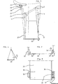
- FIGS 1, 2 and 3 show, in elevation, in plan view and in end view, a first embodiment of stirrup floor 1 adjustable size in length and its attachment to the knife 2 of the saddle 3 by an adjustable stirrup leather 4 hooked at one end on the top of a hoop 5 hinged at 6 on the front sides 7 of the floor 1.
- the hoop 5 is folded back to 8 so that the stirrup is located vertically from the knife 2.
- the pendant 9 the stirrup leather 4 is connected to a double strap 10 attached to two lateral fasteners 11 and 12 at the rear of the floor.
- the floor 1 is made of two sheet metal parts 13 and 14 each having two upwardly bent edges 7a and 7b holding the rider's boot.
- the two parts 13 and 14 are made integral with each other, for example by means of a plate 15 which can be reinforced by lateral folds and having in the longitudinal axis XX 'of the floor, a series of fixing holes 16 adjustable on the parts 13, 14 having corresponding holes, these holes can be replaced by lights making continuous size adjustment.
- the figure 3 shows an example of floor seen end, having a central double fold offset from the foot support surface, allowing the use of head screws for height adjustment without hindering the support of the foot. With this type of floor stirrup, the rider's foot is supported at the front as well as at the back. This first suspension mode of the floor stirrup does not change the pendulum movement of the stirrup relative to the knife 2.
- the figures 4 and 5 show, in top view and in elevation, a second suspension mode of a single-piece floor stirrup 20 made for example in 4 different sizes (in length and in width) and having the same fasteners as on the figure 2 .
- a front stop 22 constituted by an upward fold and an identical abutment 23 at the rear was added for the riders not using spurs.
- the floor is supported at the front by a flat hoop 21 articulated as on the figure 1 .
- the rear suspension of the floor stirrup is performed by engaging the stirrup hook 9 in an existing loop 25 on most stools, which has the effect of widening the base of the suspension of the floor stirrup. by reducing the pendulum effect occurring on the suspension of the figure 1 .
- This pendulum effect can be further reduced by further widening the seat of the suspension at the seat by removing the attachment points 25 and 2.
- the loop 25 is replaced by a U-shaped loop 27 whose ends widened 28 are pierced with a hole in which is engaged a metal rod head 29 passing through the loop of a second stirrup 26, this rod being immobilized by a small cotter pin or any other known means.
- the knife can be replaced by the same type of open loop fixed by a strap 30 sewn on the saddle.
- the figure 6 shows schematically the lateral stall of the outer strap 31 of the floor stirrup during a fall to release the foot of the rider.
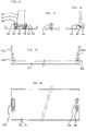
- FIGS. 7 and 8 show, end and top views, a floor stirrup 20 equipped with a spring clip 35 releasing the foot of the rider in case of a fall.
- This fastener version 35 consists of a U-bent spring steel strip each end of which has a hollow recess 36 internally in which are engaged the half-spherical end of a rod 37 on which is passed the corresponding end of the strap 10.
- the fixed fastener 38 is for example constituted by an open loop welded under the stirrup.
- FIGS 9, 10 and 11 show, from the side, from above and from the end, a floor stirrup equipped with a version of spring clip freeing the foot of the rider in the event of a fall.
- This fastener 40 consists of a downwardly bent metal rod 41, one end 42 of which is welded under the stirrup.
- the end of the strap has a hole reinforced by an eyelet engaged on the folded portion 43 of the rod which can be slightly curved.
- a leaf spring 44 attached to a portion of the angle bracket secured to the underside of the stirrup was added. The strap is held laterally in a notch 45 of the back of the stirrup.
- FIGS. 12 and 13 show, in sectional and end views, a version of elastic release means of the foot of a rider mounted on the side of a floor stirrup.
- This means consists of a rod 37 receiving the corresponding end of the strap 10; the rod 37 is engaged in the indentation of a portion of bracket 48 integral with the stirrup and in the footprint of the end of a pusher 49 sliding in a block 50 pushed by a compression spring 51 itself adjustable according to the weight of the rider, by means of a screw 52 acting on the rigidity of the spring.
- the block 50 has an extension 53 which is fixed under the stirrup by means of screws 54.
- the sudden force exerted on the rod 37 causes its ends to come out of the cavities by compressing the spring 51 which release the foot.
- the rigidity of the spring 51 is adjusted by means of a tensile force gauge on the strap according to the weight of the rider.
- a plate 55 fixed under the block 50 makes the elastic release of the only lateral rear strap, which is very important at the end of show jumping to prevent the release of the strap down.
- the figure 14 shows, seen in section, an example of articulation of the arches of Figures 2, 4 and 5 whose bow portion is constituted as that of the classic stirrups.
- the hubs are pierced with a through hole of an axis 56 comprising a head, engaged in a corresponding hole of the folds 7a, 7b of the floor stirrup 20, the pins 56 being immobilized by a clip.
- the figure 15 shows, in section, a means of elastic release of a rear arch holding the back of the foot of a rider equipped with a floor stirrup.
- the arch release means is constituted by two sets of the kind of that of the figure 12 , but whose pusher 57 presses either on an imprint as on the figure 12 , or on a seat formed by a chamfer made on a hole 58 drilled in the two hubs of the hoop 59.
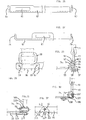
- FIGS 16 to 18 show, seen in section and end, a fastening means or attachment of a detachable stirrup leather, forming a sewn loop, on a floor stirrup 20, consisting of a block 62 having a housing 63 for the passage of a stirrup hook 64 or a strap clinging to a rod 65 engaged with a slight clearance in a hole drilled in the parts 66 and 67 of the block 62, the rod being immobilized after the introduction of the stirrup stirrup by means of a screw 68 squeezing on the rod.
- This clip can be fixed in various places, front and rear, of the stirrup as it will be shown on the Figures 19 to 22 , or on the side of the fold 7a, 7b as on the figure 18 .
- FIGS 19 and 20 show, viewed from the side and from above, a stirrup 75 having a floor with a front attachment 62a and a removable rear attachment 62b supported by the rear stirrups 64a and before 64b fixed on the top of the stirrup by two countersunk screws 69 or other, these two blocks 64 forming a rear stop and front stop to the boot of the rider, boot or other.
- the figure 21 shows in plan view a floor stirrup for riders carrying spurs, having a front tie 62b of stirrup hook 64b as on the figure 20 , while the rear fastener 62a is mounted on the fold 7a or 7b according to the right or left side and an elastic release back fastener, for example 76 ( Fig. 12, 13 ) mounted on the rear fold opposite to that of the fixed strap.
- FIGS 22 and 23 show, viewed from above and from the side, a floor stirrup having multiple holes for securing the various types of removable and elastically release front and back stirrup fasteners and for securing the front fastener to a position which takes into account the evolutionary size of the rider.
- a front fastener 62b it is possible to assemble on the base modular floor stirrup 80 a front fastener 62b according to the size of its foot, either at the end or at one or other of the positions shown by the drilling axes of the fixing holes.
- the rear holes allow to fix either a tie 62a as on the figure 20 , as on the figure 21 , a fastener 77 as on the Figures 24, 25 either an elastic release fastener 76, or for experienced riders a second fastener 77 or 62a.
- FIGS. 24 and 25 show a variant of attachment 77 front, rear or side fixing to a floor stirrup. It is in the form of a folded sheet having an opening with rounded edges 81 for the passage of a stirrup or double strap and two holes on its lower fold 82, fixing on the bottom or the top of the stirrup according to its location.
- FIGS. 26 and 27 show an attachment variant 85 front, rear or side 86 formed directly on a floor stirrup 87 by cutting and rounded edges to receive directly the strap and stirrup.
- FIGS. 28 and 29 show a variant of spring release hook-and-loop fastener in the event of a fall, mounted on the rear side of a floor stirrup. It comprises a ring 90 of strap 91 made prisoner against a small rounded edge 92 retaining the upper part of a plate 93 attached to the rear side 7a, 7b of the stirrup by two screws 99.
- This edge 92 has a rounded against which abuts the ring 90 held in abutment by the preformed end 94 of a leaf spring 95 and a second spring blade 96 of stiffness adjustment, according to its thickness, depending on the weight of the rider.
- the figure 30 shows a variant of a spring release hook-and-loop fastener in the event of a fall, mounted on the rear side of the floor stirrups. It comprises a groove 105 in which is engaged the strap 90 ring 91. This fastener is fixed by two screws 106 on the side 7a, 7b of the stirrup. The lateral retention of the ring 90 in its groove is ensured by a spring blade 107 fixed under the stirrup by two bolts 108.
- the Figures 31 and 32 show an example of inclination limitation stops, during jumping obstacles, floor stirrups having a hoop 109 hinged at the front on a shaft 56 engaged in the side 7a, 7b of the stirrup.
- the hub 110 comprises below, symmetrically to its vertical axis, two stops 111, 112 cooperating with a third stop 113 integral with a plate 114 fixed by screw 115 under the stirrup 20.
Landscapes
- Engineering & Computer Science (AREA)
- Mechanical Engineering (AREA)
- Seats For Vehicles (AREA)
- Footwear And Its Accessory, Manufacturing Method And Apparatuses (AREA)
- Braking Arrangements (AREA)
- Motorcycle And Bicycle Frame (AREA)
Claims (17)
- Sattel (3) an dem ein Steigbügel mit Komplettstützboden für den Fuß eines Reiters montiert ist, der es dem Reiter erlaubt, sich auf seinem Pferd abzustützen, wobei der Steigbügel einen Boden (1, 20) zum Abstützen des vorderen und hinteren Teils des Fußes, einen ersten Steigbügelriemen (4) am vorderen Teil des Steigbügels, einen zweiten Steigbügelriemen (9, 26) hinten an dem Steigbügel aufweist, wobei der Steigbügel dadurch gekennzeichnet ist, dass der erste Steigbügelriemen (4) an einem an den Seiten (7a, 7b) des Bodens (1, 20) gelenkig verbundenen Bügel (5, 21) vorne am Steigbügel befestigt ist, dass der Steigbügel hinten einen doppelten Gurt (10) aufweist, der an zwei seitlichen, mit dem hinteren Teil des Steigbügels zusammenhaltenden Aufhängern (35, 38) befestigt ist, wobei der doppelte Gurt (10) durch den zweiten Steigbügelriemen (9, 26) gehalten ist, und dass der erste und der zweite Steigbügelriemen entweder an einem einzigen Befestigungspunkt (2) oder an jeweilig vorderen (2) und hinteren (25, 27), voneinander beabstandeten Befestigungen an dem Sattel befestigt sind.
- Sattel nach Anspruch 1, dadurch gekennzeichnet, dass der hintere Steigbügelriemen (9) aus dem herabhängenden Teil des ersten Steigbügelriemens (4) besteht, der durch den einzigen Befestigungspunkt, d.h. durch die mit dem Sattel zusammenhaltende Schnalle (2) läuft.
- Sattel nach Anspruch 1 oder 2, dadurch gekennzeichnet, dass der erste Steigbügelriemen (4) und der doppelte Gurt (10) eine Einstellung der Neigung des Bodens aufweisen.
- Sattel nach einem der vorhergehenden Ansprüche, dadurch gekennzeichnet, dass der erste Steigbügelriemen (4) und dessen herabhängender Teil (9) verschiebbar oder fest an der Schnalle (2) befestigt sind.
- Sattel nach einem der vorhergehenden Ansprüche, dadurch gekennzeichnet, dass der hintere Steigbügelriemen (26) lösbar an einer U-förmigen Schnalle (27) befestigt ist, deren erweiterte Enden (28) mit einem Loch durchbohrt sind, in das eine Metallstange mit Kopf (29) geführt wird, die durch die genähte Schlaufe des Steigbügelriemens (26) läuft, wobei diese Stange durch einen Splint oder ein anderes bekanntes Mittel immobilisiert ist, und dass die U-förmige Schlaufe (27) mit dem Sattel durch einen an dem Sattel angenähten Riemen (30) zusammenhält.
- Sattel nach einem der vorhergehenden Ansprüche, dadurch gekennzeichnet, dass der Boden des Steigbügels aus zwei Teilen (13, 14) besteht, die mit einer Gleitschiene zur Einstellung der von der Fußgröße des Reiters abhängigen Länge und mit nach oben gebogenen Seiten (7a, 7b), sowie mit vorderen und hinteren Steigbügelriemenaufhängern ausgestattet ist.
- Sattel nach einem der Ansprüche 1 bis 5, dadurch gekennzeichnet, dass der Boden aus einem Blech (20) besteht, welches zwei nach oben gebogene Seiten (7a, 7b), sowie Löcher zur Befestigung der verschiedenen Aufhänger des Steigbügelriemens und des doppelten Gurtes aufweist.
- Sattel nach Anspruch 6, dadurch gekennzeichnet, dass jeder hintere äußere Aufhänger mit einem elastisch verformbaren Freigabemittel ausgestattet ist, das im Falle eines Sturzes eine Freigabe des doppelten Gurts an der äußeren Seite des Pferdes ermöglicht.
- Sattel nach Anspruch 8, dadurch gekennzeichnet, dass das elastisch verformbare Freigabemittel aus einer U-förmig gebogenen Blattfeder gebildet ist, deren Enden innen eine ausgehöhlte Vertiefung (36) aufweisen, in die halbkugelförmige Enden einer Stange (37) eingesteckt sind, über die das entsprechende Ende des Gurts (10) läuft.
- Sattel nach Anspruch 8, dadurch gekennzeichnet, dass das elastisch verformbare Freigabemittel aus einer das entsprechende Ende des Gurts (10) aufnehmenden Stange (37) besteht, die in die ausgehöhlte Vertiefung eines mit dem Steigbügel zusammenhaltenden Winkelstücks (48) und in die Vertiefung des Endes eines in einem Block (50) gleitenden Stößels (49) eingesteckt ist, der durch eine Druckfeder (51) geschoben wird, die je nach Gewicht des Reiters durch eine auf die Steifigkeit der Feder einwirkende Schraube (52) einstellbar ist, wobei der Block (50) unten an dem Steigbügel (20) mit einer Schraube angeschraubt ist.
- Sattel nach Anspruch 8, dadurch gekennzeichnet, dass das elastisch verformbare Freigabemittel aus einem Federblatt (95) besteht, das auf eine metallische Schlaufe (90) eines Gurts (91) einwirkt, um sie normalerweise gefangen zu halten, und das mit wenigstens einem zusätzlichen Federblatt (96) zusammenwirkt, um die Steifigkeit der Haltung der Schlaufe je nach Gewicht des Reiters einzustellen.
- Sattel nach Anspruch 8, dadurch gekennzeichnet, dass das elastisch verformbare seitliche Freigabemittel ein Gurtaufhänger mit einer Nut (105) ist, in die ein Ring (90) eines Gurts (91) eingesteckt ist, wobei der Gurtaufhänger durch zwei Schrauben (106) an der hinteren Seite (7a, 7b) des Steigbügels befestigt ist, und wobei die seitliche Halterung des Rings (90) in seiner Nut durch ein Federblatt (107) gewährleistet ist, das unter dem Steigbügel mit zwei Bolzen (108) befestigt ist.
- Sattel nach Anspruch 8, dadurch gekennzeichnet, dass das elastisch verformbare seitliche Freigabemittel aus einer nach unten (41) abgebogenen metallischen Stange gebildet ist, von der ein Ende (42) unter dem Steigbügel verschweißt ist, das Ende des Gurts ein durch eine Öse verstärktes Loch aufweist, das auf dem gebogenen Teil (43) der Stange aufgesteckt ist, das leicht gekrümmt sein kann, und durch ein Federblatt (44) gehalten wird, das an einem mit dem unteren Teil des Steigbügels zusammenhaltenden Winkelteilbereich befestigt ist.
- Sattel nach Anspruch 1, dadurch gekennzeichnet, dass ein Zusammenhalt des zweiten Steigbügelriemens (9, 26) mit einem Bügel (59) bewerkstelligt wird, der gelenkig mit einem elastisch verformbaren Freigabemittel mit Stößel (57), Feder (51) und Einstellungsschraube (52) verbunden ist und vorne an dem Steigbügel mit einem anderen gelenkigen Bügel zusammenwirkt.
- Sattel nach Anspruch 1, dadurch gekennzeichnet, dass die Aufhänger (77) des Steigbügelriemens und des Gurts vorne, hinten oder seitlich an dem Steigbügel mit Boden (20) befestigt sind und die Form eines gebogenen Blechs aufweisen, das eine Öffnung mit abgerundeten Rändern (81) für die Durchführung eines Steigbügelriemens oder eines doppelten Gurts und zwei Löcher bei dessen unterem Knick (82), zur Befestigung auf der Unterseite oder oben auf dem Steigbügel gemäß seiner Platzierung auf diesem, aufweist.
- Sattel nach Anspruch 5, dadurch gekennzeichnet, dass er mit zwei gespreizten Schnallenpaaren (2) zur Aufnahme der vorderen (4) und hinteren (26) Steigbügelriemen ausgestattet ist.
- Sattel nach einem der Ansprüche 1, 8 bis 13 und 15, dadurch gekennzeichnet, dass der Steigbügel vorne mit Mitteln zur Beschränkung der Neigung des Bodens beim Springreiten ausgestattet ist, die einen Bügel (109) aufweisen, der vorne mit zwei in die Seite (7a, 7b) des Steigbügels eingesteckten Achsen (56) gelenkig verbunden ist, deren Naben (110), symmetrisch zu ihrer vertikalen Achse, unten zwei Anschläge (111, 112) tragen, die mit einem dritten Anschlag (113) zusammenwirken, der mit einer unter dem Steigbügel (20) mittels einer Schraube (115) verschraubten Platte (114) zusammenhält.
Applications Claiming Priority (1)
| Application Number | Priority Date | Filing Date | Title |
|---|---|---|---|
| PCT/FR2005/000617 WO2006097581A1 (fr) | 2005-03-15 | 2005-03-15 | Etriers a plancher d’appui total pour les pieds des cavaliers |
Publications (2)
| Publication Number | Publication Date |
|---|---|
| EP2016021A1 EP2016021A1 (de) | 2009-01-21 |
| EP2016021B1 true EP2016021B1 (de) | 2012-05-02 |
Family
ID=35385489
Family Applications (1)
| Application Number | Title | Priority Date | Filing Date |
|---|---|---|---|
| EP05739508A Expired - Lifetime EP2016021B1 (de) | 2005-03-15 | 2005-03-15 | Steigbügel mit komplettstützboden für die füsse des reiters |
Country Status (5)
| Country | Link |
|---|---|
| US (1) | US20080047237A1 (de) |
| EP (1) | EP2016021B1 (de) |
| AT (1) | ATE556027T1 (de) |
| CA (1) | CA2594972A1 (de) |
| WO (1) | WO2006097581A1 (de) |
Families Citing this family (6)
| Publication number | Priority date | Publication date | Assignee | Title |
|---|---|---|---|---|
| US20090044499A1 (en) * | 2007-07-02 | 2009-02-19 | Sara Chambers | Riding stirrup |
| FR2934255B1 (fr) * | 2008-07-25 | 2011-03-25 | Gaston Mercier Dev Soc | Dispositif destine a etre suspendu par une courroie a une selle, pour servir d'appui a un pied d'un cavalier, du type etrier d'equitation |
| NO344417B1 (en) * | 2018-01-05 | 2019-12-02 | Maria Terese Engell | Stirrup and combination of stirrup and a leather |
| US11161732B2 (en) | 2019-05-20 | 2021-11-02 | Michel Cabiran | Stirrup and method of using the same |
| US11629045B2 (en) | 2019-05-20 | 2023-04-18 | Michel Cabiran | Stirrup and method of using the same |
| FR3108111B1 (fr) * | 2020-03-16 | 2022-03-04 | Jacques Bardies | Dispositif de réglage de la hauteur des étriers sur les selles d’équitation par poulie et taquet coinceur |
Citations (1)
| Publication number | Priority date | Publication date | Assignee | Title |
|---|---|---|---|---|
| GB191104156A (en) * | 1911-02-18 | 1911-05-11 | Pierre Wenner | Improvements in Stirrups. |
Family Cites Families (10)
| Publication number | Priority date | Publication date | Assignee | Title |
|---|---|---|---|---|
| US469153A (en) * | 1892-02-16 | Saddle-stirrup | ||
| US112652A (en) * | 1871-03-14 | Improvement in stirrups for riding-saddles | ||
| US95857A (en) | 1869-10-12 | Improved stirrup | ||
| US569071A (en) * | 1896-10-06 | Saddle-stirrup | ||
| US872264A (en) * | 1907-01-22 | 1907-11-26 | Jacob Tweit | Stirrup. |
| US949830A (en) * | 1909-04-03 | 1910-02-22 | John Gore Massie | Safety-stirrup. |
| US985346A (en) * | 1910-06-04 | 1911-02-28 | John R Hunter | Safety-stirrup. |
| US1028763A (en) * | 1910-08-05 | 1912-06-04 | John C Miller | Stirrup. |
| FR2616141A1 (fr) | 1987-06-05 | 1988-12-09 | Voland Frederic | Etrier a sustentation longitudinale et auto-equilibree du pied avec selle adaptee |
| US7096652B2 (en) * | 2002-12-06 | 2006-08-29 | Milinda Hendrick Kirkpatrick | Riding pad for two persons |
-
2005
- 2005-03-15 WO PCT/FR2005/000617 patent/WO2006097581A1/fr not_active Ceased
- 2005-03-15 CA CA002594972A patent/CA2594972A1/fr not_active Abandoned
- 2005-03-15 AT AT05739508T patent/ATE556027T1/de active
- 2005-03-15 EP EP05739508A patent/EP2016021B1/de not_active Expired - Lifetime
- 2005-03-15 US US11/814,026 patent/US20080047237A1/en not_active Abandoned
Patent Citations (1)
| Publication number | Priority date | Publication date | Assignee | Title |
|---|---|---|---|---|
| GB191104156A (en) * | 1911-02-18 | 1911-05-11 | Pierre Wenner | Improvements in Stirrups. |
Also Published As
| Publication number | Publication date |
|---|---|
| US20080047237A1 (en) | 2008-02-28 |
| EP2016021A1 (de) | 2009-01-21 |
| WO2006097581A1 (fr) | 2006-09-21 |
| ATE556027T1 (de) | 2012-05-15 |
| CA2594972A1 (fr) | 2006-09-21 |
Similar Documents
| Publication | Publication Date | Title |
|---|---|---|
| EP2016021B1 (de) | Steigbügel mit komplettstützboden für die füsse des reiters | |
| EP2699323B1 (de) | Hilfssystem für ein gleitbrett oder einen schneeschuh | |
| EP1478592A1 (de) | Steigbügel mit automatischer verbindung | |
| JP4920600B2 (ja) | 冬季レクリエーション装置 | |
| EP0940160B1 (de) | Schneesportgerät | |
| EP2272571A1 (de) | Von einem Benutzer angetriebener und einen Mitfahrer aufweisender Rodelschlitten für den Schnee | |
| FR2896761A1 (fr) | Selle de velo comportant deux sieges | |
| FR3027892A1 (fr) | Systeme amovible facilitant le reglage d'un etrier de bete de selle | |
| FR2616141A1 (fr) | Etrier a sustentation longitudinale et auto-equilibree du pied avec selle adaptee | |
| WO2016059335A1 (fr) | Selle d'équitation équipée d'au moins une étrivière ajustable en hauteur | |
| FR2644130A1 (fr) | Dispositif de fixation de securite d'une chaussure sur une pedale de bicyclette | |
| EP3962801B1 (de) | Fussstütze mit verstellbarem lagerpunkt | |
| EP1530987B1 (de) | Snowboardbindung | |
| FR2740350A1 (fr) | Fixation specifique pour un engin de glisse constitue par une planche unique, et engin muni d'une telle fixation | |
| FR2606660A1 (fr) | Raquette a neige | |
| FR2644129A1 (fr) | Dispositif souple de fixation d'une chaussure sur une pedale de bicyclette | |
| CA2127159C (fr) | Bicyclette sur glace | |
| US382690A (en) | Thomas coady | |
| FR3046938A1 (fr) | Dispositif de retenue pour ski polyvalent a fixation debrayable et chaussure de ski adaptee a un tel ski. | |
| FR2789985A1 (fr) | Accessoire de cavalerie, fixe a l'etrier, a fonction pedagogique, de confort et de securite | |
| FR2861602A1 (fr) | Fauteuil ou banc de musculation des para vertebraux et des abdominaux | |
| FR2861065A1 (fr) | L'etrier a plancher | |
| FR2888513A1 (fr) | Dispositif de deplacement sur neige ou glace | |
| FR2657270A1 (fr) | Ensemble de fixation pour une planche de glisse telle qu'un monoski ou un surf de neige. | |
| FR2815878A1 (fr) | Fixation de ski de type avec pivot d'accrochage de la chaussure |
Legal Events
| Date | Code | Title | Description |
|---|---|---|---|
| PUAI | Public reference made under article 153(3) epc to a published international application that has entered the european phase |
Free format text: ORIGINAL CODE: 0009012 |
|
| 17P | Request for examination filed |
Effective date: 20070706 |
|
| AK | Designated contracting states |
Kind code of ref document: A1 Designated state(s): AT BE BG CH CY CZ DE DK EE ES FI FR GB GR HU IE IS IT LI LT LU MC NL PL PT RO SE SI SK TR |
|
| 17Q | First examination report despatched |
Effective date: 20110308 |
|
| GRAP | Despatch of communication of intention to grant a patent |
Free format text: ORIGINAL CODE: EPIDOSNIGR1 |
|
| GRAS | Grant fee paid |
Free format text: ORIGINAL CODE: EPIDOSNIGR3 |
|
| GRAA | (expected) grant |
Free format text: ORIGINAL CODE: 0009210 |
|
| AK | Designated contracting states |
Kind code of ref document: B1 Designated state(s): AT BE BG CH CY CZ DE DK EE ES FI FR GB GR HU IE IS IT LI LT LU MC NL PL PT RO SE SI SK TR |
|
| REG | Reference to a national code |
Ref country code: GB Ref legal event code: FG4D Free format text: NOT ENGLISH |
|
| REG | Reference to a national code |
Ref country code: CH Ref legal event code: EP Ref country code: AT Ref legal event code: REF Ref document number: 556027 Country of ref document: AT Kind code of ref document: T Effective date: 20120515 |
|
| REG | Reference to a national code |
Ref country code: IE Ref legal event code: FG4D Free format text: LANGUAGE OF EP DOCUMENT: FRENCH |
|
| REG | Reference to a national code |
Ref country code: DE Ref legal event code: R096 Ref document number: 602005033992 Country of ref document: DE Effective date: 20120705 |
|
| RAP2 | Party data changed (patent owner data changed or rights of a patent transferred) |
Owner name: POUGNARD, EMMANUELLE Owner name: LANTUEJOUL, LAURENT |
|
| RIN2 | Information on inventor provided after grant (corrected) |
Inventor name: LANTUEJOUL, LAURENT Inventor name: POUGNARD, EMMANUELLE |
|
| REG | Reference to a national code |
Ref country code: NL Ref legal event code: VDEP Effective date: 20120502 |
|
| REG | Reference to a national code |
Ref country code: LT Ref legal event code: MG4D Effective date: 20120502 |
|
| PG25 | Lapsed in a contracting state [announced via postgrant information from national office to epo] |
Ref country code: PL Free format text: LAPSE BECAUSE OF FAILURE TO SUBMIT A TRANSLATION OF THE DESCRIPTION OR TO PAY THE FEE WITHIN THE PRESCRIBED TIME-LIMIT Effective date: 20120502 Ref country code: SE Free format text: LAPSE BECAUSE OF FAILURE TO SUBMIT A TRANSLATION OF THE DESCRIPTION OR TO PAY THE FEE WITHIN THE PRESCRIBED TIME-LIMIT Effective date: 20120502 Ref country code: LT Free format text: LAPSE BECAUSE OF FAILURE TO SUBMIT A TRANSLATION OF THE DESCRIPTION OR TO PAY THE FEE WITHIN THE PRESCRIBED TIME-LIMIT Effective date: 20120502 Ref country code: FI Free format text: LAPSE BECAUSE OF FAILURE TO SUBMIT A TRANSLATION OF THE DESCRIPTION OR TO PAY THE FEE WITHIN THE PRESCRIBED TIME-LIMIT Effective date: 20120502 Ref country code: IS Free format text: LAPSE BECAUSE OF FAILURE TO SUBMIT A TRANSLATION OF THE DESCRIPTION OR TO PAY THE FEE WITHIN THE PRESCRIBED TIME-LIMIT Effective date: 20120902 Ref country code: CY Free format text: LAPSE BECAUSE OF FAILURE TO SUBMIT A TRANSLATION OF THE DESCRIPTION OR TO PAY THE FEE WITHIN THE PRESCRIBED TIME-LIMIT Effective date: 20120502 |
|
| REG | Reference to a national code |
Ref country code: AT Ref legal event code: MK05 Ref document number: 556027 Country of ref document: AT Kind code of ref document: T Effective date: 20120502 |
|
| PG25 | Lapsed in a contracting state [announced via postgrant information from national office to epo] |
Ref country code: PT Free format text: LAPSE BECAUSE OF FAILURE TO SUBMIT A TRANSLATION OF THE DESCRIPTION OR TO PAY THE FEE WITHIN THE PRESCRIBED TIME-LIMIT Effective date: 20120903 Ref country code: SI Free format text: LAPSE BECAUSE OF FAILURE TO SUBMIT A TRANSLATION OF THE DESCRIPTION OR TO PAY THE FEE WITHIN THE PRESCRIBED TIME-LIMIT Effective date: 20120502 Ref country code: GR Free format text: LAPSE BECAUSE OF FAILURE TO SUBMIT A TRANSLATION OF THE DESCRIPTION OR TO PAY THE FEE WITHIN THE PRESCRIBED TIME-LIMIT Effective date: 20120803 |
|
| PG25 | Lapsed in a contracting state [announced via postgrant information from national office to epo] |
Ref country code: SK Free format text: LAPSE BECAUSE OF FAILURE TO SUBMIT A TRANSLATION OF THE DESCRIPTION OR TO PAY THE FEE WITHIN THE PRESCRIBED TIME-LIMIT Effective date: 20120502 Ref country code: AT Free format text: LAPSE BECAUSE OF FAILURE TO SUBMIT A TRANSLATION OF THE DESCRIPTION OR TO PAY THE FEE WITHIN THE PRESCRIBED TIME-LIMIT Effective date: 20120502 Ref country code: RO Free format text: LAPSE BECAUSE OF FAILURE TO SUBMIT A TRANSLATION OF THE DESCRIPTION OR TO PAY THE FEE WITHIN THE PRESCRIBED TIME-LIMIT Effective date: 20120502 Ref country code: DK Free format text: LAPSE BECAUSE OF FAILURE TO SUBMIT A TRANSLATION OF THE DESCRIPTION OR TO PAY THE FEE WITHIN THE PRESCRIBED TIME-LIMIT Effective date: 20120502 Ref country code: EE Free format text: LAPSE BECAUSE OF FAILURE TO SUBMIT A TRANSLATION OF THE DESCRIPTION OR TO PAY THE FEE WITHIN THE PRESCRIBED TIME-LIMIT Effective date: 20120502 Ref country code: CZ Free format text: LAPSE BECAUSE OF FAILURE TO SUBMIT A TRANSLATION OF THE DESCRIPTION OR TO PAY THE FEE WITHIN THE PRESCRIBED TIME-LIMIT Effective date: 20120502 Ref country code: NL Free format text: LAPSE BECAUSE OF FAILURE TO SUBMIT A TRANSLATION OF THE DESCRIPTION OR TO PAY THE FEE WITHIN THE PRESCRIBED TIME-LIMIT Effective date: 20120502 |
|
| PG25 | Lapsed in a contracting state [announced via postgrant information from national office to epo] |
Ref country code: IT Free format text: LAPSE BECAUSE OF FAILURE TO SUBMIT A TRANSLATION OF THE DESCRIPTION OR TO PAY THE FEE WITHIN THE PRESCRIBED TIME-LIMIT Effective date: 20120502 |
|
| PLBE | No opposition filed within time limit |
Free format text: ORIGINAL CODE: 0009261 |
|
| STAA | Information on the status of an ep patent application or granted ep patent |
Free format text: STATUS: NO OPPOSITION FILED WITHIN TIME LIMIT |
|
| 26N | No opposition filed |
Effective date: 20130205 |
|
| PG25 | Lapsed in a contracting state [announced via postgrant information from national office to epo] |
Ref country code: ES Free format text: LAPSE BECAUSE OF FAILURE TO SUBMIT A TRANSLATION OF THE DESCRIPTION OR TO PAY THE FEE WITHIN THE PRESCRIBED TIME-LIMIT Effective date: 20120813 |
|
| REG | Reference to a national code |
Ref country code: DE Ref legal event code: R097 Ref document number: 602005033992 Country of ref document: DE Effective date: 20130205 |
|
| PG25 | Lapsed in a contracting state [announced via postgrant information from national office to epo] |
Ref country code: BG Free format text: LAPSE BECAUSE OF FAILURE TO SUBMIT A TRANSLATION OF THE DESCRIPTION OR TO PAY THE FEE WITHIN THE PRESCRIBED TIME-LIMIT Effective date: 20120802 |
|
| BERE | Be: lapsed |
Owner name: LANTUEJOUL, LAURENT Effective date: 20130331 |
|
| PG25 | Lapsed in a contracting state [announced via postgrant information from national office to epo] |
Ref country code: MC Free format text: LAPSE BECAUSE OF NON-PAYMENT OF DUE FEES Effective date: 20130331 |
|
| REG | Reference to a national code |
Ref country code: CH Ref legal event code: PL |
|
| REG | Reference to a national code |
Ref country code: IE Ref legal event code: MM4A |
|
| PG25 | Lapsed in a contracting state [announced via postgrant information from national office to epo] |
Ref country code: CH Free format text: LAPSE BECAUSE OF NON-PAYMENT OF DUE FEES Effective date: 20130331 Ref country code: BE Free format text: LAPSE BECAUSE OF NON-PAYMENT OF DUE FEES Effective date: 20130331 Ref country code: LI Free format text: LAPSE BECAUSE OF NON-PAYMENT OF DUE FEES Effective date: 20130331 Ref country code: IE Free format text: LAPSE BECAUSE OF NON-PAYMENT OF DUE FEES Effective date: 20130315 |
|
| PG25 | Lapsed in a contracting state [announced via postgrant information from national office to epo] |
Ref country code: TR Free format text: LAPSE BECAUSE OF FAILURE TO SUBMIT A TRANSLATION OF THE DESCRIPTION OR TO PAY THE FEE WITHIN THE PRESCRIBED TIME-LIMIT Effective date: 20120502 |
|
| PG25 | Lapsed in a contracting state [announced via postgrant information from national office to epo] |
Ref country code: HU Free format text: LAPSE BECAUSE OF FAILURE TO SUBMIT A TRANSLATION OF THE DESCRIPTION OR TO PAY THE FEE WITHIN THE PRESCRIBED TIME-LIMIT; INVALID AB INITIO Effective date: 20050315 Ref country code: LU Free format text: LAPSE BECAUSE OF NON-PAYMENT OF DUE FEES Effective date: 20130315 |
|
| REG | Reference to a national code |
Ref country code: FR Ref legal event code: PLFP Year of fee payment: 12 |
|
| PGFP | Annual fee paid to national office [announced via postgrant information from national office to epo] |
Ref country code: FR Payment date: 20160331 Year of fee payment: 12 |
|
| PGFP | Annual fee paid to national office [announced via postgrant information from national office to epo] |
Ref country code: DE Payment date: 20160413 Year of fee payment: 12 Ref country code: GB Payment date: 20160418 Year of fee payment: 12 |
|
| REG | Reference to a national code |
Ref country code: DE Ref legal event code: R119 Ref document number: 602005033992 Country of ref document: DE |
|
| GBPC | Gb: european patent ceased through non-payment of renewal fee |
Effective date: 20170315 |
|
| REG | Reference to a national code |
Ref country code: FR Ref legal event code: ST Effective date: 20171130 |
|
| PG25 | Lapsed in a contracting state [announced via postgrant information from national office to epo] |
Ref country code: DE Free format text: LAPSE BECAUSE OF NON-PAYMENT OF DUE FEES Effective date: 20171003 Ref country code: FR Free format text: LAPSE BECAUSE OF NON-PAYMENT OF DUE FEES Effective date: 20170331 |
|
| PG25 | Lapsed in a contracting state [announced via postgrant information from national office to epo] |
Ref country code: GB Free format text: LAPSE BECAUSE OF NON-PAYMENT OF DUE FEES Effective date: 20170315 |