EP2016269B1 - Device and method for actuating a power control device of an internal combustion engine - Google Patents
Device and method for actuating a power control device of an internal combustion engine Download PDFInfo
- Publication number
- EP2016269B1 EP2016269B1 EP07785891.8A EP07785891A EP2016269B1 EP 2016269 B1 EP2016269 B1 EP 2016269B1 EP 07785891 A EP07785891 A EP 07785891A EP 2016269 B1 EP2016269 B1 EP 2016269B1
- Authority
- EP
- European Patent Office
- Prior art keywords
- input
- power control
- control device
- clutch
- adjusting
- Prior art date
- Legal status (The legal status is an assumption and is not a legal conclusion. Google has not performed a legal analysis and makes no representation as to the accuracy of the status listed.)
- Ceased
Links
- 238000002485 combustion reaction Methods 0.000 title claims description 11
- 238000000034 method Methods 0.000 title description 5
- 230000005540 biological transmission Effects 0.000 claims description 29
- 230000008878 coupling Effects 0.000 description 9
- 238000010168 coupling process Methods 0.000 description 9
- 238000005859 coupling reaction Methods 0.000 description 9
- 230000001419 dependent effect Effects 0.000 description 4
- 230000006872 improvement Effects 0.000 description 1
- 238000002347 injection Methods 0.000 description 1
- 239000007924 injection Substances 0.000 description 1
- 230000009347 mechanical transmission Effects 0.000 description 1
- 238000012986 modification Methods 0.000 description 1
- 230000004048 modification Effects 0.000 description 1
- 230000009467 reduction Effects 0.000 description 1
- 230000004044 response Effects 0.000 description 1
- 239000000243 solution Substances 0.000 description 1
Images

Classifications
-
- F—MECHANICAL ENGINEERING; LIGHTING; HEATING; WEAPONS; BLASTING
- F02—COMBUSTION ENGINES; HOT-GAS OR COMBUSTION-PRODUCT ENGINE PLANTS
- F02D—CONTROLLING COMBUSTION ENGINES
- F02D11/00—Arrangements for, or adaptations to, non-automatic engine control initiation means, e.g. operator initiated
- F02D11/06—Arrangements for, or adaptations to, non-automatic engine control initiation means, e.g. operator initiated characterised by non-mechanical control linkages, e.g. fluid control linkages or by control linkages with power drive or assistance
- F02D11/10—Arrangements for, or adaptations to, non-automatic engine control initiation means, e.g. operator initiated characterised by non-mechanical control linkages, e.g. fluid control linkages or by control linkages with power drive or assistance of the electric type
-
- F—MECHANICAL ENGINEERING; LIGHTING; HEATING; WEAPONS; BLASTING
- F02—COMBUSTION ENGINES; HOT-GAS OR COMBUSTION-PRODUCT ENGINE PLANTS
- F02D—CONTROLLING COMBUSTION ENGINES
- F02D11/00—Arrangements for, or adaptations to, non-automatic engine control initiation means, e.g. operator initiated
- F02D11/06—Arrangements for, or adaptations to, non-automatic engine control initiation means, e.g. operator initiated characterised by non-mechanical control linkages, e.g. fluid control linkages or by control linkages with power drive or assistance
- F02D11/10—Arrangements for, or adaptations to, non-automatic engine control initiation means, e.g. operator initiated characterised by non-mechanical control linkages, e.g. fluid control linkages or by control linkages with power drive or assistance of the electric type
- F02D2011/101—Arrangements for, or adaptations to, non-automatic engine control initiation means, e.g. operator initiated characterised by non-mechanical control linkages, e.g. fluid control linkages or by control linkages with power drive or assistance of the electric type characterised by the means for actuating the throttles
- F02D2011/103—Arrangements for, or adaptations to, non-automatic engine control initiation means, e.g. operator initiated characterised by non-mechanical control linkages, e.g. fluid control linkages or by control linkages with power drive or assistance of the electric type characterised by the means for actuating the throttles at least one throttle being alternatively mechanically linked to the pedal or moved by an electric actuator
-
- F—MECHANICAL ENGINEERING; LIGHTING; HEATING; WEAPONS; BLASTING
- F02—COMBUSTION ENGINES; HOT-GAS OR COMBUSTION-PRODUCT ENGINE PLANTS
- F02D—CONTROLLING COMBUSTION ENGINES
- F02D2200/00—Input parameters for engine control
- F02D2200/02—Input parameters for engine control the parameters being related to the engine
- F02D2200/04—Engine intake system parameters
- F02D2200/0404—Throttle position
-
- F—MECHANICAL ENGINEERING; LIGHTING; HEATING; WEAPONS; BLASTING
- F02—COMBUSTION ENGINES; HOT-GAS OR COMBUSTION-PRODUCT ENGINE PLANTS
- F02D—CONTROLLING COMBUSTION ENGINES
- F02D2200/00—Input parameters for engine control
- F02D2200/60—Input parameters for engine control said parameters being related to the driver demands or status
- F02D2200/602—Pedal position
Definitions
- the invention relates to a device for actuating a power control device of an internal combustion engine comprising a driver-actuated input device for driver input of a power desired, a sensor device for detecting the position of the input device and generating a corresponding output signal and an adjusting device for adjusting the power control device taking into account the output signal of the sensor device, wherein the Power control device by means of the adjusting device by the signal of the input device can be actuated deviating and a method for actuating such a power control device.
- the DE 198 25 283 A1 describes a motor power control for motor vehicles with a power control element, which is decoupled from the power demand of the driver reproducing operation of the accelerator pedal in response to various operating parameters controllable by means of an electronic control unit.
- this engine power control is in the event of a fault, especially in case of failure of the connection between a sensor associated with the accelerator pedal and the control unit, limited in an emergency operation, the maximum engine power and still ensures a very good driving dynamics.
- the safety in the event of a fault is already substantially increased in the known engine output control, however, a further improvement in safety is possible.
- a throttle control apparatus in which a reduction gear having a semicircular ratchet wheel is provided coaxially with a motor shaft between an engine and a throttle valve.
- a device which comprises not only mechanical transmission means but also electromechanical transmission means with a switchable coupling element between the accelerator pedal and the throttle valve, wherein the coupling element is a double-acting coupling element.
- the accelerator pedal can be connected to the throttle valve via the mechanical or electromechanical transmission means.
- a device for controlling the application of vehicle engines, in which in addition to the foot-operated accelerator lever, an adjusting device is provided which is coupled to the control member for the application of the motor, such as a throttle or a control rod of an injection pump.
- the EP 0 427 410 shows a throttle valve actuator for connecting a throttle valve of a motor vehicle with the accelerator pedal either in a direct drive mode or in a controlled drive mode.
- the object of the invention is therefore to increase safety in an aforementioned device for actuating a power control device of an internal combustion engine and in particular to prevent inadvertently high engine power due to a driver not wanted by the driver control of the power control element.
- the invention is based on the idea that the adjusting device is connected to the power control device by means of a coupling having an input part and an output part, whose input part is assigned to the adjusting device and whose output part is assigned to the power control device. This makes it possible to decouple the actuating device from the power control device, so that the position of the actuating device is no longer relevant to the position of the power control device.
- a mechanical connection between the input device and power control device is effective.
- the desired power input by means of the input device on the driver side is preferred to the position of the actuating device based on sensor signals, thus increasing safety.
- the input part of the clutch can be decoupled from its output part.
- the position of the adjusting device for the power control device is ineffective.
- the clutch is a releasable, pawl clutch.
- the pawl clutch is an overrunning clutch - and overhohlkupplung - and includes an input and an output part, which direction of rotation dependent pawls are connected to each other.
- input and clutch output are connected in the reverse direction with each other, but the connection is releasable by means of an unlocking, so that a relative rotation between the input and an output part can also be enabled in the reverse direction.
- a contoured first transmission element assigned to the input device corresponds to a second transmission element having a counter contour and connected to a pawl.
- the first transmission element on a flat extension, which with a pin-shaped extension of the pawl corresponds.
- an operation of the power control device by means of the adjusting device in consideration of the output signal of the sensor device for detecting the position of the input device is possible in a normal operation, while in a deviation of the input by means of the input side driver input reduced power requirement of the set by means of the actuator position of the power control device at least a predetermined amount in the closing direction of the power control device, a positive connection between the first and second transmission element comes about and can be done deviating from the actuator actuation.
- the pawl can be brought into the unlocked position.
- the pawl by means of the first transmission element is releasable.
- the pawl is movably mounted in a part of the clutch and corresponds actuation direction dependent force-transmitting with the other part of the clutch.
- the pawl in the output part of the clutch is longitudinally displaceable, biased in the reverse direction by a spring, mounted and corresponds by means of an actuating direction-dependent effective toothing with a toothing of the input part of the clutch.
- the pawl is mounted in the input part of the clutch and corresponds with a toothing of the output part of the clutch
- the invention is further based on the idea that in a method for actuating a power control device of an internal combustion engine in the case of a deviation of the desired power input by means of the input device from the position of the power control device set by the adjusting device by at least a predetermined amount in the closing direction, the desired power for adjusting the power control device is inputted to the driver via the input device.
- the control device in the case of a preference for the power requirement entered by the driver on the input side, the control device is decoupled from the power control device and the power control device is actuated directly by means of the input device.
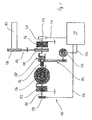
- FIG. 1 1 shows a device 100 for actuating a power control device 134 of an internal combustion engine (not shown here) with a clutch 138 arranged between an actuating device 122 and the power control device 134.
- the device 100 is for operating an internal combustion engine of a motorcycle and the power control device 134 is a throttle valve, however, in one embodiment, an internal combustion engine of a motor vehicle can be actuated and / or the power control device 134 is a Kraftstoffzumessventil or means for Hub Whynver selectedung an intake valve of an internal combustion engine be.
- the throttle valve is pivotable in the opening direction and to reduce the power in the closing direction.
- the throttle valve is rotatably connected to a throttle valve shaft 130, which is rotatable either by means of an here designed as an electric motor actuator 122 or manually by means of a here designed as a throttle grip input device 102.
- the driver inputs a power by means of the input device 102 by correspondingly rotating the throttle grip.
- a first pulley 104 is rotatably connected, which operates via a cable 106, a second pulley 108.
- the second pulley 108 is rotatably connected to a shaft 110, so that upon actuation of the throttle grip the shaft 110 is rotated.
- the rotation or the rotational position of the shaft 110 can be detected by means of a sensor 112, which is connected in a signal-conducting manner to a control device 118 by a line 114.
- the rotation or the rotational position of the throttle valve shaft 130 can be detected, which is connected to the control device 118 in a signal-conducting manner with a line 126.
- the control device 118 Based on the signals of the sensors 112, 128 and optionally further signals and / or stored information, the control device 118 outputs via a line 120 a driver's desired performance control signal to the actuator 122, which - in this case by means of a gear 124 with an input part of Clutch 138 is connected - with the throttle shaft 130 is in rotary drive connection.
- Both the shaft 110 and the throttle shaft 130 are acted upon by springs 116, 132 which are supported on the housing side in the throttle valve closing direction.
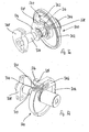
- FIG. 2 shows a detailed view of the clutch 138, which is designed as a releasable pawl clutch 200 in this embodiment.
- the pawl clutch 200 allows actuation of the power control device 134 either manually by means of the input device 102 or by means of the adjusting device 122.
- FIGS. 3a and 3b Detail views of the input part 302 and the unlocking of the unlockable locking clutch 300 and the output part 304 are in the FIGS. 3a and 3b shown.
- the pawl clutch 200, 333 comprises a pot-shaped input part 202, 302, which has a toothing 348 for connection to the toothing 344 of a pawl 206, 342 radially on the inside.
- a likewise cup-shaped output part 204, 304 is arranged, wherein the edge of the input part 202, 302 surrounds the edge of the output part 204, 304 and enclose input and output part of a disk-shaped space.
- the pawl 206, 342 is arranged, in this case, the output part 204, 304 a guide 346, in which the pawl 206, 342 is guided longitudinally displaceable.
- the guide 346 and the edge of the output part 204, 304 have an opening 220, 320 through which the pawl 206, 342 with its toothing 344 with the teeth 348 of the input part 202, 302 can correspond.
- the pawl 206, 342 is biased by a spring 340.
- the output part 204, 304 has a slot-shaped cutout 222, through which a pin-shaped extension 218, 318 of the pawl 206, 342 protrudes.
- the extension 218, 318 is designed with a spherical end.
- the extension 218, 318 corresponds to a flat extension 216, 316 of a disk-shaped transmission element 214, 314.
- the present arrangement forms a safety device, which in a deviation of the input by means of the input device 102 (throttle grip) driver input side reduced power desired from the set by means of the adjusting device 122 (electric motor) position of the power control device 134 (throttle) by at least a predetermined amount, a preferred consideration of means the input device 102 (throttle grip) ensures driver input side reduced power desired.
- the second pulley 108, 208 forms a first transmission element 214, 314, which has a flat extension 216, 316 and is arranged in the axial direction adjacent to the clutch 138, 200, 300, wherein the first transmission element 214, 314 and the clutch 138, 200 , 300 are each rotatable about at least approximately aligned axes relative to each other.
- the flat projection 216, 316 corresponds to the pin-shaped extension 218, 318 of the pawl 206, 342.
- the planar extension 216, 316 arrives at the pin-shaped extension 218, 318 to the plant or exerts a predetermined value exceeding pressure on this, wherein the first transmission element 214, 314 form-fit force-transmitting connected to the locking pawl 206, 342 second transmission element 220 and the pawl 206, 342 against the force of the spring 340 in Unlocking is moved.
- the teeth 344 of the pawl 206, 342 of the teeth 348 of the input part 202, 302 of the clutch 138, 200, 300 and the connection between input part 202, 302 and output part 204, 304 of the clutch 138, 200, 300 is released.
- the actuator 122 (electric motor) from the power control device 134 (throttle) is decoupled and the input device 102 (throttle grip) via the transmission elements 214, 314, 218, 318, 220, the pawl 206, 342 and the spring 340 with the Output part 204, 304 of the clutch 138, 200, 300 and thus with the power control device 134 (throttle) coupled.
- the power control device 134 is actuated in accordance with the setting device 122.
- the coupling input part 202, 302, the coupling output part 204, 304 with the second transmission element 342 and the first transmission element 214, 314 are arranged on a common shaft 310, wherein the pawl clutch 200, 300 with coupling input part 202, 302 and coupling output part 204, 304 with second transmission element 342 are rotatably mounted on the shaft 310 and the first transmission element 214, 314 with the shaft 310 is rotatably connected.
- the shaft 310 is kinematically coupled to the input device 102 (throttle grip), so that upon actuation of the input device 102, the shaft 310 and thus also the first transmission element 214, 314 are rotated.
- the adjusting device (electric motor) 122 which is coupled to the coupling input part 202, 302
- the clutch 200, 300 and thus also the second transmission element 342 is tracked according to the input by means of the input device 102 (throttle grip) driver input power requirement and only one small difference between the position of the input device 102 and the actuator 122 occurs, the flat projection 216, 316 of the first transmission element 214, 314 does not act on the pin-shaped extension 218, 318 of the second transmission element 342.
Landscapes
- Engineering & Computer Science (AREA)
- Chemical & Material Sciences (AREA)
- Combustion & Propulsion (AREA)
- Mechanical Engineering (AREA)
- General Engineering & Computer Science (AREA)
- Control Of Throttle Valves Provided In The Intake System Or In The Exhaust System (AREA)
Description
Die Erfindung betrifft eine Einrichtung zur Betätigung einer Leistungssteuerungseinrichtung einer Brennkraftmaschine umfassend eine fahrerbetätigbare Eingabeeinrichtung zur fahrerseitigen Eingabe eines Leistungswunsches, eine Sensoreinrichtung zur Erfassung der Stellung der Eingabeeinrichtung und Generierung eines entsprechenden Ausgangssignals und eine Stelleinrichtung zur Verstellung der Leistungssteuerungseinrichtung unter Berücksichtung des Ausgangssignals der Sensoreinrichtung, wobei die Leistungssteuerungseinrichtung mittels der Stelleinrichtung vom Signal der Eingabeeinrichtung abweichend betätigbar ist sowie ein Verfahren zur Betätigung einer derartigen Leistungssteuerungseinrichtung.The invention relates to a device for actuating a power control device of an internal combustion engine comprising a driver-actuated input device for driver input of a power desired, a sensor device for detecting the position of the input device and generating a corresponding output signal and an adjusting device for adjusting the power control device taking into account the output signal of the sensor device, wherein the Power control device by means of the adjusting device by the signal of the input device can be actuated deviating and a method for actuating such a power control device.
Die
Aus der
Aus der
Aus der
Aus der
Die
Aufgabe der Erfindung ist es daher, bei einer eingangs genannten Einrichtung zur Betätigung einer Leistungssteuerungseinrichtung einer Brennkraftmaschine die Sicherheit zu erhöhen und insbesondere eine unbeabsichtigt hohe Motorleistung aufgrund einer vom Fahrer nicht gewollten Ansteuerung des Leistungssteuerorgans zu verhindern.The object of the invention is therefore to increase safety in an aforementioned device for actuating a power control device of an internal combustion engine and in particular to prevent inadvertently high engine power due to a driver not wanted by the driver control of the power control element.
Die Lösung dieser Aufgabe erfolgt mit einer Einrichtung mit den Merkmalen des Anspruchs 1 sowie einem Verfahren mit den Merkmalen des Anspruchs 10. Vorteilhafte Ausgestaltungen und Weiterbildungen der Erfindung sind Gegenstand der Unteransprüche.The solution of this object is achieved with a device having the features of claim 1 and a method having the features of claim 10. Advantageous embodiments and modifications of the invention are the subject of the dependent claims.
Der Erfindung liegt die Idee zugrunde, dass die Stelleinrichtung mit der Leistungssteuerungseinrichtung mittels einer ein Eingangs- und ein Ausgangsteil aufweisenden Kupplung verbunden ist, deren Eingangsteil der Stelleinrichtung und deren Ausgangsteil der Leistungssteuerungseinrichtung zugeordnet ist. Damit ist es möglich, die Stelleinrichtung von der Leistungssteuerungseinrichtung zu entkoppeln, so dass die Stellung der Stelleinrichtung nicht mehr für die Stellung der Leistungssteuerungseinrichtung maßgeblich ist.The invention is based on the idea that the adjusting device is connected to the power control device by means of a coupling having an input part and an output part, whose input part is assigned to the adjusting device and whose output part is assigned to the power control device. This makes it possible to decouple the actuating device from the power control device, so that the position of the actuating device is no longer relevant to the position of the power control device.
Vorzugsweise ist bei einem Abweichen des mittels der Eingabeeinrichtung fahrerseitig eingegebenen reduzierten Leistungswunsches von der mittels der Stelleinrichtung eingestellten Stellung der Leistungssteuerungseinrichtung um mindestens einen vorgegebenen Betrag in Schließrichtung der Leistungssteuerungseinrichtung eine mechanische Verbindung zwischen Eingabeeinrichtung und Leistungssteuerungseinrichtung wirksam. Dadurch wird der mittels der Eingabeeinrichtung mechanisch fahrerseitig eingegebene Leistungswunsch der auf Sensorsignalen basierenden Stellung der Stelleinrichtung vorgezogen und so die Sicherheit erhöht.Preferably, in the case of a deviation of the reduced power requirement entered by the driver on the input side from the position of the power control device adjusted by means of the actuating device by at least a predetermined amount in the closing direction the power control device, a mechanical connection between the input device and power control device is effective. As a result, the desired power input by means of the input device on the driver side is preferred to the position of the actuating device based on sensor signals, thus increasing safety.
Außerdem ist es bevorzugt, wenn bei einem Abweichen des mittels der Eingabeeinrichtung fahrerseitig eingegebenen reduzierten Leistungswunsches von der mittels der Stelleinrichtung eingestellten Stellung der Leistungssteuerungseinrichtung um mindestens einen vorgegebenen Betrag in Schließrichtung der Leistungssteuerungseinrichtung das Eingangsteil der Kupplung von deren Ausgangsteil entkoppelbar ist. Dadurch wird die Stellung der Stelleinrichtung für die Leistungssteuerungseinrichtung unwirksam.In addition, it is preferred if, in the case of a deviation of the reduced power requirement entered by the input device from the setting of the power control device by at least a predetermined amount in the closing direction of the power control device, the input part of the clutch can be decoupled from its output part. As a result, the position of the adjusting device for the power control device is ineffective.
Besonders vorteilhaft ist es, wenn die Kupplung eine entsperrbare, Sperrklinkenkupplung ist. Die Sperrklinkenkupplung ist eine Freilaufkupplung - auch Überhohlkupplung - und umfasst ein Eingangs- und ein Ausgangsteil, welche drehrichtungsabhängig mittel Sperrklinken miteinander verbindbar sind. Bei der bevorzugten entsperrbaren Sperrktinkenkupptung sind Kupplungseingang und Kupplungsausgang in Sperrrichtung miteinander verbunden, die Verbindung ist jedoch mittels einer Entsperreinrichtung lösbar, so dass eine Relativdrehung zwischen Eingangs- und ein Ausgangsteil auch in Sperrrichtung ermöglicht werden kann.It is particularly advantageous if the clutch is a releasable, pawl clutch. The pawl clutch is an overrunning clutch - and overhohlkupplung - and includes an input and an output part, which direction of rotation dependent pawls are connected to each other. In the preferred unlockable Sperrktinkenkupptung clutch input and clutch output are connected in the reverse direction with each other, but the connection is releasable by means of an unlocking, so that a relative rotation between the input and an output part can also be enabled in the reverse direction.
Zur Verbindung der Eingabeeinrichtung mit der Leistungssteuerungseinrichtung ist es von Vorteil, wenn ein der Eingabeeinrichtung zugeordnetes konturiertes erstes Übertragungselement mit einem zweiten, eine Gegenkontur aufweisenden Übertragungselement, das mit einer Sperrklinke verbunden ist, korrespondiert. Vorzugsweise weist das erste Übertragungselement einen flächigen Fortsatz auf, welcher mit einem stiftförmigen Fortsatz der Sperrklinke korrespondiert. Mit dieser Ausführung ist in einem Normalbetrieb eine Betätigung der Leistungssteuerungseinrichtung mittels der Stelleinrichtung unter Berücksichtung des Ausgangssignals der Sensoreinrichtung zur Erfassung der Stellung der Eingabeeinrichtung möglich, während bei einem Abweichen des mittels der Eingabeeinrichtung fahrerseitig eingegebenen reduzierten Leistungswunsches von der mittels der Stelleinrichtung eingestellten Stellung der Leistungssteuerungseinrichtung um mindestens einen vorgegebenen Betrag in Schließrichtung der Leistungssteuerungseinrichtung ein Formschluss zwischen erstem und zweiten Übertragungselement zustande kommt und eine von der Stelleinrichtung abweichende Betätigung erfolgen kann.To connect the input device to the power control device, it is advantageous if a contoured first transmission element assigned to the input device corresponds to a second transmission element having a counter contour and connected to a pawl. Preferably, the first transmission element on a flat extension, which with a pin-shaped extension of the pawl corresponds. With this embodiment, an operation of the power control device by means of the adjusting device in consideration of the output signal of the sensor device for detecting the position of the input device is possible in a normal operation, while in a deviation of the input by means of the input side driver input reduced power requirement of the set by means of the actuator position of the power control device at least a predetermined amount in the closing direction of the power control device, a positive connection between the first and second transmission element comes about and can be done deviating from the actuator actuation.
Bevorzugt ist es, wenn bei einer wirksamen mechanischen Verbindung zwischen Eingabeeinrichtung und Leistungssteuerungseinrichtung die Sperrklinke in Entsperrposition bringbar ist. Dazu ist die Sperrklinke mittels des ersten Übertragungselements lösbar.It is preferred if, in the case of an effective mechanical connection between the input device and the power control device, the pawl can be brought into the unlocked position. For this purpose, the pawl by means of the first transmission element is releasable.
Gemäß einer sehr vorteilhaften Ausgestaltung der Erfindung ist die Sperrklinke in einem Teil der Kupplung bewegbar gelagert ist und korrespondiert betätigungsrichtungsabhängig kraftübertragend mit dem anderen Teil der Kupplung. Zweckmäßigerweise ist die Sperrklinke im Ausgangsteil der Kupplung längsverschiebbar, in Sperrrichtung mittels einer Feder vorgespannt, gelagert und korrespondiert mittels einer betätigungsrichtungsabhängig wirksamen Verzahnung mit einer Verzahnung des Eingangsteils der Kupplung. Jedoch kann es auch günstig sein, wenn die Sperrklinke im Eingangsteil der Kupplung gelagert ist und mit einer Verzahnung des Ausgangsteils der Kupplung korrespondiertAccording to a very advantageous embodiment of the invention, the pawl is movably mounted in a part of the clutch and corresponds actuation direction dependent force-transmitting with the other part of the clutch. Conveniently, the pawl in the output part of the clutch is longitudinally displaceable, biased in the reverse direction by a spring, mounted and corresponds by means of an actuating direction-dependent effective toothing with a toothing of the input part of the clutch. However, it may also be advantageous if the pawl is mounted in the input part of the clutch and corresponds with a toothing of the output part of the clutch
Der Erfindung liegt ferner die Idee zugrunde, dass bei einem Verfahren zur Betätigung einer Leistungssteuerungseinrichtung einer Brennkraftmaschine bei einem Abweichen des mittels der Eingabeeinrichtung fahrerseitig eingegebenen Leistungswunsches von dem mittels der Stelleinrichtung eingestellten Position der Leistungssteuerungseinrichtung um mindestens einen vorgegebenen Betrag in Schließrichtung der mittels der Eingabeeinrichtung fahrerseitig eingegebenen Leistungswunsch zur Verstellung der Leistungssteuerungseinrichtung vorrangig herangezogen wird.The invention is further based on the idea that in a method for actuating a power control device of an internal combustion engine in the case of a deviation of the desired power input by means of the input device from the position of the power control device set by the adjusting device by at least a predetermined amount in the closing direction, the desired power for adjusting the power control device is inputted to the driver via the input device.
Gemäß einer besonders bevorzugten Weiterbildung des erfindungsgemäßen Verfahrens wird im Falle einer Bevorzugung des mittels der Eingabeeinrichtung fahrerseitig eingegebenen Leistungswunsches die Stelleinrichtung von der Leistungssteuerungseinrichtung entkoppelt und die Leistungssteuerungseinrichtung mittels der Eingabeeinrichtung unmittelbar betätigt.According to a particularly preferred development of the method according to the invention, in the case of a preference for the power requirement entered by the driver on the input side, the control device is decoupled from the power control device and the power control device is actuated directly by means of the input device.
Weitere Vorteile ergeben sich, wenn außerdem bei einer fahrerseitigen Eingabe eines erhöhten Leistungswunsches mittels der Eingabeeinrichtung mit einem einen vorgegebenen Gradienten übersteigenden Gradienten eine Betätigung der Leistungssteuerungseinrichtung mittels der Stelleinrichtung vom Signal der Eingabeeinrichtung abweichend mit einem begrenzten Gradienten erfolgt. Damit wird eine übermäßig schnelle Betätigung der Leistungssteuerungseinrichtung in Öffnungsrichtung verhindert.Further advantages are obtained if, in addition, in the case of a driver-side input of an increased power requirement by means of the input device with a gradient exceeding a predetermined gradient, an actuation of the power control device by means of the control device takes place differently from the signal of the input device with a limited gradient. Thus, an excessively fast actuation of the power control device in the opening direction is prevented.
Nachfolgend ist ein besonders zu bevorzugendes Ausführungsbeispiel der Erfindung unter Bezugnahme auf Figuren näher erläutert, dabei zeigen schematisch und beispielhaft
- Figur 1
- eine Einrichtung zur Betätigung einer Leistungssteuerungseinrichtung einer Brennkraftmaschine mit einer zwischen einer Stelleinrichtung und der Leistungssteuerungseinrichtung angeordneten Kupplung,
- Figur 2
- eine Detailansicht einer entsperrbaren Sperrklinkenkupplung,
- Figur 3a
- eine Detailansicht eines Eingangsteils sowie einer Entsperreinrichtung einer entsperrbaren Sperrklinkenkupplung und
- Figur 3b
- eine Detailansicht eines Ausgangsteils einer entsperrbaren Sperrklinkenkupplung.
- FIG. 1
- a device for actuating a power control device of an internal combustion engine with a clutch arranged between an actuating device and the power control device,
- FIG. 2
- a detailed view of a releasable pawl clutch,
- FIG. 3a
- a detailed view of an input part and an unlocking a releasable pawl clutch and
- FIG. 3b
- a detailed view of an output part of a releasable pawl clutch.
Im vorliegenden Ausführungsbeispiel dient die Einrichtung 100 zur Betätigung einer Brennkraftmaschine eines Kraftrads und die Leistungssteuerungseinrichtung 134 ist eine Drosselklappe, jedoch kann in einem Ausführungsbeispiel auch eine Brennkraftmaschine eines Kraftfahrzeugs betätigt werden und/oder die Leistungssteuerungseinrichtung 134 ein Kraftstoffzumessventil oder eine Einrichtung zur Hubhöhenveränderung eines Einlassventils einer Brennkraftmaschine sein.In the present embodiment, the
Zur Steigerung der Brennkraftmaschinenleistung ist die Drosselklappe in Öffnungsrichtung und zur Reduzierung der Leistung in Schließrichtung verschwenkbar. Hierzu ist die Drosselklappe drehfest mit einer Drosselklappenwelle 130 verbunden, die entweder mittels einer hier als Elektromotor ausgebildeten Stelleinrichtung 122 oder manuell mittels einer hier als Gasdrehgriff ausgebildeten Eingabeeinrichtung 102 verdrehbar ist.To increase the engine power, the throttle valve is pivotable in the opening direction and to reduce the power in the closing direction. For this purpose, the throttle valve is rotatably connected to a
In einem normalen Fahrbetrieb gibt der Fahrer mittels der Eingabeeinrichtung 102 einen Leistungswunsch ein, indem er den Gasdrehgriff entsprechend verdreht. Mit dem Gasdrehgriff ist drehfest eine erste Seilscheibe 104 verbunden, die über einen Seilzug 106 eine zweite Seilscheibe 108 betätigt. Die zweite Seilscheibe 108 ist mit einer Welle 110 drehfest verbunden, so dass bei einer Betätigung des Gasdrehgriffs die Welle 110 verdreht wird. Die Verdrehung oder die Drehstellung der Welle 110 ist mittels eines Sensors 112 detektierbar, der mit einer Leitung 114 signalleitend mit einer Steuereinrichtung 118 verbunden ist. Mittels eines weiteren Sensors 128 ist die Verdrehung oder die Drehstellung der Drosselklappenwelle 130 detektierbar, der mit einer Leitung 126 signalleitend mit der Steuereinrichtung 118 verbunden ist. Basierend auf den Signalen der Sensoren 112, 128 und gegebenenfalls weiterer Signale und/oder gespeicherter Informationen gibt die Steuereinrichtung 118 über eine Leitung 120 ein dem Leistungswunsch des Fahrers entsprechendes Steuersignal an die Stelleinrichtung 122 aus, die - vorliegend mittels eines Getriebes 124 mit einem Eingangsteil der Kupplung 138 verbunden - mit der Drosselklappenwelle 130 in Drehantriebsverbindung steht. Sowohl die Welle 110 als auch die Drosselklappenwelle 130 sind mittels sich gehäuseseitig abstützenden Federn 116, 132 in Drosselklappenschließrichtung beaufschlagt.In a normal driving operation, the driver inputs a power by means of the
Detailansichten des Eingangsteils 302 sowie der Entsperreinrichtung der entsperrbaren Sperrklikenkupplung 300 sowie deren Ausgangsteil 304 sind in den
Die Sperrklinkenkupplung 200, 333 umfasst ein topfförmiges Eingangsteil 202, 302, das radial innenseitig eine Verzahnung 348 zur Verbindung mit der Verzahnung 344 einer Sperrklinke 206, 342 aufweist. In dem Eingangsteil 202, 302 ist ein ebenfalls topfförmiges Ausgangsteil 204, 304 angeordnet, wobei der Rand des Eingangsteils 202, 302 den Rand des Ausgangsteils 204, 304 umgreift und Eingangs- und Ausgangsteil eine scheibenförmigen Raum umschließen. In diesem Raum ist die Sperrklinke 206, 342 angeordnet, vorliegend weist das Ausgangsteil 204, 304 eine Führung 346 auf, in der die Sperrklinke 206, 342 längsverschiebbar geführt ist. Die Führung 346 und der Rand des Ausgangsteils 204, 304 weisen eine Öffnung 220, 320 auf, durch die die Sperrklinke 206, 342 mit ihrer Verzahnung 344 mit der Verzahnung 348 des Eingangsteils 202, 302 korrespondieren kann. In Sperrrichtung ist die Sperrklinke 206, 342 mittels einer Feder 340 vorgespannt. In axialer Richtung weist das Ausgangsteil 204, 304 einen langlochförmigen Ausschnitt 222 auf, durch den ein stiftförmiger Fortsatz 218, 318 der Sperrklinke 206, 342 hindurch ragt. Vorliegend ist der Fortsatz 218, 318 mit einem kugelförmigen Ende ausgestaltet. Zur Betätigung der Sperrklinke 206, 342 korrespondiert der Fortsatz 218, 318 mit einem flächigen Fortsatz 216, 316 eines scheibenförmigen Übertragungselements 214, 314.The
Die Vorliegende Anordnung bildet eine Sicherheitseinrichtung, welche bei einem Abweichen des mittels der Eingabeeinrichtung 102 (Gasdrehgriff) fahrerseitig eingegebenen reduzierten Leistungswunsches von der mittels der Stelleinrichtung 122 (Elektromotor) eingestellten Stellung der Leistungssteuerungseinrichtung 134 (Drosselklappe) um mindestens einen vorgegebenen Betrag eine bevorzugte Berücksichtigung des mittels der Eingabeeinrichtung 102 (Gasdrehgriff) fahrerseitig eingegebenen reduzierten Leistungswunsches gewährleistet.The present arrangement forms a safety device, which in a deviation of the input by means of the input device 102 (throttle grip) driver input side reduced power desired from the set by means of the adjusting device 122 (electric motor) position of the power control device 134 (throttle) by at least a predetermined amount, a preferred consideration of means the input device 102 (throttle grip) ensures driver input side reduced power desired.
Die zweite Seilscheibe 108, 208 bildet ein erstes Übertragungselement 214, 314, das einen flächigen Fortsatz 216, 316 aufweist und ist in axialer Richtung benachbart der Kupplung 138, 200, 300 angeordnet, wobei das erste Übertragungselement 214, 314 und die Kupplung 138, 200, 300 jeweils um zumindest annähernd fluchtende Achsen relativ zueinander drehbar sind. Der flächige Fortsatz 216, 316 korrespondiert mit dem stiftförmigen Fortsatz 218, 318 der Sperrklinke 206, 342. Indem bei einem normalen Fahrbetrieb der Fortsatz 216, 316 am Fortsatz 218, 318 nicht oder nur mit einem geringen Druck anliegt, kann eine Betätigung der Leistungssteuerungseinrichtung 134 mittels der Stelleinrichtung 122 erfolgen. Hierzu ist ein die Stelleinrichtung 122 mit dem Eingangsteil 202, 302 der Kupplung 138, 200, 300 verbunden.The
Bei einem Abweichen des mittels der Eingabeeinrichtung 102 (Gasdrehgriff) fahrerseitig eingegebenen reduzierten Leistungswunsches von der mittels der Stelleinrichtung 122 (Elektromotor) eingestellten Stellung der Leistungssteuerungseinrichtung 134 (Drosselklappe) um mindestens einen vorgegebenen Betrag kommt der flächige Fortsatz 216, 316 an dem stiftförmigen Fortsatz 218, 318 zur Anlage bzw. übt einen einen vorgegebenen Wert übersteigenden Druck auf diesen aus, wobei das erste Übertragungselement 214, 314 formschlüssig kraftübertragend mit dem als Sperrklinke 206, 342 ausgebildeten zweiten Übertragungselement 220 verbunden und die Sperrklinke 206, 342 entgegen der Kraft der Feder 340 in Entsperrrichtung verschoben wird. Dabei löst sich die Verzahnung 344 der Sperrklinke 206, 342 von der Verzahnung 348 des Eingangsteils 202, 302 der Kupplung 138, 200, 300 und die Verbindung zwischen Eingangsteil 202, 302 und Ausgangsteil 204, 304 der Kupplung 138, 200, 300 wird gelöst. Damit ist die Stelleinrichtung 122 (Elektromotor) von der Leistungssteuerungseinrichtung 134 (Drosselklappe) entkoppelt und die Eingabeeinrichtung 102 (Gasdrehgriff) über die Übertragungselemente 214, 314, 218, 318, 220, die Sperrklinke 206, 342 und die Feder 340 mit dem Ausgangsteil 204, 304 der Kupplung 138, 200, 300 und damit mit der Leistungssteuerungseinrichtung 134 (Drosselklappe) gekoppelt. Die Leistungssteuerungseinrichtung 134 wird so nach Maßgabe der Stelleinrichtung 122 betätigt.In the case of a deviation of the reduced power requirement entered by the input device 102 (throttle grip) from the position of the power control device 134 (throttle valve) adjusted by means of the adjusting device 122 (electric motor) by at least a predetermined amount, the
Das Kupplungseingangsteil 202, 302, das Kupplungsausgangsteil 204, 304 mit zweitem Übertragungselement 342 sowie das erste Übertragungselement 214, 314 sind Auf einer gemeinsamen Welle 310 angeordnet, wobei die Sperrklinkenkupplung 200, 300 mit Kupplungseingangsteil 202, 302 und Kupplungsausgangsteil 204, 304 mit zweitem Übertragungselement 342 auf der Welle 310 drehbar angeordnet sind und das erste Übertragungselement 214, 314 mit der Welle 310 drehfest verbunden ist.The
Die Welle 310 ist kinematisch mit der Eingabeeinrichtung 102 (Gasdrehgriff) gekoppelt, so dass bei einer Betätigung der Eingabeeinrichtung 102 die Welle 310 und damit auch das erste Übertragungselement 214, 314 verdreht werden. Solange mittels der Stelleinrichtung (E-Motor) 122, welche mit dem Kupplungseingangsteil 202, 302 gekoppelt ist, die Kupplung 200, 300 und damit auch das zweite Übertragungselement 342 entsprechend dem mittels der Eingabeeinrichtung 102 (Gasdrehgriff) fahrerseitig eingegebenen Leistungswunsch nachgeführt wird und eine nur geringe Differenz zwischen Stellung der Eingabeeinrichtung 102 und der Stelleinrichtung 122 auftritt, wirkt der flächige Fortsatz 216, 316 des ersten Übertragungselements 214, 314 nicht auf den stiftförmigen Fortsatz 218, 318 des zweiten Übertragungselements 342. Sobald der fahrerseitig mittels der Eingabeeinrichtung 102 (Gasdrehgriff) eingegebene reduzierte Leistungswunsch von der mittels der Stelleinrichtung 122 (Elektromotor) eingestellten Stellung der Leistungssteuerungseinrichtung 134 (Drosselklappe) um mindestens einen vorgegebenen Betrag in Schließrichtung abweicht, kommt der flächige Fortsatz 216, 316 des ersten Übertragungselements 214, 314 am stiftförmigen Fortsatz 218, 318 des zweiten Übertragungselements 342 zur Anlage, so dass das erste Übertragungselement 214, 314 kinematisch mit dem zweiten Übertragungselement gekoppelt wird 320 und die Sperrklinke 206, 342 in Entsperrrichtung betätigt wird. Damit sind Eingangs- 302 und Ausgangsteil 304 der Kupplung 300 voneinander entkoppelt und die Leistungssteuerungseinrichtung 134 (Drosselklappe) wird nach Maßgabe der Eingabeeinrichtung 102 (Gasdrehgriff) betätigt.The
Claims (11)
- A device (100) for actuating a power control device (134) in an internal combustion engine comprising- a driver-actuated input device (102) for inputting a power requirement by the driver,- a sensor device (112) for detecting the position of the input device (102) and generating a corresponding output signal, and- an adjusting device (122) for adjusting the power control device (134) so as to allow for the output signal from the sensor device (112),wherein the power control device (134) can be actuated by the adjusting device (122) so as to deviate from the signal from the input device (102), and the adjusting device (122) is connected to the power control device (134) by a clutch (138, 200, 300), having an input part and an output part (202, 204, 302, 304), the input part (202, 302) thereof being associated with the adjusting device (122) and the output part (204, 304) thereof being associated with the power control device (134),
characterised by a mechanical connection between the input device (102) and the power control device (134) which is operative in the event of a deviation of the reduced power requirement input by the driver via the input device (102) from the position of the power control device (134) adjusted by the adjusting device (122) by at least a set amount in the direction for closing the power control device (134). - A device according to claim 1, characterised by uncoupling the input device (202, 302) of the clutch (138, 200, 300) from the output part (204, 304) thereof when the reduced power requirement input by the driver via the input device (102) deviates from the position of the power control device (134) adjusted by the adjusting device (122) by at least a set amount in the direction for closing the power control device (134).
- A device according to claim 1-2, characterised in that the clutch (138, 200, 300) is an unblockable ratchet clutch.
- A device according to any of claims 1-3, characterised by a first transmission element (214, 314) contoured in accordance with the input device (102) and corresponding to a second transmission element (218, 318) having a matching contour and connected to a pawl (206, 342) in order to connect the input device (102) to the power control device (134).
- A device according to any of claims 1 - 4, characterised in that the first transmission element (214, 314) has a plane extension (216, 316) which corresponds to a pin-shaped extension (318) of the pawl (206, 342).
- A device according to any of claims 1 - 5, characterised in that in the event of an operative mechanical connection between the input device (102) and the power control device (134) the pawl (206, 342) can be brought into an unblocking position.
- A device according to any of claims 1-6, characterised in that the pawl (206, 342) is operative, depending on the direction of actuation, between the input part (202, 302) and the output part (204, 304) of the clutch (138, 200, 300) and releasable by the first transmission element (214, 314).
- A device according to any of claims 1-7, characterised in that the pawl (206, 342) is movable in a part (202, 302, 204, 304) of the clutch (138, 200, 300) and, depending on the direction of actuation, transmits force in co-operation with the other part (204, 304, 202, 302) of the clutch (138, 200, 300).
- A device according to any of claims 1-8, characterised in that the pawl (206, 342) is longitudinally movable in the output part (204, 304) of the clutch (138, 200, 300), is prestressed in the locking direction by a spring (340) and, via teeth (344) operative in dependence on the direction of actuation, cooperates with teeth (348) on the input part (204, 304, 202, 302) of the clutch (138, 200, 300).
- A device for actuating a power control device (134) in an internal combustion engine comprising- a driver-actuated input device (102) for inputting a power requirement by the driver,- a sensor device (112) for detecting the position of the input device (102) and generating a corresponding output signal,- an adjusting device (122) for adjusting the power control device (134) so as to allow for the output signal from the sensor device (112),wherein the adjusting device (122) can actuate the power control device (134) so as to deviate from the signal from the input device (102), wherein when the power requirement input by the driver via the input device (102) differs from the position of the power control device (134) adjusted by the adjusting device (122) by at least a set amount in the direction for closing, the power requirement input by the driver via the input device (102) is used in preference for adjusting the power control device (134),
characterised in that in the event of preference being given to the power requirement input by the driver via the input device (102), the adjusting device (122) is uncoupled from the power control device (134) and the power control device (134) is actuated directly by the input device (102). - A device according to claim 10, characterised in that if a higher power requirement is input by the driver via the input device (102) and with a gradient exceeding a set gradient, the power control device (134) is actuated by the adjusting device (122) so as to differ from the signal from the input device (102) and with a limited gradient.
Applications Claiming Priority (2)
| Application Number | Priority Date | Filing Date | Title |
|---|---|---|---|
| DE200610036429 DE102006036429A1 (en) | 2006-08-04 | 2006-08-04 | Device and method for actuating a power control device of an internal combustion engine |
| PCT/EP2007/005901 WO2008014863A1 (en) | 2006-08-04 | 2007-07-04 | Device and method for actuating a power control device of an internal combustion engine |
Publications (2)
| Publication Number | Publication Date |
|---|---|
| EP2016269A1 EP2016269A1 (en) | 2009-01-21 |
| EP2016269B1 true EP2016269B1 (en) | 2013-10-30 |
Family
ID=38541974
Family Applications (1)
| Application Number | Title | Priority Date | Filing Date |
|---|---|---|---|
| EP07785891.8A Ceased EP2016269B1 (en) | 2006-08-04 | 2007-07-04 | Device and method for actuating a power control device of an internal combustion engine |
Country Status (3)
| Country | Link |
|---|---|
| EP (1) | EP2016269B1 (en) |
| DE (1) | DE102006036429A1 (en) |
| WO (1) | WO2008014863A1 (en) |
Family Cites Families (14)
| Publication number | Priority date | Publication date | Assignee | Title |
|---|---|---|---|---|
| CH453096A (en) | 1965-03-15 | 1968-05-31 | Senn Dipl Ing Dr Techn Eduard | Device for changing the energy supply in vehicle engines |
| JPH0196435A (en) * | 1987-10-08 | 1989-04-14 | Mazda Motor Corp | Throttle valve controller for engine |
| DE3918852A1 (en) * | 1989-06-09 | 1990-12-13 | Pierburg Gmbh | ELECTRICALLY CONTROLLED THROTTLE OPERATING DEVICE FOR INTERNAL COMBUSTION ENGINES |
| DE3918853A1 (en) * | 1989-06-09 | 1990-12-13 | Pierburg Gmbh | ELECTRICALLY CONTROLLED THROTTLE OPERATING DEVICE FOR INTERNAL COMBUSTION ENGINES |
| DE4022344A1 (en) | 1989-08-22 | 1991-02-28 | Bosch Gmbh Robert | DEVICE FOR TRANSMITTING A POSITION OF A CONTROL ELEMENT |
| DE3936875A1 (en) * | 1989-11-06 | 1991-05-08 | Hella Kg Hueck & Co | THROTTLE VALVE FOR AN INTERNAL COMBUSTION ENGINE |
| US5040508A (en) | 1989-11-09 | 1991-08-20 | Ford Motor Company | Throttle valve actuator |
| JPH055429A (en) * | 1991-06-28 | 1993-01-14 | Hitachi Ltd | Throttle actuator |
| JP2758535B2 (en) | 1992-07-16 | 1998-05-28 | 株式会社日立製作所 | Electronic throttle control |
| DE4403604C2 (en) * | 1994-02-05 | 1998-02-19 | A B Elektronik Gmbh | Device for controlling the adjustment of a throttle valve determining the performance of an internal combustion engine |
| JPH07324636A (en) | 1994-04-04 | 1995-12-12 | Nippondenso Co Ltd | Throttle valve controller |
| DE19825283A1 (en) * | 1998-06-05 | 1999-12-09 | Bayerische Motoren Werke Ag | Engine power control for motor vehicles with a power control element |
| JP2004092550A (en) * | 2002-09-02 | 2004-03-25 | Honda Motor Co Ltd | Throttle control device for in-vehicle internal combustion engine |
| DE10335700A1 (en) * | 2003-08-05 | 2005-02-24 | Bayerische Motoren Werke Ag | Device for actuating internal combustion engine choke flap has stop that limits choke flap movement in opening direction and drive element that can be coupled together in shape- locking manner |
-
2006
- 2006-08-04 DE DE200610036429 patent/DE102006036429A1/en not_active Withdrawn
-
2007
- 2007-07-04 WO PCT/EP2007/005901 patent/WO2008014863A1/en not_active Ceased
- 2007-07-04 EP EP07785891.8A patent/EP2016269B1/en not_active Ceased
Also Published As
| Publication number | Publication date |
|---|---|
| WO2008014863A1 (en) | 2008-02-07 |
| DE102006036429A1 (en) | 2008-02-07 |
| EP2016269A1 (en) | 2009-01-21 |
Similar Documents
| Publication | Publication Date | Title |
|---|---|---|
| DE4243893C2 (en) | Device for controlling a throttle valve of an internal combustion engine | |
| EP2927540B1 (en) | Parking lock system for a motor vehicle transmission and motor vehicle transmission using the same | |
| EP1759130B1 (en) | Parking brake system | |
| EP1379752A1 (en) | Device for automatically actuating a vehicle door | |
| DE102017121007A1 (en) | Parking lock and method of operating this | |
| EP2700545B1 (en) | Method for operating of a control system of a motorcycle | |
| DE4142809C2 (en) | Throttle valve control device | |
| DE102006056042A1 (en) | Electro-mechanical steering locking and releasing system for motor vehicle, has steering control device for switching from one position to another position, after reversing electronic immobilizer and after authentication by controller | |
| DE102018111184A1 (en) | Device for actuating a parking brake | |
| DE3730239A1 (en) | ELECTRICALLY CONTROLLABLE ACTUATING DEVICE FOR ADJUSTING THE THROTTLE VALVE OF A COMBUSTION MIXING THROTTLE DEVICE OF INTERNAL COMBUSTION ENGINES | |
| DE3641275A1 (en) | DEVICE FOR TRANSMITTING THE POSITION OF A CONTROL ELEMENT OPERATING BY A VEHICLE DRIVER | |
| DE69523075T2 (en) | MOTOR DRIVEN SYSTEM FOR STEERING A VEHICLE | |
| DE4222457C2 (en) | Device for controlling the opening angle of a throttle valve in an internal combustion engine | |
| EP2016269B1 (en) | Device and method for actuating a power control device of an internal combustion engine | |
| EP1651850B1 (en) | Device for actuating a throttle valve of an internal combustion engine | |
| DE4345557B4 (en) | Motor-driven throttle valve device for an internal combustion engine | |
| EP2047086B1 (en) | Device and method for actuating a power control device of an internal combustion engine | |
| DE102014226851B4 (en) | Actuating device for a clutch of a motor vehicle and clutch with a corresponding actuator | |
| EP1884642B1 (en) | Device and method for operating a power control system of an internal combustion engine | |
| EP0300153B1 (en) | Load control apparatus | |
| WO1992012885A1 (en) | Power-assisted steering for vehicles | |
| EP2047087B1 (en) | Device and method for actuating a power control device of an internal combustion engine | |
| DE102023208925A1 (en) | Method for operating a steering device | |
| DE4345492B4 (en) | Throttle valve controller for internal combustion engine | |
| DE19721239A1 (en) | Choke flap actuating arrangement for internal combustion engines |
Legal Events
| Date | Code | Title | Description |
|---|---|---|---|
| PUAI | Public reference made under article 153(3) epc to a published international application that has entered the european phase |
Free format text: ORIGINAL CODE: 0009012 |
|
| 17P | Request for examination filed |
Effective date: 20081010 |
|
| AK | Designated contracting states |
Kind code of ref document: A1 Designated state(s): AT BE BG CH CY CZ DE DK EE ES FI FR GB GR HU IE IS IT LI LT LU LV MC MT NL PL PT RO SE SI SK TR |
|
| AX | Request for extension of the european patent |
Extension state: AL BA HR MK RS |
|
| DAX | Request for extension of the european patent (deleted) | ||
| RBV | Designated contracting states (corrected) |
Designated state(s): DE ES FR GB IT |
|
| 17Q | First examination report despatched |
Effective date: 20111202 |
|
| GRAP | Despatch of communication of intention to grant a patent |
Free format text: ORIGINAL CODE: EPIDOSNIGR1 |
|
| INTG | Intention to grant announced |
Effective date: 20130531 |
|
| GRAS | Grant fee paid |
Free format text: ORIGINAL CODE: EPIDOSNIGR3 |
|
| GRAA | (expected) grant |
Free format text: ORIGINAL CODE: 0009210 |
|
| AK | Designated contracting states |
Kind code of ref document: B1 Designated state(s): DE ES FR GB IT |
|
| REG | Reference to a national code |
Ref country code: GB Ref legal event code: FG4D Free format text: NOT ENGLISH |
|
| REG | Reference to a national code |
Ref country code: DE Ref legal event code: R096 Ref document number: 502007012442 Country of ref document: DE Effective date: 20131224 |
|
| PG25 | Lapsed in a contracting state [announced via postgrant information from national office to epo] |
Ref country code: ES Free format text: LAPSE BECAUSE OF FAILURE TO SUBMIT A TRANSLATION OF THE DESCRIPTION OR TO PAY THE FEE WITHIN THE PRESCRIBED TIME-LIMIT Effective date: 20131030 |
|
| RAP2 | Party data changed (patent owner data changed or rights of a patent transferred) |
Owner name: BAYERISCHE MOTOREN WERKE AKTIENGESELLSCHAFT |
|
| REG | Reference to a national code |
Ref country code: DE Ref legal event code: R097 Ref document number: 502007012442 Country of ref document: DE |
|
| PLBE | No opposition filed within time limit |
Free format text: ORIGINAL CODE: 0009261 |
|
| STAA | Information on the status of an ep patent application or granted ep patent |
Free format text: STATUS: NO OPPOSITION FILED WITHIN TIME LIMIT |
|
| 26N | No opposition filed |
Effective date: 20140731 |
|
| REG | Reference to a national code |
Ref country code: DE Ref legal event code: R097 Ref document number: 502007012442 Country of ref document: DE Effective date: 20140731 |
|
| REG | Reference to a national code |
Ref country code: FR Ref legal event code: PLFP Year of fee payment: 10 |
|
| REG | Reference to a national code |
Ref country code: FR Ref legal event code: PLFP Year of fee payment: 11 |
|
| REG | Reference to a national code |
Ref country code: FR Ref legal event code: PLFP Year of fee payment: 12 |
|
| PGFP | Annual fee paid to national office [announced via postgrant information from national office to epo] |
Ref country code: IT Payment date: 20220729 Year of fee payment: 16 Ref country code: GB Payment date: 20220725 Year of fee payment: 16 Ref country code: DE Payment date: 20220621 Year of fee payment: 16 |
|
| PGFP | Annual fee paid to national office [announced via postgrant information from national office to epo] |
Ref country code: FR Payment date: 20220725 Year of fee payment: 16 |
|
| P01 | Opt-out of the competence of the unified patent court (upc) registered |
Effective date: 20230503 |
|
| REG | Reference to a national code |
Ref country code: DE Ref legal event code: R119 Ref document number: 502007012442 Country of ref document: DE |
|
| GBPC | Gb: european patent ceased through non-payment of renewal fee |
Effective date: 20230704 |
|
| PG25 | Lapsed in a contracting state [announced via postgrant information from national office to epo] |
Ref country code: DE Free format text: LAPSE BECAUSE OF NON-PAYMENT OF DUE FEES Effective date: 20240201 Ref country code: GB Free format text: LAPSE BECAUSE OF NON-PAYMENT OF DUE FEES Effective date: 20230704 |
|
| PG25 | Lapsed in a contracting state [announced via postgrant information from national office to epo] |
Ref country code: FR Free format text: LAPSE BECAUSE OF NON-PAYMENT OF DUE FEES Effective date: 20230731 |
|
| PG25 | Lapsed in a contracting state [announced via postgrant information from national office to epo] |
Ref country code: IT Free format text: LAPSE BECAUSE OF NON-PAYMENT OF DUE FEES Effective date: 20230704 |