EP2016429B1 - Instrument de mesure électrique ayant une pince ampèremétrique détachable - Google Patents
Instrument de mesure électrique ayant une pince ampèremétrique détachable Download PDFInfo
- Publication number
- EP2016429B1 EP2016429B1 EP07760556.6A EP07760556A EP2016429B1 EP 2016429 B1 EP2016429 B1 EP 2016429B1 EP 07760556 A EP07760556 A EP 07760556A EP 2016429 B1 EP2016429 B1 EP 2016429B1
- Authority
- EP
- European Patent Office
- Prior art keywords
- current
- clamp
- meter
- current clamp
- meter body
- Prior art date
- Legal status (The legal status is an assumption and is not a legal conclusion. Google has not performed a legal analysis and makes no representation as to the accuracy of the status listed.)
- Active
Links
Images



Classifications
-
- G—PHYSICS
- G01—MEASURING; TESTING
- G01R—MEASURING ELECTRIC VARIABLES; MEASURING MAGNETIC VARIABLES
- G01R1/00—Details of instruments or arrangements of the types included in groups G01R5/00 - G01R13/00 and G01R31/00
- G01R1/02—General constructional details
- G01R1/06—Measuring leads; Measuring probes
- G01R1/067—Measuring probes
- G01R1/06788—Hand-held or hand-manipulated probes, e.g. for oscilloscopes or for portable test instruments
-
- G—PHYSICS
- G01—MEASURING; TESTING
- G01R—MEASURING ELECTRIC VARIABLES; MEASURING MAGNETIC VARIABLES
- G01R1/00—Details of instruments or arrangements of the types included in groups G01R5/00 - G01R13/00 and G01R31/00
- G01R1/20—Modifications of basic electric elements for use in electric measuring instruments; Structural combinations of such elements with such instruments
- G01R1/22—Tong testers acting as secondary windings of current transformers
-
- G—PHYSICS
- G01—MEASURING; TESTING
- G01R—MEASURING ELECTRIC VARIABLES; MEASURING MAGNETIC VARIABLES
- G01R1/00—Details of instruments or arrangements of the types included in groups G01R5/00 - G01R13/00 and G01R31/00
- G01R1/02—General constructional details
- G01R1/04—Housings; Supporting members; Arrangements of terminals
-
- G—PHYSICS
- G01—MEASURING; TESTING
- G01R—MEASURING ELECTRIC VARIABLES; MEASURING MAGNETIC VARIABLES
- G01R15/00—Details of measuring arrangements of the types provided for in groups G01R17/00 - G01R29/00, G01R33/00 - G01R33/26 or G01R35/00
- G01R15/14—Adaptations providing voltage or current isolation, e.g. for high-voltage or high-current networks
- G01R15/18—Adaptations providing voltage or current isolation, e.g. for high-voltage or high-current networks using inductive devices, e.g. transformers
Definitions
- This invention generally relates to electronic test tools, and more specifically, to a current clamp meter having a detachable current clamp that can be used to measure current with the current clamp attached or detached from the meter.
- Electrical current can be measured by connecting a current meter in series with the wire.
- disconnecting the wire to connect the current meter can be inconvenient.
- the wire can be tightly grouped in a bundle with several other wires making it difficult to individually disconnect the wire of interest.
- Another example of the inconvenience is where a terminal to which the wire is connected is not conveniently located or is inaccessible, requiring the wire to be cut for the current meter to be connected in series. It is time consuming to reconnect the two ends of the cut wire after a measurement is taken, and can be dangerous in situations where relatively high current is carried by the wire. Additionally, the integrity of the wire is compromised by cutting and reconnecting, thus, potentially raising reliability problems.
- a clamp probe connected to a conventional multimeter can be used to measure electrical current without the need for disconnecting a wire.
- the clamp probe is opened, the wire is inserted into the clamp, and the clamp is closed to take a current measurement.
- the closed clamp includes a core of ferromagnetic material, which when closed, represents the core of a transformer.
- the wire passing through the clamp represents the primary winding.
- a current flowing in the wire induces a magnetic flux in the core of the transformer, which in turn, induces a current in a secondary winding of the transformer.
- the magnitude and polarity of the current in the clamped wire can be determined based on the current induced in the secondary winding and the characteristics of the transformer formed by the clamped wire.
- a clamp probe can be connected to a multimeter having current measuring capabilities for taking current measurements.
- the clamp probe is typically connected to the multimeter through wires that connect to plug-in terminals.
- a benefit to this arrangement is that the clamp probe can be clamped to the wire and the meter positioned so that a technician can conveniently view the measured value, which is especially useful when the wire is located in a difficult to reach location.
- two hands are typically necessary to take a measurement: one to put the clamp in place and another to hold the meter while taking a measurement.
- the clamp probe is an attachment to the multimeter, it is typically stored separately from the meter, which can be inconvenient when carrying the equipment around and can also be easily misplaced when not used.
- clamp meters are designed with the clamp integrated into the body of the meter, which can provide the convenience of taking a measurement using one hand. That is, only one hand is used to open and close the clamp for clamping a wire and to take a current reading. Additionally, with the clamp integrated into the body of the meter, there is no possibility of misplacing the clamp or having any difficulties transporting the equipment.
- One-handed clamp meters are generally acceptable for applications where the display can be easily viewed by the technician with the meter clamped to the wire for measurement.
- problems with reading the measurement can arise where the wire is difficult to reach or is positioned such that the display of the meter is obscured when the meter is in position for measurement.
- a technician can quickly check the display by forcing himself into an awkward position just long enough to view the display, or where the meter has a feature which captures a measured value on a display, the technician can remove the meter from the awkward or obscured position after the measurement is taken and view the captured measured value.
- the technician must put himself in a physically uncomfortable and potentially dangerous position when attempting to view the measured value on the display of an awkwardly positioned meter.
- removing the meter from a wire that was difficult to clamp in the first place is inconvenient and can be time consuming if the clamp meter must be re-clamped to take additional measurements from the same wire.
- real time measurements such as measuring start-up currents or detecting intermittent current loading, the meter must be kept in place during continuous measurement.
- a meter having a remote clamp probe such as using a clamp probe coupled to a multimeter as previously described, can be used to address the problems with awkward to reach or difficult positioned wires by clamping the wire with the remote clamp, and having the meter positioned in a convenient location for reading the measured values.
- these meters also lack the convenience of one-handed measurements for applications where it is possible to do so.
- a solution to the problem is for a technician to have both types of meters in order to have the benefits of each design. This is a costly solution since two different meters need to be purchased, although only one meter is typically used at a time for taking a measurement.
- JP2004-361248 relates to a clamp type leakage current meter including an adaptor cable connectable to a main unit which, when attached, prevents attaching a clamp unit directly to the main unit.
- One aspect of the invention provides a current clamp meter having a current meter body and a current clamp.
- the current meter body includes circuits operable to calculate a current measurement from an input signal and the current clamp is electrically coupled to the circuits included in the current meter body to sense a current and provide the input signal.
- the current meter body and the current clamp are configured to have the current clamp detachable from the current meter body so that the current clamp meter can be operated with the current clamp either attached to the current meter body or detached from the current meter body.
- a handheld electrical measuring instrument that includes a current probe and an instrument housing.
- the housing has a probe retention member configured to receive and detachably retain the current probe and further configured to allow the current probe to be detached from the probe retention member and used either retained by or detached from the probe retention member.
- Another aspect of the invention provides a method for operating a current clamp meter.
- the method includes detaching a current clamp probe releasably attached to a housing of the current clamp meter and attaching the current clamp probe to a first conductor. A first current in the first conductor is measured.
- the method further includes reattaching the current clamp to the housing of the current clamp meter, attaching the current clamp while attached to the housing to a second conductor, and measuring a second current in the second conductor.
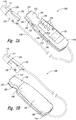
- FIGS 1A and 1B illustrate a clamp meter 100 according to an embodiment of the present invention.
- the clamp meter 100 includes a current clamp probe 110 that is detachable from a housing 112 in which circuitry for the clamp meter 100 are encased.
- the clamp probe 110 includes a current sensor for detecting current in a wire positioned in an opening 111. Examples of current sensors include Hall-effect devices and coils such as a current transformer, as known in the art.
- the clamp probe 110 is positioned in a recess 120 generally defined by clamp retention members 122, 126 that extend from a body 114.
- the clamp retention members 122, 126 have respective cutouts 124, 128 to expose a lever portion 130 of the clamp probe 110.
- the lever portion 130 When depressed, the lever portion 130 causes jaws of the clamp probe 110 to open to receive a wire in the opening 111 for measurement.
- the clamp probe 110 is a spring loaded device whereupon release of the lever portion 130, the clamp probe 110 will close. Consequently, when the wire is positioned in the opening 111, the lever portion 130 can be released to capture the wire for measurement. A wire can be released from the opening 111 by depressing the lever portion 130 and withdrawing the meter 100.
- each of the clamp retention members 122, 126 can optionally include a guide 118 for facilitating placement of the clamp probe 110 in the recess 120.
- the clamp probe 110 abuts the guide 118 when correctly positioned in the recess 120.
- the guide 118 can be further configured to keep the clamp probe 110 from moving when pressure is applied to the lever portion 130.
- the clamp retention members 122, 126 can include optional ridges 127 to provide tactile indicators of a known distance from the opening 111 when the clamp probe 110 is positioned in the recess 120.
- the clamp probe 110 can be retained by the clamp retention members 122, 126 using known techniques, such as an interference fit, snap fit, or the like, between the clamp probe 110 and the clamp retention members 122, 126.
- the technique used is sufficient to hold the clamp probe 110 in place when pressure is applied to the lever portion 130 while still allowing removal from the clamp retention members 122, 126.
- the user interface shown in Figure 1A includes a display 132 for displaying information, such as a measured value, mode of operation, and device and battery status.
- the user interface further includes buttons 134 that can be used to receive input from the user and carry out functions in the meter, for example, turning the meter on and off, selecting a mode of operation, selecting a measurement range, and taking a measurement.
- buttons 134 additional or alternative user input devices can be used in other embodiments, such as dials, thumb wheels, and switches. Additionally, the user input devices can be located at different positions than shown in Figure 1A .
- An optional light 140 can be included on the body 114 and positioned to provide illumination in the direction of the clamp probe 110 to aid in locating and clamping a wire in a darkened environment.
- the light 140 can use a conventional light source, such as a filament-based light source and a light emitting diode (“LED”) light source. Other types of light sources can be used as well.
- the light 140 can be designed to be switched on and off using one of the buttons 134.
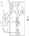
- FIG. 3 illustrates a simplified block diagram of electrical circuits that can be included in the clamp meter 100.
- the electrical circuits shown in Figure 3 are provided by way of example.
- the circuits included in the clamp meter 100 can be implemented in the meter 100 using conventional designs and operation.
- the clamp probe 110 is electrically coupled to a connector 310 through the wire 116. Electrical signals generated by the current sensor in the clamp probe 110 in response to detecting current in a wire positioned in the opening 111 are provided through the connector 310 to a signal conditioning circuit 320.
- the signal conditioning circuit 320 conditions the electrical signals, for example, by buffering, filtering, and amplifying the signal.
- a processor 330 receives the conditioned signal and computes a current measurement.
- the processor 330 generates signals to drive a liquid crystal display (“LCD”) 132 to display information, including the computed current value.
- LCD liquid crystal display
- an analog-to-digital converter is used to quantize the conditioned signal into digital information representing the conditioned signal prior to processing by the processor 330.
- Buttons 134 are provided for user input to the processor 330.
- a power supply 340 provides power to various circuitry of the meter 100, such as the signal conditioning circuit 320, the processor 330, and the LCD 132.
- the power supply 340 typically includes a battery and power circuits for regulating the provision of power to the circuits in the meter 100.
- the processor 330 is operable to compute measurements for other electrical characteristics, as detected by test probes coupled to electrical terminals (not shown) further included in the connector 310.
- multimeter functionality can be integrated into the meter 100, such as measuring voltage and resistance.
- the wire 116 can be neatly stowed to prevent tangling by wrapping the wire 116 around a rear portion 150.
- the rear portion is configured to form recesses 156 into which the wire 116 is received when wrapped.
- An optional groove 160 can be included in the body 114 for holding the wire 116 in place when wrapped around the rear portion 150 and the clamp probe 110 is positioned in the clamp retention members 122, 126.
- the rear portion 150 is removable to provide access to the electronics of the meter 100, such as for removal and installation of a battery or to allow for calibration.
- the rear portion 150 is integral with the rest of the housing 112.
- FIGS 2A and 2B illustrate the meter 100 with the clamp probe 110 detached from the housing 112 and the wire 116 fully deployed.
- the clamp probe 110 includes a ridge 129 to provide a tactile indicator of a known distance from the opening 111 when the clamp probe 110 is detached from the housing 112.
- the jaws of the clamp probe 110 can be opened by applying opposing pressure to the lever portion 130 and an opposite lever portion 131. As previously discussed, the clamp probe 110 is spring loaded, and upon release of the lever portion 130 and the opposite lever portion 131, the jaws of the clamp probe 110 will close.
- the meter 100 can be used with the clamp probe 110 positioned in the recess 120 or with the clamp probe 110 detached. Consequently, the convenience and functionality of the two conventionally configured clamp probe/meters are combined in one clamp meter.
- Figures 4A and 4B illustrate operation with the clamp probe 110 in place between the clamp retention members 122, 126.
- clamping a wire 410 and taking a measurement can be accomplished with one-handed operation.
- the clamp probe 110 can be operated by pressing the lever portion 130 using the thumb or a finger of one hand in order to clamp the wire 410.
- the lever portion 130 is released, as shown in Figure 4B , the clamp probe 110 captures the wire 410.
- buttons 134 can be pressed using the thumb or fingers of the same hand during measurement.
- One-handed operation is convenient for situations where the display 132 is viewable when the wire is clamped and the wire is easily accessible.
- FIG. 5 illustrates operation of the meter 100 with the clamp probe 110 detached.
- the clamp probe 110 With the clamp probe 110 detached from the housing 112 and the wire 116 unwrapped from the rear portion 150, the clamp probe 110 can be clamped to a wire 420 in an awkward location and the housing 112 positioned so that the display 132 is easily viewable. In this manner, it is unnecessary to remove the meter 100 from the clamped wire 420 after an initial measurement is taken, saving time and effort where subsequent measurements from the same wire are to be taken.
- the clamp probe 110 is illustrated as being slightly tapered to a "nose," which facilitates clamping of a wire that may be bundled with other wires.
- a clamp probe having more arcuate shaped jaws or having a larger opening can be used to accommodate larger diameter wires or used for applications where individual wires are sufficiently spaced and can be easily clamped.
- the option of taking a measurement with the clamp probe attached for one-handed operation or taking a measurement with the clamp probe detached is still desirable since the dual-use configuration allows the display to be conveniently positioned during measurement.
Landscapes
- Physics & Mathematics (AREA)
- General Physics & Mathematics (AREA)
- Engineering & Computer Science (AREA)
- Power Engineering (AREA)
- Measuring Instrument Details And Bridges, And Automatic Balancing Devices (AREA)
- Measurement Of Current Or Voltage (AREA)
Claims (15)
- Ampèremètre à pince ampèremétrique (100), comprenant :
un corps d'ampèremètre (114) et une pince ampèremétrique (110), le corps d'ampèremètre comprenant des circuits servant à calculer une mesure de courant provenant d'un signal d'entrée, la pince ampèremétrique étant couplée électriquement aux circuits par un fil métallique (116) et conçue pour détecter un courant et conçue pour fournir le signal d'entrée, ledit corps d'ampèremètre (114) et ladite pince ampèremétrique (110) étant conçus pour que la pince ampèremétrique (110) puisse être détachée du corps d'ampèremètre (114) et pour maintenir la fonctionnalité à travers le fil métallique (116) lorsque la pince ampèremétrique (110) est fixé au corps d'ampèremètre (114) et lorsque la pince ampèremétrique (110) est détachée du corps d'ampèremètre (114), et ledit corps d'ampèremètre (114) comprenant des premier et second éléments de retenue de pince (122, 126) qui s'étendent à partir du corps d'ampèremètre (114) et définissent une zone (120) entre eux dans laquelle la pince ampèremétrique est positionnée et retenue lorsque la pince ampèremétrique est fixée au corps d'ampèremètre. - Ampèremètre à pince ampèremétrique selon la revendication 1, ladite zone (120) dans laquelle la pince ampèremétrique (110) est positionnée lorsqu'elle est fixée au corps d'ampèremètre (114) étant conçue pour recevoir une partie de la pince ampèremétrique (110) dans une position fermée.
- Ampèremètre à pince ampèremétrique selon la revendication 1, ladite pince ampèremétrique (110) étant chargée par ressort de sorte que la libération d'une partie levier (130) de la pince ampèremétrique entraîne la fermeture de la pince ampèremétrique.
- Ampèremètre de revendication selon la revendication 1, lesdits premier et second éléments de retenue de pince (122, 126) possédant chacun une arête respective (127) formée sur ceux-ci à une distance prédéfinie à partir d'une ouverture de la pince ampèremétrique (110) lorsque la pince ampèremétrique est fixée au corps d'ampèremètre (114).
- Ampèremètre à pince ampèremétrique selon la revendication 1, ledit corps d'ampèremètre étant en outre conçu pour fournir une partie (150) autour de laquelle le fil métallique (166) peut être enroulé lorsque la pince ampèremétrique est fixée au corps d'ampèremètre.
- Ampèremètre à pince ampèremétrique selon la revendication 5, ladite partie du corps d'ampèremètre (114) autour de laquelle le fil métallique (116) est enroulé comprenant au moins un évidement (156) dans lequel le fil métallique est reçu lorsqu'il est enroulé.
- Ampèremètre à pince ampèremétrique selon la revendication 1, lesdits circuits compris dans le corps d'ampèremètre (114) comprenant un circuit de conditionnement de signal (320) conçu pour recevoir le signal d'entrée et un processeur (330) servant à calculer la mesure de courant.
- Ampèremètre à pince ampèremétrique selon la revendication 1, lesdits premier et second éléments de retenue de pince définissant au moins une découpe (124, 128) exposant une partie levier (130) de la pince ampèremétrique.
- Ampèremètre à pince ampèremétrique selon la revendication 1, chacun des premier et second éléments de retenue de pince (122, 126) possédant une surface intérieure sur laquelle un guide (118) est formé, la pince ampèremétrique (110) venant en butée contre le guide (118) lorsqu'elle est retenue par les premier et second éléments de retenue de pince.
- Ampèremètre à pince ampèremétrique selon la revendication 5, ladite partie autour de laquelle le fil métallique peut être enroulé comprenant une partie arrière du corps d'ampèremètre qui est conçue pour fournir au moins un évidement dans lequel le fil métallique est reçu lorsqu'il est enroulé.
- Ampèremètre à pince ampèremétrique selon la revendication 1, lesdits premier et second éléments de retenue de pince (122, 126) comprenant une partie qui vient en prise avec la pince ampèremétrique lorsque la pince ampèremétrique est fixée au corps d'ampèremètre.
- Ampèremètre à pince ampèremétrique selon la revendication 1, ladite pince ampèremétrique possédant un profil effilé.
- Procédé permettant de faire fonctionner un ampèremètre à pince ampèremétrique (100), comprenant :le détachement d'une sonde à pince ampèremétrique (110) fixée de manière amovible à un corps d'ampèremètre (114) de l'ampèremètre à pince ampèremétrique (100); ledit corps d'ampèremètre comprenant des circuits servant à calculer une mesure de courant à partir d'un signal d'entrée, la sonde à pince ampèremétrique étant électriquement couplée aux circuits par un fil métallique et conçu pour détecter un courant et pour fournir le signal d'entrée ;la fixation de la sonde de pince ampèremétrique (110) à un premier conducteur ;la mesure d'un premier courant dans le premier conducteur ;la fixation de nouveau de la sonde de pince ampèremétrique (110) au corps d'ampèremètre (114) de l'ampèremètre à pince ampèremétrique (100), ladite fixation de nouveau comprenant la disposition d'au moins une partie de la sonde de pince ampèremétrique (110) entre les éléments de retenue de pince (122, 126) du corps d'ampèremètre (114) ;la fixation de la sonde de pince ampèremétrique à un second conducteur pendant que la sonde de pince ampèremétrique (110) est fixée au corps d'ampèremètre (114) en appliquant une pression sur une partie exposée d'un levier (130) de la sonde de pince ampèremétrique pour ouvrir la sonde de pince ampèremétrique ; etla mesure d'un second courant dans le second conducteur.
- Procédé selon la revendication 13, ladite fixation de nouveau de la sonde de pince ampèremétrique au corps d'ampèremètre de l'ampèremètre à pince ampèremétrique comprenant en outre la mise en prise d'au moins une partie de la sonde de pince ampèremétrique avec les éléments de retenue de pince du corps d'ampèremètre.
- Procédé selon la revendication 13, ladite application d'une pression sur la partie exposée du levier comprenant l'enfoncement de la partie exposée à travers une découpe définie par les éléments de retenue de pince.
Applications Claiming Priority (2)
| Application Number | Priority Date | Filing Date | Title |
|---|---|---|---|
| US11/414,655 US7439726B2 (en) | 2006-04-27 | 2006-04-27 | Electrical measuring instrument having detachable current clamp probe |
| PCT/US2007/066519 WO2007127617A2 (fr) | 2006-04-27 | 2007-04-12 | Instrument de mesure électrique ayant une pince ampèremétrique détachable |
Publications (3)
| Publication Number | Publication Date |
|---|---|
| EP2016429A2 EP2016429A2 (fr) | 2009-01-21 |
| EP2016429A4 EP2016429A4 (fr) | 2017-07-12 |
| EP2016429B1 true EP2016429B1 (fr) | 2021-01-13 |
Family
ID=38647724
Family Applications (1)
| Application Number | Title | Priority Date | Filing Date |
|---|---|---|---|
| EP07760556.6A Active EP2016429B1 (fr) | 2006-04-27 | 2007-04-12 | Instrument de mesure électrique ayant une pince ampèremétrique détachable |
Country Status (7)
| Country | Link |
|---|---|
| US (3) | US7439726B2 (fr) |
| EP (1) | EP2016429B1 (fr) |
| JP (2) | JP5039778B2 (fr) |
| CN (1) | CN101467052A (fr) |
| BR (1) | BRPI0710766B1 (fr) |
| TW (1) | TWI329204B (fr) |
| WO (1) | WO2007127617A2 (fr) |
Families Citing this family (48)
| Publication number | Priority date | Publication date | Assignee | Title |
|---|---|---|---|---|
| US7851758B1 (en) | 2005-09-29 | 2010-12-14 | Flir Systems, Inc. | Portable multi-function inspection systems and methods |
| US7439726B2 (en) | 2006-04-27 | 2008-10-21 | Fluke Corporation | Electrical measuring instrument having detachable current clamp probe |
| US7557559B1 (en) * | 2006-06-19 | 2009-07-07 | Seektech, Inc. | Compact line illuminator for locating buried pipes and cables |
| FI121522B (fi) * | 2007-06-06 | 2010-12-15 | Abb Oy | Menetelmä taajuusmuuttajayksikön ohjaamiseksi ja taajuusmuuttajakokoonpano |
| US9383394B2 (en) | 2007-11-02 | 2016-07-05 | Cooper Technologies Company | Overhead communicating device |
| CA2717860C (fr) * | 2008-03-07 | 2016-11-08 | Milwaukee Electric Tool Corporation | Boitier de batterie pour une utilisation avec un outil motorise et un outil de detection non motorise |
| EP2275827B1 (fr) * | 2009-07-17 | 2025-03-19 | Fluke Corporation | Multimètres à fixation incluant une bobine de rogowski pour mesurer le courant alternatif dans un conducteur |
| US9615147B2 (en) | 2010-05-17 | 2017-04-04 | Flir Systems, Inc. | Multisensory meter system |
| US20110304319A1 (en) * | 2010-06-09 | 2011-12-15 | Brymen Technology Corporation | Multimeter with flexible current sensor |
| US20120020049A1 (en) * | 2010-07-22 | 2012-01-26 | Hsin-Chen Ko | Hook-type electric meter capable of providing light source |
| CN103250060A (zh) | 2010-08-10 | 2013-08-14 | 库柏技术公司 | 用于安装悬置装置的设备和方法 |
| CN102012447B (zh) * | 2010-10-12 | 2012-04-18 | 邢台供电公司 | 伸缩式钳形电流表 |
| CA2755468A1 (fr) * | 2010-10-18 | 2012-04-18 | Milwaukee Electric Tool Corporation | Compteur a pince amovible avec compartiment de stockage |
| JP5588319B2 (ja) * | 2010-11-24 | 2014-09-10 | 日置電機株式会社 | クランプ式測定器、及びクランプセンサ |
| CN102109565B (zh) * | 2010-12-20 | 2013-04-03 | 山东电力集团公司超高压公司 | Ct二次回路智能检测仪 |
| US8922195B2 (en) * | 2010-12-30 | 2014-12-30 | Fluke Corporation | Simplified jaw assembly for a clamp meter |
| USD683248S1 (en) * | 2012-01-27 | 2013-05-28 | Fluke Corporation | R-coil, temperature and voltage modules with wireless transmitter |
| US10095659B2 (en) * | 2012-08-03 | 2018-10-09 | Fluke Corporation | Handheld devices, systems, and methods for measuring parameters |
| CN103675359B (zh) * | 2012-09-11 | 2018-06-08 | 福禄克精密测量有限公司 | 用于电池测试仪的无线手柄及包含该手柄的电池测试仪组件 |
| JP6054710B2 (ja) * | 2012-11-08 | 2016-12-27 | 日置電機株式会社 | 接地抵抗計 |
| US9379556B2 (en) | 2013-03-14 | 2016-06-28 | Cooper Technologies Company | Systems and methods for energy harvesting and current and voltage measurements |
| CN105408898B (zh) | 2013-03-15 | 2019-05-28 | 弗兰克公司 | 测量数据的自动记录和图形生成 |
| US9188606B2 (en) | 2013-04-29 | 2015-11-17 | Keysight Technologies, Inc. | Oscilloscope current probe with interchangeable range and sensitivity setting modules |
| USD719040S1 (en) | 2013-07-12 | 2014-12-09 | Milwaukee Electric Tool Corporation | Electrical tester |
| USD724976S1 (en) | 2013-12-31 | 2015-03-24 | Milwaukee Electric Tool Corporation | Electrical tester |
| US9664708B2 (en) | 2014-01-09 | 2017-05-30 | Milwaukee Electric Tool Corporation | Test and measurement device including grooves for receiving probes in a use position |
| US9671433B2 (en) | 2014-04-25 | 2017-06-06 | Infineon Technologies Ag | Current sensor devices and methods |
| US9410933B2 (en) * | 2014-05-29 | 2016-08-09 | The United States of America a represented by the Secretary of Navy | Method and apparatus for determining the salinity of a sample |
| WO2016013021A1 (fr) * | 2014-07-25 | 2016-01-28 | Selec Controls Pvt. Ltd. | Ensemble transformateur de courant à adaptateur fonctionnel apte à être fixé |
| CN104297550A (zh) * | 2014-09-17 | 2015-01-21 | 国家电网公司 | 杆式钳形电流测量仪 |
| CN105510671B (zh) * | 2014-09-24 | 2020-10-30 | 福禄克公司 | 钳表及钳状探头 |
| JP6462320B2 (ja) * | 2014-11-10 | 2019-01-30 | 日置電機株式会社 | フレキシブルセンサおよび測定装置 |
| USD797107S1 (en) * | 2015-07-02 | 2017-09-12 | Datalogic Ip Tech S.R.L. | Portable terminal |
| CN205003199U (zh) * | 2015-09-02 | 2016-01-27 | 丹纳赫(上海)工业仪器技术研发有限公司 | 便携式测量装置 |
| US10228393B2 (en) * | 2016-02-15 | 2019-03-12 | Kane Usa, Inc. | Slide closure multi tester |
| US10267833B2 (en) * | 2016-11-02 | 2019-04-23 | Equinix, Inc. | Power monitoring probe for monitoring power distribution in an electrical system |
| JP6202461B1 (ja) | 2017-03-06 | 2017-09-27 | 株式会社シーブイエンジニアリング | 電流測定装置 |
| CN107576825B (zh) * | 2017-08-21 | 2024-01-30 | 贵州电网有限责任公司 | 一种变径直流、回路电阻测试夹 |
| US11513154B2 (en) * | 2018-08-31 | 2022-11-29 | Black & Decker Inc. | System and apparatus for monitoring the performance of an electrically powered device |
| JP7311261B2 (ja) * | 2018-11-09 | 2023-07-19 | 日置電機株式会社 | フレキシブルセンサ及び測定装置 |
| CN111474398A (zh) * | 2020-04-27 | 2020-07-31 | 南宁学院 | 一种便于携带和检测的万用表 |
| CN114280390B (zh) * | 2020-09-27 | 2024-12-03 | 安徽国润电力有限公司 | 一种电路故障用排查装置 |
| US11614470B2 (en) * | 2020-11-05 | 2023-03-28 | U-Haul International, Inc. | Non-invasive current sensing device |
| WO2022155613A1 (fr) * | 2021-01-15 | 2022-07-21 | Essenlix Corporation | Amélioration de la précision d'une analyse basée sur l'imagerie par apprentissage guidé |
| CN114563597B (zh) * | 2022-02-28 | 2025-02-28 | 广东电网有限责任公司 | 一种万能表 |
| CN114924107A (zh) * | 2022-05-13 | 2022-08-19 | 安徽科盟电子科技有限公司 | 一种无线钳形电流检测装置及其检测方法 |
| CN119256233A (zh) * | 2022-05-23 | 2025-01-03 | 理想工业公司 | 具有电路追踪器、插座测试器和/或负载连续性测试器的集成工具 |
| US20260063667A1 (en) * | 2024-08-30 | 2026-03-05 | Horizon Global Americas Inc. | Non-invasive wire testing device |
Family Cites Families (18)
| Publication number | Priority date | Publication date | Assignee | Title |
|---|---|---|---|---|
| US3555420A (en) * | 1967-09-06 | 1971-01-12 | Soss Mfg Co | Voltage testing instrument |
| US3840808A (en) | 1973-04-30 | 1974-10-08 | Tif Instr Inc | Clamp-on electrical meter |
| US4079314A (en) * | 1974-10-12 | 1978-03-14 | Woo Chul Jone | Pincette type multi-tester |
| US4259635A (en) * | 1979-06-08 | 1981-03-31 | Triplett William R | Electrical continuity and voltage testing device having a pair of probes spaced for insertion into an electrical socket |
| JPS5622964A (en) * | 1979-07-31 | 1981-03-04 | Matsushita Electric Works Ltd | Clamp meter |
| US4378525A (en) | 1980-09-18 | 1983-03-29 | Burdick Neal M | Method and apparatus for measuring a DC current in a wire without making a direct connection to the wire |
| US5170114A (en) * | 1991-09-11 | 1992-12-08 | Myron Zucker, Inc. | Harmonimeter input circuit and methods of constructing and utilizing same |
| JPH06242171A (ja) * | 1993-02-18 | 1994-09-02 | Yukio Goto | 漏電回路検出器 |
| US5477133A (en) * | 1993-07-29 | 1995-12-19 | Etcon Corporation | Device for measuring a wide range of voltages and for determining continuity using visual and tactile indicators |
| US6229315B1 (en) * | 1995-05-25 | 2001-05-08 | Stephen J. Briggs | Hand-held harmonics detector |
| US6043640A (en) * | 1997-10-29 | 2000-03-28 | Fluke Corporation | Multimeter with current sensor |
| WO2000024108A1 (fr) * | 1998-10-16 | 2000-04-27 | Century Mfg. Co. | Chargeur de batterie portable comportant un commutateur anti-inversion de polarite |
| US6137285A (en) * | 1998-11-30 | 2000-10-24 | Applied Power, Inc. | Electrical voltage tester |
| JP4618763B2 (ja) * | 2003-06-04 | 2011-01-26 | ミドリ安全株式会社 | クランプ型漏れ電流計 |
| US7242173B2 (en) * | 2004-08-31 | 2007-07-10 | Fluke Corporation | Combined test instrument probe and voltage detector |
| US7327133B2 (en) * | 2005-09-21 | 2008-02-05 | Universal Enterprises, Inc. | Current measuring device using hall sensors |
| US7530277B2 (en) * | 2006-01-30 | 2009-05-12 | Hioki Denki Kabushiki Kaisha | Measuring apparatus |
| US7439726B2 (en) | 2006-04-27 | 2008-10-21 | Fluke Corporation | Electrical measuring instrument having detachable current clamp probe |
-
2006
- 2006-04-27 US US11/414,655 patent/US7439726B2/en not_active Expired - Lifetime
-
2007
- 2007-04-12 EP EP07760556.6A patent/EP2016429B1/fr active Active
- 2007-04-12 WO PCT/US2007/066519 patent/WO2007127617A2/fr not_active Ceased
- 2007-04-12 JP JP2009507889A patent/JP5039778B2/ja active Active
- 2007-04-12 CN CNA2007800210510A patent/CN101467052A/zh active Pending
- 2007-04-12 BR BRPI0710766-8A patent/BRPI0710766B1/pt active IP Right Grant
- 2007-04-19 TW TW096113838A patent/TWI329204B/zh active
- 2007-05-25 US US11/753,852 patent/US7312603B2/en not_active Expired - Lifetime
-
2008
- 2008-10-20 US US12/254,765 patent/US7659710B2/en not_active Expired - Lifetime
-
2012
- 2012-05-31 JP JP2012124888A patent/JP5497847B2/ja active Active
Non-Patent Citations (1)
| Title |
|---|
| None * |
Also Published As
| Publication number | Publication date |
|---|---|
| WO2007127617A2 (fr) | 2007-11-08 |
| JP5497847B2 (ja) | 2014-05-21 |
| TW200745569A (en) | 2007-12-16 |
| US7659710B2 (en) | 2010-02-09 |
| JP5039778B2 (ja) | 2012-10-03 |
| BRPI0710766A2 (pt) | 2011-06-07 |
| CN101467052A (zh) | 2009-06-24 |
| EP2016429A2 (fr) | 2009-01-21 |
| US20090039870A1 (en) | 2009-02-12 |
| EP2016429A4 (fr) | 2017-07-12 |
| TWI329204B (en) | 2010-08-21 |
| US7312603B2 (en) | 2007-12-25 |
| US20070252579A1 (en) | 2007-11-01 |
| JP2012185176A (ja) | 2012-09-27 |
| WO2007127617A3 (fr) | 2008-10-09 |
| US7439726B2 (en) | 2008-10-21 |
| JP2009535623A (ja) | 2009-10-01 |
| US20070252578A1 (en) | 2007-11-01 |
| BRPI0710766B1 (pt) | 2018-07-10 |
Similar Documents
| Publication | Publication Date | Title |
|---|---|---|
| EP2016429B1 (fr) | Instrument de mesure électrique ayant une pince ampèremétrique détachable | |
| US8922195B2 (en) | Simplified jaw assembly for a clamp meter | |
| TWI799576B (zh) | 用於非接觸式電參數測量之夾鉗探針 | |
| US8201342B2 (en) | Baby scales | |
| US7109700B2 (en) | Multimeter having off-device display device and selection device | |
| EP3862762B1 (fr) | Mesure de tension sans contact à l'aide d'une bobine de rogowski de taille réglable | |
| EP4145141A1 (fr) | Sonde de capteur avec capteur sans contact et bobine de rogowski combinés | |
| EP2275827B1 (fr) | Multimètres à fixation incluant une bobine de rogowski pour mesurer le courant alternatif dans un conducteur | |
| US20050209810A1 (en) | Measuring instrument with sensors | |
| EP3862761B1 (fr) | Sonde de capteur avec pince dotée d'une région intérieure réglable de mesure électrique sans contact | |
| JP2007303952A (ja) | 電流測定装置 | |
| US20180038893A1 (en) | Slide closure multi tester | |
| JPH0634691Y2 (ja) | 計測器の端子装置 | |
| CN113125836A (zh) | 一种电流探头 | |
| KR20000018039A (ko) | 전압 및 전류 표시기를 갖는 케이블장치 |
Legal Events
| Date | Code | Title | Description |
|---|---|---|---|
| PUAI | Public reference made under article 153(3) epc to a published international application that has entered the european phase |
Free format text: ORIGINAL CODE: 0009012 |
|
| 17P | Request for examination filed |
Effective date: 20081121 |
|
| AK | Designated contracting states |
Kind code of ref document: A2 Designated state(s): AT BE BG CH CY CZ DE DK EE ES FI FR GB GR HU IE IS IT LI LT LU LV MC MT NL PL PT RO SE SI SK TR |
|
| AX | Request for extension of the european patent |
Extension state: AL BA HR MK RS |
|
| DAX | Request for extension of the european patent (deleted) | ||
| RIN1 | Information on inventor provided before grant (corrected) |
Inventor name: YONG,WANG Inventor name: LUO, SHOUNAN |
|
| A4 | Supplementary search report drawn up and despatched |
Effective date: 20170614 |
|
| RIC1 | Information provided on ipc code assigned before grant |
Ipc: G01R 1/067 20060101AFI20170606BHEP Ipc: G01R 1/04 20060101ALN20170606BHEP Ipc: G01R 15/18 20060101ALN20170606BHEP Ipc: G01R 1/22 20060101ALI20170606BHEP |
|
| GRAJ | Information related to disapproval of communication of intention to grant by the applicant or resumption of examination proceedings by the epo deleted |
Free format text: ORIGINAL CODE: EPIDOSDIGR1 |
|
| STAA | Information on the status of an ep patent application or granted ep patent |
Free format text: STATUS: GRANT OF PATENT IS INTENDED |
|
| GRAP | Despatch of communication of intention to grant a patent |
Free format text: ORIGINAL CODE: EPIDOSNIGR1 |
|
| RIC1 | Information provided on ipc code assigned before grant |
Ipc: G01R 1/22 20060101ALI20200519BHEP Ipc: G01R 1/04 20060101ALN20200519BHEP Ipc: G01R 15/18 20060101ALN20200519BHEP Ipc: G01R 1/067 20060101AFI20200519BHEP |
|
| INTG | Intention to grant announced |
Effective date: 20200610 |
|
| GRAJ | Information related to disapproval of communication of intention to grant by the applicant or resumption of examination proceedings by the epo deleted |
Free format text: ORIGINAL CODE: EPIDOSDIGR1 |
|
| STAA | Information on the status of an ep patent application or granted ep patent |
Free format text: STATUS: REQUEST FOR EXAMINATION WAS MADE |
|
| INTC | Intention to grant announced (deleted) | ||
| REG | Reference to a national code |
Ref country code: DE Ref legal event code: R079 Ref document number: 602007060900 Country of ref document: DE Free format text: PREVIOUS MAIN CLASS: G01R0015180000 Ipc: G01R0001067000 |
|
| GRAR | Information related to intention to grant a patent recorded |
Free format text: ORIGINAL CODE: EPIDOSNIGR71 |
|
| GRAS | Grant fee paid |
Free format text: ORIGINAL CODE: EPIDOSNIGR3 |
|
| STAA | Information on the status of an ep patent application or granted ep patent |
Free format text: STATUS: GRANT OF PATENT IS INTENDED |
|
| GRAA | (expected) grant |
Free format text: ORIGINAL CODE: 0009210 |
|
| STAA | Information on the status of an ep patent application or granted ep patent |
Free format text: STATUS: THE PATENT HAS BEEN GRANTED |
|
| RIC1 | Information provided on ipc code assigned before grant |
Ipc: G01R 1/04 20060101ALN20201116BHEP Ipc: G01R 1/22 20060101ALI20201116BHEP Ipc: G01R 1/067 20060101AFI20201116BHEP Ipc: G01R 15/18 20060101ALN20201116BHEP |
|
| RIC1 | Information provided on ipc code assigned before grant |
Ipc: G01R 1/04 20060101ALN20201120BHEP Ipc: G01R 15/18 20060101ALN20201120BHEP Ipc: G01R 1/22 20060101ALI20201120BHEP Ipc: G01R 1/067 20060101AFI20201120BHEP |
|
| INTG | Intention to grant announced |
Effective date: 20201202 |
|
| RIC1 | Information provided on ipc code assigned before grant |
Ipc: G01R 15/18 20060101ALN20201201BHEP Ipc: G01R 1/04 20060101ALN20201201BHEP Ipc: G01R 1/22 20060101ALI20201201BHEP Ipc: G01R 1/067 20060101AFI20201201BHEP |
|
| AK | Designated contracting states |
Kind code of ref document: B1 Designated state(s): AT BE BG CH CY CZ DE DK EE ES FI FR GB GR HU IE IS IT LI LT LU LV MC MT NL PL PT RO SE SI SK TR |
|
| REG | Reference to a national code |
Ref country code: GB Ref legal event code: FG4D |
|
| REG | Reference to a national code |
Ref country code: CH Ref legal event code: EP |
|
| REG | Reference to a national code |
Ref country code: IE Ref legal event code: FG4D |
|
| REG | Reference to a national code |
Ref country code: DE Ref legal event code: R096 Ref document number: 602007060900 Country of ref document: DE |
|
| REG | Reference to a national code |
Ref country code: AT Ref legal event code: REF Ref document number: 1353802 Country of ref document: AT Kind code of ref document: T Effective date: 20210215 |
|
| REG | Reference to a national code |
Ref country code: AT Ref legal event code: MK05 Ref document number: 1353802 Country of ref document: AT Kind code of ref document: T Effective date: 20210113 |
|
| REG | Reference to a national code |
Ref country code: NL Ref legal event code: MP Effective date: 20210113 |
|
| REG | Reference to a national code |
Ref country code: LT Ref legal event code: MG9D |
|
| PG25 | Lapsed in a contracting state [announced via postgrant information from national office to epo] |
Ref country code: GR Free format text: LAPSE BECAUSE OF FAILURE TO SUBMIT A TRANSLATION OF THE DESCRIPTION OR TO PAY THE FEE WITHIN THE PRESCRIBED TIME-LIMIT Effective date: 20210414 Ref country code: FI Free format text: LAPSE BECAUSE OF FAILURE TO SUBMIT A TRANSLATION OF THE DESCRIPTION OR TO PAY THE FEE WITHIN THE PRESCRIBED TIME-LIMIT Effective date: 20210113 Ref country code: LT Free format text: LAPSE BECAUSE OF FAILURE TO SUBMIT A TRANSLATION OF THE DESCRIPTION OR TO PAY THE FEE WITHIN THE PRESCRIBED TIME-LIMIT Effective date: 20210113 Ref country code: BG Free format text: LAPSE BECAUSE OF FAILURE TO SUBMIT A TRANSLATION OF THE DESCRIPTION OR TO PAY THE FEE WITHIN THE PRESCRIBED TIME-LIMIT Effective date: 20210413 Ref country code: NL Free format text: LAPSE BECAUSE OF FAILURE TO SUBMIT A TRANSLATION OF THE DESCRIPTION OR TO PAY THE FEE WITHIN THE PRESCRIBED TIME-LIMIT Effective date: 20210113 Ref country code: PT Free format text: LAPSE BECAUSE OF FAILURE TO SUBMIT A TRANSLATION OF THE DESCRIPTION OR TO PAY THE FEE WITHIN THE PRESCRIBED TIME-LIMIT Effective date: 20210513 |
|
| PG25 | Lapsed in a contracting state [announced via postgrant information from national office to epo] |
Ref country code: SE Free format text: LAPSE BECAUSE OF FAILURE TO SUBMIT A TRANSLATION OF THE DESCRIPTION OR TO PAY THE FEE WITHIN THE PRESCRIBED TIME-LIMIT Effective date: 20210113 Ref country code: AT Free format text: LAPSE BECAUSE OF FAILURE TO SUBMIT A TRANSLATION OF THE DESCRIPTION OR TO PAY THE FEE WITHIN THE PRESCRIBED TIME-LIMIT Effective date: 20210113 Ref country code: LV Free format text: LAPSE BECAUSE OF FAILURE TO SUBMIT A TRANSLATION OF THE DESCRIPTION OR TO PAY THE FEE WITHIN THE PRESCRIBED TIME-LIMIT Effective date: 20210113 Ref country code: PL Free format text: LAPSE BECAUSE OF FAILURE TO SUBMIT A TRANSLATION OF THE DESCRIPTION OR TO PAY THE FEE WITHIN THE PRESCRIBED TIME-LIMIT Effective date: 20210113 |
|
| PG25 | Lapsed in a contracting state [announced via postgrant information from national office to epo] |
Ref country code: IS Free format text: LAPSE BECAUSE OF FAILURE TO SUBMIT A TRANSLATION OF THE DESCRIPTION OR TO PAY THE FEE WITHIN THE PRESCRIBED TIME-LIMIT Effective date: 20210513 |
|
| REG | Reference to a national code |
Ref country code: DE Ref legal event code: R097 Ref document number: 602007060900 Country of ref document: DE |
|
| PG25 | Lapsed in a contracting state [announced via postgrant information from national office to epo] |
Ref country code: CZ Free format text: LAPSE BECAUSE OF FAILURE TO SUBMIT A TRANSLATION OF THE DESCRIPTION OR TO PAY THE FEE WITHIN THE PRESCRIBED TIME-LIMIT Effective date: 20210113 Ref country code: EE Free format text: LAPSE BECAUSE OF FAILURE TO SUBMIT A TRANSLATION OF THE DESCRIPTION OR TO PAY THE FEE WITHIN THE PRESCRIBED TIME-LIMIT Effective date: 20210113 |
|
| PLBE | No opposition filed within time limit |
Free format text: ORIGINAL CODE: 0009261 |
|
| STAA | Information on the status of an ep patent application or granted ep patent |
Free format text: STATUS: NO OPPOSITION FILED WITHIN TIME LIMIT |
|
| PG25 | Lapsed in a contracting state [announced via postgrant information from national office to epo] |
Ref country code: RO Free format text: LAPSE BECAUSE OF FAILURE TO SUBMIT A TRANSLATION OF THE DESCRIPTION OR TO PAY THE FEE WITHIN THE PRESCRIBED TIME-LIMIT Effective date: 20210113 Ref country code: SK Free format text: LAPSE BECAUSE OF FAILURE TO SUBMIT A TRANSLATION OF THE DESCRIPTION OR TO PAY THE FEE WITHIN THE PRESCRIBED TIME-LIMIT Effective date: 20210113 Ref country code: MC Free format text: LAPSE BECAUSE OF FAILURE TO SUBMIT A TRANSLATION OF THE DESCRIPTION OR TO PAY THE FEE WITHIN THE PRESCRIBED TIME-LIMIT Effective date: 20210113 Ref country code: DK Free format text: LAPSE BECAUSE OF FAILURE TO SUBMIT A TRANSLATION OF THE DESCRIPTION OR TO PAY THE FEE WITHIN THE PRESCRIBED TIME-LIMIT Effective date: 20210113 Ref country code: ES Free format text: LAPSE BECAUSE OF FAILURE TO SUBMIT A TRANSLATION OF THE DESCRIPTION OR TO PAY THE FEE WITHIN THE PRESCRIBED TIME-LIMIT Effective date: 20210113 |
|
| 26N | No opposition filed |
Effective date: 20211014 |
|
| PG25 | Lapsed in a contracting state [announced via postgrant information from national office to epo] |
Ref country code: LU Free format text: LAPSE BECAUSE OF NON-PAYMENT OF DUE FEES Effective date: 20210412 |
|
| REG | Reference to a national code |
Ref country code: BE Ref legal event code: MM Effective date: 20210430 |
|
| PG25 | Lapsed in a contracting state [announced via postgrant information from national office to epo] |
Ref country code: CH Free format text: LAPSE BECAUSE OF NON-PAYMENT OF DUE FEES Effective date: 20210430 Ref country code: LI Free format text: LAPSE BECAUSE OF NON-PAYMENT OF DUE FEES Effective date: 20210430 |
|
| PG25 | Lapsed in a contracting state [announced via postgrant information from national office to epo] |
Ref country code: SI Free format text: LAPSE BECAUSE OF FAILURE TO SUBMIT A TRANSLATION OF THE DESCRIPTION OR TO PAY THE FEE WITHIN THE PRESCRIBED TIME-LIMIT Effective date: 20210113 |
|
| PG25 | Lapsed in a contracting state [announced via postgrant information from national office to epo] |
Ref country code: IT Free format text: LAPSE BECAUSE OF FAILURE TO SUBMIT A TRANSLATION OF THE DESCRIPTION OR TO PAY THE FEE WITHIN THE PRESCRIBED TIME-LIMIT Effective date: 20210113 Ref country code: IE Free format text: LAPSE BECAUSE OF NON-PAYMENT OF DUE FEES Effective date: 20210412 |
|
| PG25 | Lapsed in a contracting state [announced via postgrant information from national office to epo] |
Ref country code: IS Free format text: LAPSE BECAUSE OF FAILURE TO SUBMIT A TRANSLATION OF THE DESCRIPTION OR TO PAY THE FEE WITHIN THE PRESCRIBED TIME-LIMIT Effective date: 20210513 |
|
| PG25 | Lapsed in a contracting state [announced via postgrant information from national office to epo] |
Ref country code: BE Free format text: LAPSE BECAUSE OF NON-PAYMENT OF DUE FEES Effective date: 20210430 |
|
| PG25 | Lapsed in a contracting state [announced via postgrant information from national office to epo] |
Ref country code: HU Free format text: LAPSE BECAUSE OF FAILURE TO SUBMIT A TRANSLATION OF THE DESCRIPTION OR TO PAY THE FEE WITHIN THE PRESCRIBED TIME-LIMIT; INVALID AB INITIO Effective date: 20070412 Ref country code: CY Free format text: LAPSE BECAUSE OF FAILURE TO SUBMIT A TRANSLATION OF THE DESCRIPTION OR TO PAY THE FEE WITHIN THE PRESCRIBED TIME-LIMIT Effective date: 20210113 |
|
| PG25 | Lapsed in a contracting state [announced via postgrant information from national office to epo] |
Ref country code: TR Free format text: LAPSE BECAUSE OF FAILURE TO SUBMIT A TRANSLATION OF THE DESCRIPTION OR TO PAY THE FEE WITHIN THE PRESCRIBED TIME-LIMIT Effective date: 20210113 |
|
| PG25 | Lapsed in a contracting state [announced via postgrant information from national office to epo] |
Ref country code: MT Free format text: LAPSE BECAUSE OF FAILURE TO SUBMIT A TRANSLATION OF THE DESCRIPTION OR TO PAY THE FEE WITHIN THE PRESCRIBED TIME-LIMIT Effective date: 20210113 |
|
| PGFP | Annual fee paid to national office [announced via postgrant information from national office to epo] |
Ref country code: DE Payment date: 20250428 Year of fee payment: 19 |
|
| PGFP | Annual fee paid to national office [announced via postgrant information from national office to epo] |
Ref country code: GB Payment date: 20250422 Year of fee payment: 19 |
|
| PGFP | Annual fee paid to national office [announced via postgrant information from national office to epo] |
Ref country code: FR Payment date: 20250424 Year of fee payment: 19 |