EP2016843A1 - Pièce de vêtement dotée d'un dispositif d'aération pour un corps humain - Google Patents
Pièce de vêtement dotée d'un dispositif d'aération pour un corps humain Download PDFInfo
- Publication number
- EP2016843A1 EP2016843A1 EP08009546A EP08009546A EP2016843A1 EP 2016843 A1 EP2016843 A1 EP 2016843A1 EP 08009546 A EP08009546 A EP 08009546A EP 08009546 A EP08009546 A EP 08009546A EP 2016843 A1 EP2016843 A1 EP 2016843A1
- Authority
- EP
- European Patent Office
- Prior art keywords
- channels
- air
- garment according
- garment
- support frame
- Prior art date
- Legal status (The legal status is an assumption and is not a legal conclusion. Google has not performed a legal analysis and makes no representation as to the accuracy of the status listed.)
- Granted
Links
- 238000009423 ventilation Methods 0.000 title claims abstract description 18
- 210000003734 kidney Anatomy 0.000 claims description 12
- 239000004744 fabric Substances 0.000 claims description 10
- 229910000831 Steel Inorganic materials 0.000 claims description 9
- 239000006261 foam material Substances 0.000 claims description 9
- 239000010959 steel Substances 0.000 claims description 9
- WYTGDNHDOZPMIW-RCBQFDQVSA-N alstonine Natural products C1=CC2=C3C=CC=CC3=NC2=C2N1C[C@H]1[C@H](C)OC=C(C(=O)OC)[C@H]1C2 WYTGDNHDOZPMIW-RCBQFDQVSA-N 0.000 claims description 4
- 230000001012 protector Effects 0.000 claims description 2
- 238000005086 pumping Methods 0.000 claims description 2
- 210000004072 lung Anatomy 0.000 description 10
- 239000006260 foam Substances 0.000 description 8
- 238000000034 method Methods 0.000 description 7
- 239000000463 material Substances 0.000 description 6
- 229910000639 Spring steel Inorganic materials 0.000 description 5
- 239000004033 plastic Substances 0.000 description 5
- 229920003023 plastic Polymers 0.000 description 5
- 238000010248 power generation Methods 0.000 description 5
- 210000004243 sweat Anatomy 0.000 description 5
- 230000001681 protective effect Effects 0.000 description 4
- XLYOFNOQVPJJNP-UHFFFAOYSA-N water Substances O XLYOFNOQVPJJNP-UHFFFAOYSA-N 0.000 description 4
- 238000003466 welding Methods 0.000 description 4
- 230000006978 adaptation Effects 0.000 description 3
- 238000005452 bending Methods 0.000 description 3
- 238000013016 damping Methods 0.000 description 3
- 238000000465 moulding Methods 0.000 description 3
- 241000238631 Hexapoda Species 0.000 description 2
- 238000005273 aeration Methods 0.000 description 2
- 230000000845 anti-microbial effect Effects 0.000 description 2
- 229920003235 aromatic polyamide Polymers 0.000 description 2
- 238000000748 compression moulding Methods 0.000 description 2
- 230000000694 effects Effects 0.000 description 2
- 230000005611 electricity Effects 0.000 description 2
- 230000009970 fire resistant effect Effects 0.000 description 2
- 238000001746 injection moulding Methods 0.000 description 2
- 239000000126 substance Substances 0.000 description 2
- 239000004753 textile Substances 0.000 description 2
- 241000282412 Homo Species 0.000 description 1
- 239000004952 Polyamide Substances 0.000 description 1
- 239000006096 absorbing agent Substances 0.000 description 1
- 239000000853 adhesive Substances 0.000 description 1
- 230000001070 adhesive effect Effects 0.000 description 1
- 239000004760 aramid Substances 0.000 description 1
- 230000002146 bilateral effect Effects 0.000 description 1
- 230000015572 biosynthetic process Effects 0.000 description 1
- 238000007664 blowing Methods 0.000 description 1
- 150000001875 compounds Chemical class 0.000 description 1
- 238000001816 cooling Methods 0.000 description 1
- 201000010099 disease Diseases 0.000 description 1
- 208000037265 diseases, disorders, signs and symptoms Diseases 0.000 description 1
- 238000001035 drying Methods 0.000 description 1
- 239000007789 gas Substances 0.000 description 1
- 210000004392 genitalia Anatomy 0.000 description 1
- 238000010438 heat treatment Methods 0.000 description 1
- 238000010348 incorporation Methods 0.000 description 1
- 238000002347 injection Methods 0.000 description 1
- 239000007924 injection Substances 0.000 description 1
- 208000014674 injury Diseases 0.000 description 1
- 239000000615 nonconductor Substances 0.000 description 1
- 229920002647 polyamide Polymers 0.000 description 1
- 229920000098 polyolefin Polymers 0.000 description 1
- 239000011148 porous material Substances 0.000 description 1
- 230000008092 positive effect Effects 0.000 description 1
- 230000001105 regulatory effect Effects 0.000 description 1
- 230000035939 shock Effects 0.000 description 1
- 125000006850 spacer group Chemical group 0.000 description 1
- 210000000106 sweat gland Anatomy 0.000 description 1
- 239000002341 toxic gas Substances 0.000 description 1
- 230000008733 trauma Effects 0.000 description 1
Images


Classifications
-
- F—MECHANICAL ENGINEERING; LIGHTING; HEATING; WEAPONS; BLASTING
- F41—WEAPONS
- F41H—ARMOUR; ARMOURED TURRETS; ARMOURED OR ARMED VEHICLES; MEANS OF ATTACK OR DEFENCE, e.g. CAMOUFLAGE, IN GENERAL
- F41H1/00—Personal protection gear
- F41H1/02—Armoured or projectile- or missile-resistant garments; Composite protection fabrics
-
- A—HUMAN NECESSITIES
- A41—WEARING APPAREL
- A41D—OUTERWEAR; PROTECTIVE GARMENTS; ACCESSORIES
- A41D13/00—Professional, industrial or sporting protective garments, e.g. surgeons' gowns or garments protecting against blows or punches
- A41D13/002—Professional, industrial or sporting protective garments, e.g. surgeons' gowns or garments protecting against blows or punches with controlled internal environment
- A41D13/0025—Professional, industrial or sporting protective garments, e.g. surgeons' gowns or garments protecting against blows or punches with controlled internal environment by means of forced air circulation
Definitions
- the invention relates to clothing for the ventilation of a human body according to the preamble of claim 1.
- a person has typical areas of sweat, especially in the chest area adjacent to the neck, under the armpits, in the back area adjacent to the neck and the neck area.
- a garment comprising ducts for the passage of air to specifically ventilate typical welding zones and to exclude other parts of the body from such ventilation.
- a ventilation in the kidney area is undesirable, since a ventilation can cause a disease here.
- the garment is preferably an outer garment, such as a T-shirt or a jacket.
- the ventilation device in the form of one, preferably two separate Inlets (Rückeninlet and Houseinlet) or as part of protectors are introduced into the clothing with.
- Rückeninlet and Houseinlet separate Inlets
- the ventilation system for the chest area and for the back area differs due to the different surfaces, the ergonomics and the respective medical concerns (arrangement of the sweat glands).
- the course of channels is chosen in particular so that the above-mentioned typical welding zones are ventilated. By this is meant that both moisture and heat from these zones are transported away via the channels.
- the course of the channels is provided in particular in such a way that sensible areas in humans, in particular the area of the kidney, are excluded from such aeration.
- the area of the lungs is too sensitive, even if this area is not as sensitive as the kidney area. Therefore, the area of the lungs may be exempt from aeration.
- the channels are designed so that the area of the lung is also ventilated, but comparatively weak.
- the item of clothing preferably comprises channels which transport air from top to bottom through the areas which are to be ventilated.
- the air is guided along the body via preferably serpentine channels so that a clearly positive effect in the form of rapid drying of the clothing and cooling is also achieved at the lower outlet opening in the region of the pants.
- the exact position of a fan that can be used to generate the air flow as well as the position of the pressure injection duct depends on the respective area of application.
- drive means are provided to transport the air through the channels, and in particular either to aspirate or pump, preferably to pump from top to bottom, but of course it is also possible, as seen from below, to pump upwards. Below is the area of a garment that is at the bottom when the garment is worn in an upright position as intended becomes. Above is the area of a garment that is at the top when the garment is worn in an upright position as intended.
- a drive means is in particular a fan or a pump. The drive means can be operated mechanically or electrically.
- the channel there are only one channel at the front and rear, via which fresh air is transported in and out again.
- the channel divides into two or more channels, which are preferably recombined prior to exit.
- the item of clothing is part of an ABC protective suit for soldiers, then the entry and exit areas are advantageously minimized, which are to be provided with an ABC filter. The need for, for example, protective grids that protect against the ingress of insects is kept so low.
- the channels are guided in an outer garment over the entire upper body in the form of interlaced serpentine, which can be adapted to the individual circumstances.
- a channel in front and a channel behind each is guided from bottom to top, if necessary, the channels can also run in the middle.
- the front is the area of a garment, the is on the side of the chest area of a human being when the item of clothing is worn in a proper manner in an upright, straight posture.
- this is the area of a garment which is on the side of the back of a person when the garment is worn in an upright manner in an upright position.
- the dimensions of the channels should be selected so that a high air flow with the lowest possible internal resistance can be achieved. Typical sweat zones in the chest and back area are thus particularly well ventilated.
- a channel is defined as having an immediate entry of fresh air. This makes it possible to connect the channels in an easy-to-handle manner, in particular with a blowing or pumping device, but also with a suction device or to separate such a device from the channels. If it is possible to connect such a device to the channels or to separate from these, so there is above all the advantage of being able to wash the garment without thereby damaging other mechanical or electrical devices that are responsible for the drive or air transport through the channels through.
- the kidney Since, above all, the kidney is susceptible, especially the area of the garment that is attached to the Kidney, when the garment is worn in a designated manner, is adjacent to channels through which air is transported. The kidney is thus protected from drafts for health reasons. In particular, in this case, a channel is passed between the two kidneys in front and behind, so to speak. There are no further left and right channels for the transport of air.
- Secondary channels are channels that open into a channel that has an immediate entry and exit of fresh air. When air is transported through a duct that has direct entry and exit of fresh air, it creates a suction effect that draws air out of the secondary ducts. Since the secondary channels have no direct entry for fresh air, only limited air can be transported through the secondary channels. However, a certain amount of air is transported because the secondary channels are not completely impermeable to air at least towards the body. In this way it is achieved that lung areas and especially the corresponding chest areas are ventilated a little without endangering the lungs. Under the area of the lung or under the chest area of the garment is the Region of the garment, which is adjacent to the chest or to a lung area of the body, when the garment is worn in a designated manner.
- the channels may be open to the body.
- the body or underwear then forms, as it were, a wall of the channel when the garment is worn as intended.
- the channels are covered by an air-permeable fabric towards the body when the garment is worn as intended.
- This air-permeable, preferably hydrophilic fabric causes underwear not to be pressed into the channels, for example due to wrinkling, which would hinder air circulation.
- the air-permeable fabric is preferably mounted so that the air-permeable fabric biased the channels to the body shields.
- the bias further ensures that the channels are kept clear, which maintains the air transport.
- the hydrophilic substance causes the sweat to be readily absorbed and transported to the air ducts at the points of the ventilation unit to which no channels are attached, and the moisture is conducted outward therefrom.
- the channels themselves are preferably formed by a material consisting of foam.
- Foam is on the one hand sufficiently light and on the other hand sufficiently dimensionally stable in order to provide channel structures can.
- the foam material may be open-pored to aid in the access of fresh air through the foam material. In the military sector, however, closed pores are to be preferred in order to protect a soldier from harmful gases.
- Foams made of polyolefin are preferred. These are flexible, but have a three-dimensional structure, if they have been prepared accordingly.
- the material has good chemical resistance, can be thermoformed and advantageously constitutes an electrical insulator.
- the foam may have hydrophilic and / or antimicrobial and / or fire-resistant properties.
- the foam in combination with ballistic purposes significantly reduces trauma.
- the provision of channel structures can be easily accomplished by a thermal molding process. A given shape is heated for this purpose, for example. A layer of foam material is placed on the mold. If the foam material reaches a softening point as a result of the heating, air is sucked through the predetermined shape. The foam material is thereby sucked into the mold. If it is then cooled again, the foam material solidifies again and there is the desired channel structure.
- the garment is basically made of a relatively stiff material, such as a foam material, in comparison to fabrics.
- the wearing comfort of such a garment is correspondingly lower.
- the garment has wavy structures in areas that are free of channel structures.
- it is the area of a garment that covers the kidney areas of the human and is therefore kept free of channels in principle.
- the troughs and crests then run vertically when the garment is worn in an upright position in the intended manner. It has been found that this improves the comfort.
- the channels in one embodiment have elevations that serve as spacers.
- the elevations are arranged so that a distance between the body of a human and a channel wall arranged parallel thereto is maintained. Proper, trouble-free air transport through the channels is thus further improved.
- the depth of the channels seen from the body is preferably at least 3 mm, preferably 12 mm. From this depth it is ensured that even by bending the garment channels are not clogged. It is then particularly well ensured that air can be pumped through or sucked through channels.
- the channels are several centimeters wide and in particular at least 1 cm and a maximum of 10 cm. Used foam material is preferably 2 to 10 mm thick.
- the drive means which actively effect the transport of air through the channels, are housed in a support frame.
- the support frame comprises in particular means for the operation of the drive means.
- Such a device for the operation of the drive means is in one embodiment of the invention, a battery.
- the drive means are electrically operated, so for example fans, which comprise an electric motor.
- the support frame may be such that the kinetic energy generated during walking or walking by a person wearing the clothing and the frame is converted into electrical energy. The energy is then used for the operation of the drive means.
- the drive means so for example a fan, is operated by means of batteries, solar panels or the like.
- the fan is connected via one or more hoses with the opening (or the inlet) of the channels, it should be noted that the hose, the air flow, for example, by kinking not negatively affected.
- the one or more hoses are plugged, for example, to the pressure channel or suction or to multiple pressure channels or suction channels.
- Such a device for the operation of the drive means may be solar cells in a further embodiment.
- the rotational speed of the fans used as drive means can be regulated. This ensures that individually, for example, front and back of the garment with the channels a separate ventilation level can be adjusted. Therefore, two fans are to be preferred, which can be controlled separately.
- the relative movement that a person makes while walking takes place between the hips and upper body.
- a relative movement of up to 12 cm is generated.
- Design of the support frame laterally mounted rods which have a mounting point above the waist when the support frame when the support frame is worn in the designated manner.
- lateral is understood that are located on the left and right of a person's body, when the frame is carried in a way intended by a human.
- These rods are inserted into tubes placed below the waist in the hip area are when the support frame is worn in the designated manner.
- the tubes are provided with coils.
- the rods are provided with magnets.
- the rod may also comprise a coil and the tube may be suitably provided with a permanent magnet.
- the tube may also be mounted above the hip on the support frame and the rod may be attached below the waist on the support frame.
- the bars comprise springs or else the bars are formed by springs. As a result, it is achieved in a simple manner that a bending movement is not hindered greatly by the rods.
- the support frame is designed in one embodiment so that the rear and / or front mounted a load and can be worn. So that body movements do not result in such a supported and moved load being transmitted directly to the body, in one embodiment the bars comprise springs of such a nature that a moving, supported load passes forces via the springs to a waist strap of the support frame. The springs dampen the transmitted forces comparable to a shock absorber. This increases the wearing comfort when carrying a load. Furthermore, will achieved by these damping springs that even current is generated.
- the support frame is designed so that a load is worn front and rear. This ensures that the load can be supported evenly on a hip belt. This further increases the wearing comfort.
- the support frame on a front and a rear stiff, preferably shield-shaped area adjacent to the upper body during wear.
- the two rigid areas which act like a shield, are connected to each other via one or more spring steels preferably over the shoulders.
- the rear rigid region has means, for example projecting webs, with which the load or the force generated thereby is transmitted to a hip belt or hip belt. These projecting webs are in particular connected to said rods, which are used for power generation.
- the front rigid area is at least initially connected only via the spring or the steel with the rest of the support frame.
- the front part in one embodiment folds forward and essentially forms a flat surface with the back part. This ensures that a load that is worn on the front, is passed through the rear part of the hip belt.
- the rear rigid region laterally projecting hinged webs, which are connected via said rods for power generation or the said tubes for generating electricity with a hip belt of the support frame.
- the rods are hinged because of hinges that connect the bars to the rear rigid area. It is achieved so that the protruding webs can be adapted to different body sizes. This increases the wearing comfort of the support frame.
- the spring steels are connected to the front or rear with a quick release with a rigid portion of the support frame.
- the quick release front is provided. This is designed so that the lock can be unlocked by a simple handle. This has the consequence that the front and rear stiff area falls down as soon as the unlocking is made. A soldier can be like that very quickly, for example in case of danger of a load.
- the two rigid areas are connected to each other only via one or more spring steels or a comparatively acting connecting means.
- a spring steel used in the aforementioned manner in one embodiment of the invention, a sheath made of plastic.
- This plastic material is provided at one of its ends with locking grooves. These locking grooves can be pushed into a corresponding recess and fixed at different locations. In this way, an improved adaptation of the support frame to different body sizes is possible.
- the support frame has one or more pressure channels or intake channels. Into this tubes are plugged in, which come from the garment with the channels.
- the two aforementioned rigid, in particular shield-shaped areas of the support frame in the edge region on Kederangn serve as fasteners such as backpacks.
- This Kederangn into a corresponding counter element can be pushed and so a backpack or other loads are reliably attached.
- a shield-shaped genital protection can be hooked in via the welt strips.
- water bottles can be hung in the backrest strips.
- a zipper or the like may be provided instead of a Kedermann for hanging a Genital irritationes or other loads.
- the two rigid, in particular shield-shaped regions are produced by an injection molding process of plastic.
- plastics are preferably buried aramids to achieve higher puncture resistance and impact resistance, for example, to protect a soldier improved. It has been found that a compression molding process is particularly suitable for producing shield-shaped areas which are highly stable and yet allow easy body rotation.
- the rigid, in particular shield-shaped areas holding means for modules may be electronic components, such as a computing unit.
- the shield-shaped areas preferably represent front and back panels as part of a bulletproof vest or a ballistic protective vest.
- the garment may be formed in one embodiment as a bulletproof vest or as a ballistic protective vest with a front and a rear armor.
- pockets are provided on the body-facing side of a shield-shaped area, preferably both shield-shaped areas.
- hard ballistic plates can be inserted or inserted.
- the bags may preferably be made by adding additional textile layers, e.g. B. of polyamide 6.6 preferably be incorporated equal to a molding process.
- the additional textile layers may preferably be printed militarily. The incorporation of the pockets during the molding process results in no seams and a compact structure is created. Furthermore, it is possible to cut the shield-shaped regions "fringe-free", preferably by water jet cutting.
- the fabrics may already have bandages to secure pockets, water bags or electrical components.
- the garment may be provided with drive means for transporting air through the channels.
- the channels may be provided only once at the front and only once at the back of the garment, the two channels, which have an immediate entry and exit of fresh air, are centered at the front and rear from bottom to top.
- the front located channel which has an immediate entry and exit of fresh air, widens in the upper half upwards.
- the channel which has an immediate entry of fresh air, is led out to the left and / or right of the neck area.
- garment wavy areas may be provided in particular in the region of kidneys.
- the garment may additionally comprise an undergarment garment which is weaker in the area of the channels compared to the other areas.
- the garment comprises a support frame, the rod or its bars are wholly or partly formed by at least one spring.
- FIG. 1 schematically shows from the front an outer garment with a channel 1.
- the garment is a T-shirt 2.
- the channel 1 leads laterally and down from the T-shirt. It therefore has an inlet 3 and an outlet 4 for fresh air.
- the inlet 3 is arranged laterally in the T-shirt and the outlet 4 below.
- the channel 1 initially runs essentially horizontally at its entrance and then branches off into two channels 1a, 1b.
- the channels 1a, 1b are serpentine.
- the channels 1a, 1b run in the exemplary embodiment substantially over the entire upper body in the form of interlaced serpentine lines.
- the dimension of the channels 1a, 1b is chosen so that a high air flow with the lowest possible internal resistance is achieved.
- the serpentine channels 1a, 1b run so that the typical welding zones in the chest and back area (not shown) are well ventilated. Before reaching the outlet 4, the channels 1a, 1b are brought together again. In the region of the outlet 4, the channel 1 extends substantially vertically.
- the channel 1b passes below the neck.
- the inlet 3 is provided with a filter and at least one insect filter or a filter that protects against toxic gases.
- a filter In the channel 1 and the channel 1b opens a secondary channel 5 a.
- several secondary channels 5 may be provided.
- the secondary channels do not lead out of the T-shirt and therefore have no special entry for fresh air. Since the secondary channels have no special inlet for fresh air, they widen preferably towards the ends and / or are interconnected. Thus, it is promoted that also in the area of these ends of the secondary channels a ventilation takes place to the desired extent.
- the secondary channel 5 serves to increase the range of active ventilation, in order to achieve that, especially when the ventilation device is used under a ballistic vest, occurring sweat is well transported away.
- the channels are similar. It should be noted that the chest area and the back area differ due to the different surfaces, the ergonomics and the respective medical concerns.
- the exit on the back preferably also ends below. These exit areas are then easily accessible. There are no channels in the kidney area relative to the worn state of the garment in the lower half.
- air is pumped through the channels 1a, 1b.
- drive means eg ventilators
- the air is injected laterally into the garment or its channels and leaves them again below through the outlet 4. The air flow thus extends from top to bottom.
- the front and for the back ever a drive means is provided.
- FIG. 2 shows a section through a channel 1.
- the channel 1 is provided on the side facing away from the body by a relatively dimensionally stable foam 7.
- the channel 1 is separated from the body or from a worn undergarment by an elastic, breathable fabric 8.
- the fabric 8 is biased attached to the foam 7.
- the foam may also have hydrophilic and / or antimicrobial and / or fire-resistant properties.
- Subchannels 5 have the same structure in principle.
- a channel 1 is particularly wide, then such a channel has punctiform elevations 9, like the one FIG. 3 clarified on average.
- the elevations ensure a distance between the body of a human and the channel wall, which is remote from the body.
- channels may also have such surveys in particularly broad areas.
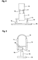
- FIG. 4 schematically shows a plan view of a support frame.
- the support frame has a front plate 10 and a rear plate 11.
- the signs are rigid surfaces made of plastic that are hardly flexible and are preferably adapted to the shape of a human body.
- the signs 10, 11 are made in a compression molding process. As a result, a stable shape is achieved, which is not completely or completely rigid, but follows to some extent the body rotation.
- attachment points can be produced precisely without fraying.
- the shield 10 is connected to the shield 11 via two spring steels 12. By bending the spring steels around shoulders, the front shield 10 is supported at the front and the rear shield 11 is at the rear adjacent the spine.
- the rear shield 11 points in the in 4 and FIG. 5 illustrated embodiment laterally webs 13 which can be folded so that the two Webs 13 are in the worn state of the support frame to the left and right of the body above the waist of a person.
- rods 14 are fixed, which open into tubes 15 movable.
- the tubes 15 are attached laterally to the body below the waist.
- each rod 14 is moved in the associated tube 15 up and down.
- the tube is provided with a coil and the rod at a corresponding end with a permanent magnet, an electric current is induced in the coil.
- two controllable fans 17 are driven, which can be mounted in particular on the front plate near the entrance 3 or at the shoulders based on the worn state or pushed into designated pockets.
- the fans are connected via hoses to the then adjacent inlet areas of channels 1. By means of the fans 17 in particular air is blown into the channels 1 and thus also into the secondary channels 5.
- Fig. 5 represents the basic structure of the support frame laterally when the spring steel 12th have been bent around shoulders and the webs 13 were folded towards the body.
- detachable straps 18 may be provided which may interconnect the front and rear panels 10, 11 at the bottom. It is advantageous to use 18 elastic compounds instead of the straps. As a result, the device can be better adjusted to different body dimensions, z. B. when using additional garments.
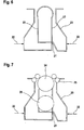
- FIG. 6 shows a plan view of a particularly suitable spring element for providing a quick release to connect the spring steels preferably in front and thus within reach with a rigid portion of the support frame.
- the spring element shown for example, consists of a single corresponding bent wire 20, which overlaps at the position 21 without being connected to each other here. If the spring element shown is compressed according to the arrows 22, then the distance between the legs 23 increases. This distance increase is used to the spring element on a button 24 or to release the spring element of this button.
- buttons 24 and 25 for example, by means of a spring steel and, for example, by means of a button 26 with a front rigid region of the support frame
- this stiff region can be achieved by compressing the spring element, as in FIG FIG. 6 indicated by the arrows 22 - very quickly released from the spring steels and discarded.
- the rear rigid area is also dropped.
- FIG. 8 shows a section of a particularly suitable embodiment of the support frame in a side view when it is worn by a person correctly attached.
- the front shield 10 may be implemented analogously or in the manner already described above and connected to the illustrated rear shield 11.
- FIG. 8 illustrated support frame differs from the support frame according to the FIGS. 4 and 5 among other things, that instead of lateral webs 13, a lateral support 27 is provided, which binds the shield 11 to the hip belt 16.
- the connection to the hip belt 16 can be done directly or - as described below - on (at least) another fastener.
- the rod / tube combination 14, 15, which in the manner already described for Power generation is configured is connected at one end via a ball head or a ball joint 28 with the shield 11 and at the other end also via a ball head or a ball joint 28 with the lateral support 27.
- the rod / tube combination may also be connected to the lateral support 27 and / or the rear shield 11 via a conventional hinge (eg, a hinge).
- the lateral support 27 has a displaceable connecting member 29, on which the tube 15 engages via the ball joint 28 described.
- the displaceability of the connecting member 29 refers to the fact that this is axially displaceable relative to the lateral support 27, so that the support frame can be adjusted to different sized people.
- the lateral support 27 is substantially tubular or rod-shaped.
- the connecting member 29 comprises the lateral support 27 on the outside.
- the lateral support 27 is, as also out FIG. 8 results in at one end via a ball or a ball joint 28 connected to the rear plate 11. At the other end, the lateral support is attached via a further ball head or a further ball joint 28 to the waist belt 16 or a fastening means connected to the hip belt 16.
- the plate 11 has vertically offset several attachment points for the ball joint 28 of the rod 14, so that here is a proper adjustment or adaptation of the support frame to the size of the person who is to receive the support frame is possible (not shown).
- the advantage of in FIG. 8 In the embodiment shown, this embodiment restricts the user less in his movement than a (likewise possible) embodiment with fixed hinges, due to the fact that ball-bearing-mounted elements are used. Nevertheless, the relative movement between hip and spine can be used for the necessary power generation.
- FIG. 8 shows, the rod / tube combination 14, 15, a spring element 30 for damping.
- FIG. 8 embodiment shown thus has a damper and a fixed lifting rod, the ends of which are each mounted in ball heads 28.
- the adaptation to different body sizes with simultaneous damping is thus guaranteed.
- a hip belt 16 is used, which is constructed in such a way that the rigid part of the damper unit, ie the lateral support 27, can be moved via a ball head 28 is fastened. So that the acting forces are better distributed and not "fold away" the elements involved by the pressure, a fastening member 31 is provided for receiving the ball heads (on both sides of the user, ie right and left).
- the attachment member 31 is preferably connected to the hip belt 16 and has a ball head 28 for receiving the lateral support 27.
- the fastening means 31 can preferably be produced in the form of a plate, in particular of ballistic packages.
- the base material can be used, that also for the ballistic formation of the shields 10, 11 is used.
- FIG. 8 a possible elastic connection 32 is shown, which is suitable to eliminate the straps 18.
- the elastic connection 32 has in the in FIG. 8 illustrated embodiment in a simple manner on a hook and loop fastener.
- each power generation device operates a fan 17 (or other electronic unit).
- FIGS. 1 to 8 can be combined with each other.
Landscapes
- Engineering & Computer Science (AREA)
- General Engineering & Computer Science (AREA)
- Professional, Industrial, Or Sporting Protective Garments (AREA)
- Portable Outdoor Equipment (AREA)
- Rehabilitation Tools (AREA)
- Automatic Cycles, And Cycles In General (AREA)
- Press Drives And Press Lines (AREA)
- Soil Working Implements (AREA)
- Outer Garments And Coats (AREA)
- Massaging Devices (AREA)
Priority Applications (1)
| Application Number | Priority Date | Filing Date | Title |
|---|---|---|---|
| EP08009546A EP2016843B1 (fr) | 2007-05-25 | 2008-05-26 | Pièce de vêtement dotée d'un dispositif d'aération pour un corps humain |
Applications Claiming Priority (2)
| Application Number | Priority Date | Filing Date | Title |
|---|---|---|---|
| EP07108898.3A EP1994840B1 (fr) | 2007-05-25 | 2007-05-25 | Vêtement avec un dispositif d'aération |
| EP08009546A EP2016843B1 (fr) | 2007-05-25 | 2008-05-26 | Pièce de vêtement dotée d'un dispositif d'aération pour un corps humain |
Publications (2)
| Publication Number | Publication Date |
|---|---|
| EP2016843A1 true EP2016843A1 (fr) | 2009-01-21 |
| EP2016843B1 EP2016843B1 (fr) | 2011-01-05 |
Family
ID=38617233
Family Applications (4)
| Application Number | Title | Priority Date | Filing Date |
|---|---|---|---|
| EP07108898.3A Not-in-force EP1994840B1 (fr) | 2007-05-25 | 2007-05-25 | Vêtement avec un dispositif d'aération |
| EP08009557A Not-in-force EP1994841B1 (fr) | 2007-05-25 | 2008-05-26 | Structure de support |
| EP08009546A Not-in-force EP2016843B1 (fr) | 2007-05-25 | 2008-05-26 | Pièce de vêtement dotée d'un dispositif d'aération pour un corps humain |
| EP08020733A Withdrawn EP2052632A1 (fr) | 2007-05-25 | 2008-05-26 | Structure de support |
Family Applications Before (2)
| Application Number | Title | Priority Date | Filing Date |
|---|---|---|---|
| EP07108898.3A Not-in-force EP1994840B1 (fr) | 2007-05-25 | 2007-05-25 | Vêtement avec un dispositif d'aération |
| EP08009557A Not-in-force EP1994841B1 (fr) | 2007-05-25 | 2008-05-26 | Structure de support |
Family Applications After (1)
| Application Number | Title | Priority Date | Filing Date |
|---|---|---|---|
| EP08020733A Withdrawn EP2052632A1 (fr) | 2007-05-25 | 2008-05-26 | Structure de support |
Country Status (5)
| Country | Link |
|---|---|
| EP (4) | EP1994840B1 (fr) |
| AT (2) | ATE493901T1 (fr) |
| DE (2) | DE502008000093D1 (fr) |
| DK (1) | DK1994840T3 (fr) |
| ES (3) | ES2672312T3 (fr) |
Cited By (5)
| Publication number | Priority date | Publication date | Assignee | Title |
|---|---|---|---|---|
| DE102009042455A1 (de) | 2009-09-23 | 2011-03-31 | Hexonia Gmbh | Tragsystem mit einer ballistischen Schutzweste |
| DE102010029041A1 (de) | 2010-05-17 | 2011-11-17 | Hexonia Gmbh | Trägersystem |
| DE102010029037A1 (de) | 2010-05-17 | 2011-11-17 | Hexonia Gmbh | Ballistische Schutzweste |
| DE102010029042A1 (de) | 2010-05-17 | 2011-11-17 | Hexonia Gmbh | Trägersystem und Hüftgurt |
| DE102010029035A1 (de) | 2010-05-17 | 2011-11-17 | Hexonia Gmbh | Trägersystem mit einem Front- und Rückenteil und Mitteln zur Befestigung an einem menschlichen Oberkörper |
Families Citing this family (2)
| Publication number | Priority date | Publication date | Assignee | Title |
|---|---|---|---|---|
| US10690450B2 (en) | 2015-09-25 | 2020-06-23 | Med-Eng, Llc | Bomb disposal suit with back protector |
| DE102017118647A1 (de) * | 2017-08-16 | 2019-02-21 | Felix Lohrke | Bekleidungsstück mit kühlender Eigenschaft |
Citations (5)
| Publication number | Priority date | Publication date | Assignee | Title |
|---|---|---|---|---|
| EP1142515A1 (fr) | 1999-08-26 | 2001-10-10 | Seft Development Laboratory Co. Ltd. | Literie, coussin, matelas, chaise, vetements et chaussures refroidis |
| US20030028948A1 (en) * | 2001-06-25 | 2003-02-13 | Chambers Paul A. | Personal cooling or warming system using closed loop fluid flow |
| WO2004065862A2 (fr) * | 2003-01-14 | 2004-08-05 | Harvie Mark R | Systeme personnel de refroidissement et de chauffage |
| EP1464242A1 (fr) * | 2003-04-01 | 2004-10-06 | Clemson University | Vêtement pour la régulation du milieu microclimatique et structure composite |
| EP1552759A1 (fr) * | 2002-07-10 | 2005-07-13 | Seft Development Laboratory Co. Ltd. | Vetements maintenant le corps au frais |
Family Cites Families (6)
| Publication number | Priority date | Publication date | Assignee | Title |
|---|---|---|---|---|
| JP2002218769A (ja) * | 2001-01-19 | 2002-08-02 | Seiko Epson Corp | 圧電発電装置を備えた衣類または衣類用発電装置 |
| US6685071B2 (en) * | 2002-01-16 | 2004-02-03 | Jeffrey Prather | Convertible bag for transporting articles and for ballistic protection |
| US6982497B2 (en) * | 2003-03-17 | 2006-01-03 | Lightning Packs, Llc | Backpack for harvesting electrical energy during walking and for minimizing shoulder strain |
| US6842908B1 (en) * | 2003-07-02 | 2005-01-18 | Yugen Gaisha Kuroiwa Kogyo | Stab proof vest |
| US7124593B2 (en) * | 2003-09-02 | 2006-10-24 | Steve Feher | Temperature conditioning apparatus for the trunk of a human body |
| WO2007047810A2 (fr) * | 2005-10-20 | 2007-04-26 | Tiax Llc | Systeme et procede d'aeration du corps |
-
2007
- 2007-05-25 ES ES07108898.3T patent/ES2672312T3/es active Active
- 2007-05-25 EP EP07108898.3A patent/EP1994840B1/fr not_active Not-in-force
- 2007-05-25 DK DK07108898.3T patent/DK1994840T3/en active
-
2008
- 2008-05-26 EP EP08009557A patent/EP1994841B1/fr not_active Not-in-force
- 2008-05-26 AT AT08009546T patent/ATE493901T1/de active
- 2008-05-26 ES ES08009546T patent/ES2359277T3/es active Active
- 2008-05-26 DE DE502008000093T patent/DE502008000093D1/de active Active
- 2008-05-26 EP EP08009546A patent/EP2016843B1/fr not_active Not-in-force
- 2008-05-26 EP EP08020733A patent/EP2052632A1/fr not_active Withdrawn
- 2008-05-26 DE DE502008002188T patent/DE502008002188D1/de active Active
- 2008-05-26 ES ES08009557T patent/ES2332614T3/es active Active
- 2008-05-26 AT AT08009557T patent/ATE441336T1/de active
Patent Citations (5)
| Publication number | Priority date | Publication date | Assignee | Title |
|---|---|---|---|---|
| EP1142515A1 (fr) | 1999-08-26 | 2001-10-10 | Seft Development Laboratory Co. Ltd. | Literie, coussin, matelas, chaise, vetements et chaussures refroidis |
| US20030028948A1 (en) * | 2001-06-25 | 2003-02-13 | Chambers Paul A. | Personal cooling or warming system using closed loop fluid flow |
| EP1552759A1 (fr) * | 2002-07-10 | 2005-07-13 | Seft Development Laboratory Co. Ltd. | Vetements maintenant le corps au frais |
| WO2004065862A2 (fr) * | 2003-01-14 | 2004-08-05 | Harvie Mark R | Systeme personnel de refroidissement et de chauffage |
| EP1464242A1 (fr) * | 2003-04-01 | 2004-10-06 | Clemson University | Vêtement pour la régulation du milieu microclimatique et structure composite |
Cited By (12)
| Publication number | Priority date | Publication date | Assignee | Title |
|---|---|---|---|---|
| DE102009042455A1 (de) | 2009-09-23 | 2011-03-31 | Hexonia Gmbh | Tragsystem mit einer ballistischen Schutzweste |
| WO2011036107A2 (fr) | 2009-09-23 | 2011-03-31 | Hexonia Gmbh | Système de portage muni d'un gilet pare-balles |
| US9200871B2 (en) | 2009-09-23 | 2015-12-01 | Hexonia Gmbh | Carrying system comprising a ballistic body armor |
| DE102009042455B4 (de) * | 2009-09-23 | 2016-03-17 | Hexonia Gmbh | Tragsystem mit einer ballistischen Schutzweste |
| DE102010029041A1 (de) | 2010-05-17 | 2011-11-17 | Hexonia Gmbh | Trägersystem |
| DE102010029037A1 (de) | 2010-05-17 | 2011-11-17 | Hexonia Gmbh | Ballistische Schutzweste |
| DE102010029042A1 (de) | 2010-05-17 | 2011-11-17 | Hexonia Gmbh | Trägersystem und Hüftgurt |
| DE102010029035A1 (de) | 2010-05-17 | 2011-11-17 | Hexonia Gmbh | Trägersystem mit einem Front- und Rückenteil und Mitteln zur Befestigung an einem menschlichen Oberkörper |
| EP2387909A2 (fr) | 2010-05-17 | 2011-11-23 | Hexonia GmbH | Système de support doté d'un élément frontal et arrière et moyens de fixation sur le buste d'un corps humain |
| EP2387910A2 (fr) | 2010-05-17 | 2011-11-23 | Hexonia GmbH | Système de support |
| DE202010017814U1 (de) | 2010-05-17 | 2012-09-20 | Hexonia Gmbh | Trägersystem und Hüftgurt |
| DE102010029035B4 (de) * | 2010-05-17 | 2019-10-31 | Hexonia Gmbh | Trägersystem mit einem Front- und Rückenteil und Mitteln zur Befestigung an einem menschlichen Oberkörper |
Also Published As
| Publication number | Publication date |
|---|---|
| ES2359277T3 (es) | 2011-05-20 |
| ATE441336T1 (de) | 2009-09-15 |
| EP2052632A1 (fr) | 2009-04-29 |
| DK1994840T3 (en) | 2018-06-18 |
| EP1994841B1 (fr) | 2009-09-02 |
| EP2016843B1 (fr) | 2011-01-05 |
| EP1994840B1 (fr) | 2018-03-07 |
| EP1994841A1 (fr) | 2008-11-26 |
| DE502008002188D1 (de) | 2011-02-17 |
| DE502008000093D1 (de) | 2009-10-15 |
| ES2672312T3 (es) | 2018-06-13 |
| ATE493901T1 (de) | 2011-01-15 |
| EP1994840A1 (fr) | 2008-11-26 |
| ES2332614T3 (es) | 2010-02-09 |
Similar Documents
| Publication | Publication Date | Title |
|---|---|---|
| EP2016843B1 (fr) | Pièce de vêtement dotée d'un dispositif d'aération pour un corps humain | |
| WO2008074440A2 (fr) | Vêtement pour climatisation personnelle | |
| CH620348A5 (fr) | ||
| EP2473074B1 (fr) | Vêtement avec ouvertures d'aération | |
| DE3237713A1 (de) | Unterkleid | |
| DE10017852A1 (de) | Verbessertes kühlendes Kleidungsstück für Personen | |
| DE112024000068T5 (de) | Stilldecke mit integriertem kühlventilator | |
| DE102007048106B4 (de) | Schutzweste | |
| EP1555489A2 (fr) | Vêtement pour un dispositif de climatisation individuelle | |
| WO2007143980A1 (fr) | Article d'habillement | |
| EP2560591B1 (fr) | Dispositif de refroidissement | |
| DE69808081T2 (de) | Kugel- und stichschutzjacke | |
| DE202006001380U1 (de) | Kombinationsbekleidung zur Klimaregulierung | |
| CH703908A2 (de) | Umrüstsatz für ein oberbekleidungsstück sowie ein erweiterungsfähiges oberbekleidungsstück. | |
| EP1163485A1 (fr) | Matiere de camouflage universelle pour tenue de camouflage et utilisee a des fins de camouflage | |
| WO2019034196A1 (fr) | Vêtement doté de propriétés rafraîchissantes | |
| EP2088879B1 (fr) | Dispositif de ventilation actif portatif | |
| EP0171671A2 (fr) | Dispositif pour la prévention d'infections | |
| DE202020102367U1 (de) | Belüftungsmatte | |
| DE202006009317U1 (de) | Bekleidungsstück | |
| DE19922141C2 (de) | Röntgenschutzmantel | |
| DE202009000852U1 (de) | Atmungsaktive Gamasche oder Textilie mit auf einer Trägerschicht verteilt angeordneten Strukturelementen aus wärmereflektierendem/-absorpierendem Material | |
| EP0843975A1 (fr) | Dispositif pour empêcher un rayonnement de chaleur d'être visible à l'extérieur | |
| EP3562344B1 (fr) | Sous-vêtement | |
| DE202025000885U1 (de) | Pferdedecke mit Polster |
Legal Events
| Date | Code | Title | Description |
|---|---|---|---|
| PUAI | Public reference made under article 153(3) epc to a published international application that has entered the european phase |
Free format text: ORIGINAL CODE: 0009012 |
|
| AK | Designated contracting states |
Kind code of ref document: A1 Designated state(s): AT BE BG CH CY CZ DE DK EE ES FI FR GB GR HR HU IE IS IT LI LT LU LV MC MT NL NO PL PT RO SE SI SK TR |
|
| AX | Request for extension of the european patent |
Extension state: AL BA MK RS |
|
| 17P | Request for examination filed |
Effective date: 20090320 |
|
| 17Q | First examination report despatched |
Effective date: 20090427 |
|
| AKX | Designation fees paid |
Designated state(s): AT BE BG CH CY CZ DE DK EE ES FI FR GB GR HR HU IE IS IT LI LT LU LV MC MT NL NO PL PT RO SE SI SK TR |
|
| GRAP | Despatch of communication of intention to grant a patent |
Free format text: ORIGINAL CODE: EPIDOSNIGR1 |
|
| GRAS | Grant fee paid |
Free format text: ORIGINAL CODE: EPIDOSNIGR3 |
|
| GRAA | (expected) grant |
Free format text: ORIGINAL CODE: 0009210 |
|
| AK | Designated contracting states |
Kind code of ref document: B1 Designated state(s): AT BE BG CH CY CZ DE DK EE ES FI FR GB GR HR HU IE IS IT LI LT LU LV MC MT NL NO PL PT RO SE SI SK TR |
|
| REG | Reference to a national code |
Ref country code: GB Ref legal event code: FG4D Free format text: NOT ENGLISH |
|
| REG | Reference to a national code |
Ref country code: CH Ref legal event code: EP |
|
| REG | Reference to a national code |
Ref country code: IE Ref legal event code: FG4D Free format text: LANGUAGE OF EP DOCUMENT: GERMAN |
|
| REF | Corresponds to: |
Ref document number: 502008002188 Country of ref document: DE Date of ref document: 20110217 Kind code of ref document: P |
|
| REG | Reference to a national code |
Ref country code: DE Ref legal event code: R096 Ref document number: 502008002188 Country of ref document: DE Effective date: 20110217 |
|
| REG | Reference to a national code |
Ref country code: SE Ref legal event code: TRGR |
|
| REG | Reference to a national code |
Ref country code: NL Ref legal event code: T3 |
|
| REG | Reference to a national code |
Ref country code: NO Ref legal event code: T2 Effective date: 20110105 |
|
| REG | Reference to a national code |
Ref country code: ES Ref legal event code: FG2A Ref document number: 2359277 Country of ref document: ES Kind code of ref document: T3 Effective date: 20110520 |
|
| PG25 | Lapsed in a contracting state [announced via postgrant information from national office to epo] |
Ref country code: SI Free format text: LAPSE BECAUSE OF FAILURE TO SUBMIT A TRANSLATION OF THE DESCRIPTION OR TO PAY THE FEE WITHIN THE PRESCRIBED TIME-LIMIT Effective date: 20110105 |
|
| LTIE | Lt: invalidation of european patent or patent extension |
Effective date: 20110105 |
|
| PG25 | Lapsed in a contracting state [announced via postgrant information from national office to epo] |
Ref country code: HR Free format text: LAPSE BECAUSE OF FAILURE TO SUBMIT A TRANSLATION OF THE DESCRIPTION OR TO PAY THE FEE WITHIN THE PRESCRIBED TIME-LIMIT Effective date: 20110105 Ref country code: PT Free format text: LAPSE BECAUSE OF FAILURE TO SUBMIT A TRANSLATION OF THE DESCRIPTION OR TO PAY THE FEE WITHIN THE PRESCRIBED TIME-LIMIT Effective date: 20110505 Ref country code: LT Free format text: LAPSE BECAUSE OF FAILURE TO SUBMIT A TRANSLATION OF THE DESCRIPTION OR TO PAY THE FEE WITHIN THE PRESCRIBED TIME-LIMIT Effective date: 20110105 Ref country code: GR Free format text: LAPSE BECAUSE OF FAILURE TO SUBMIT A TRANSLATION OF THE DESCRIPTION OR TO PAY THE FEE WITHIN THE PRESCRIBED TIME-LIMIT Effective date: 20110406 Ref country code: IS Free format text: LAPSE BECAUSE OF FAILURE TO SUBMIT A TRANSLATION OF THE DESCRIPTION OR TO PAY THE FEE WITHIN THE PRESCRIBED TIME-LIMIT Effective date: 20110505 Ref country code: LV Free format text: LAPSE BECAUSE OF FAILURE TO SUBMIT A TRANSLATION OF THE DESCRIPTION OR TO PAY THE FEE WITHIN THE PRESCRIBED TIME-LIMIT Effective date: 20110105 |
|
| PGFP | Annual fee paid to national office [announced via postgrant information from national office to epo] |
Ref country code: ES Payment date: 20110520 Year of fee payment: 4 Ref country code: SE Payment date: 20110513 Year of fee payment: 4 Ref country code: TR Payment date: 20110520 Year of fee payment: 4 |
|
| REG | Reference to a national code |
Ref country code: IE Ref legal event code: FD4D |
|
| PG25 | Lapsed in a contracting state [announced via postgrant information from national office to epo] |
Ref country code: PL Free format text: LAPSE BECAUSE OF FAILURE TO SUBMIT A TRANSLATION OF THE DESCRIPTION OR TO PAY THE FEE WITHIN THE PRESCRIBED TIME-LIMIT Effective date: 20110105 Ref country code: BG Free format text: LAPSE BECAUSE OF FAILURE TO SUBMIT A TRANSLATION OF THE DESCRIPTION OR TO PAY THE FEE WITHIN THE PRESCRIBED TIME-LIMIT Effective date: 20110405 Ref country code: CY Free format text: LAPSE BECAUSE OF FAILURE TO SUBMIT A TRANSLATION OF THE DESCRIPTION OR TO PAY THE FEE WITHIN THE PRESCRIBED TIME-LIMIT Effective date: 20110105 Ref country code: FI Free format text: LAPSE BECAUSE OF FAILURE TO SUBMIT A TRANSLATION OF THE DESCRIPTION OR TO PAY THE FEE WITHIN THE PRESCRIBED TIME-LIMIT Effective date: 20110105 |
|
| PGFP | Annual fee paid to national office [announced via postgrant information from national office to epo] |
Ref country code: NL Payment date: 20110601 Year of fee payment: 4 |
|
| PG25 | Lapsed in a contracting state [announced via postgrant information from national office to epo] |
Ref country code: EE Free format text: LAPSE BECAUSE OF FAILURE TO SUBMIT A TRANSLATION OF THE DESCRIPTION OR TO PAY THE FEE WITHIN THE PRESCRIBED TIME-LIMIT Effective date: 20110105 Ref country code: IE Free format text: LAPSE BECAUSE OF FAILURE TO SUBMIT A TRANSLATION OF THE DESCRIPTION OR TO PAY THE FEE WITHIN THE PRESCRIBED TIME-LIMIT Effective date: 20110105 Ref country code: DK Free format text: LAPSE BECAUSE OF FAILURE TO SUBMIT A TRANSLATION OF THE DESCRIPTION OR TO PAY THE FEE WITHIN THE PRESCRIBED TIME-LIMIT Effective date: 20110105 |
|
| PLBE | No opposition filed within time limit |
Free format text: ORIGINAL CODE: 0009261 |
|
| STAA | Information on the status of an ep patent application or granted ep patent |
Free format text: STATUS: NO OPPOSITION FILED WITHIN TIME LIMIT |
|
| BERE | Be: lapsed |
Owner name: HEXONIA G.M.B.H. Effective date: 20110531 |
|
| PG25 | Lapsed in a contracting state [announced via postgrant information from national office to epo] |
Ref country code: RO Free format text: LAPSE BECAUSE OF FAILURE TO SUBMIT A TRANSLATION OF THE DESCRIPTION OR TO PAY THE FEE WITHIN THE PRESCRIBED TIME-LIMIT Effective date: 20110105 Ref country code: CZ Free format text: LAPSE BECAUSE OF FAILURE TO SUBMIT A TRANSLATION OF THE DESCRIPTION OR TO PAY THE FEE WITHIN THE PRESCRIBED TIME-LIMIT Effective date: 20110105 Ref country code: SK Free format text: LAPSE BECAUSE OF FAILURE TO SUBMIT A TRANSLATION OF THE DESCRIPTION OR TO PAY THE FEE WITHIN THE PRESCRIBED TIME-LIMIT Effective date: 20110105 |
|
| 26N | No opposition filed |
Effective date: 20111006 |
|
| PG25 | Lapsed in a contracting state [announced via postgrant information from national office to epo] |
Ref country code: MT Free format text: LAPSE BECAUSE OF FAILURE TO SUBMIT A TRANSLATION OF THE DESCRIPTION OR TO PAY THE FEE WITHIN THE PRESCRIBED TIME-LIMIT Effective date: 20110105 Ref country code: MC Free format text: LAPSE BECAUSE OF NON-PAYMENT OF DUE FEES Effective date: 20110531 |
|
| PGFP | Annual fee paid to national office [announced via postgrant information from national office to epo] |
Ref country code: IT Payment date: 20110531 Year of fee payment: 4 |
|
| REG | Reference to a national code |
Ref country code: DE Ref legal event code: R097 Ref document number: 502008002188 Country of ref document: DE Effective date: 20111006 |
|
| REG | Reference to a national code |
Ref country code: FR Ref legal event code: ST Effective date: 20120131 |
|
| PG25 | Lapsed in a contracting state [announced via postgrant information from national office to epo] |
Ref country code: BE Free format text: LAPSE BECAUSE OF NON-PAYMENT OF DUE FEES Effective date: 20110531 |
|
| PG25 | Lapsed in a contracting state [announced via postgrant information from national office to epo] |
Ref country code: FR Free format text: LAPSE BECAUSE OF NON-PAYMENT OF DUE FEES Effective date: 20110531 |
|
| PGFP | Annual fee paid to national office [announced via postgrant information from national office to epo] |
Ref country code: NO Payment date: 20120509 Year of fee payment: 5 |
|
| REG | Reference to a national code |
Ref country code: NL Ref legal event code: V1 Effective date: 20121201 |
|
| REG | Reference to a national code |
Ref country code: CH Ref legal event code: PL |
|
| REG | Reference to a national code |
Ref country code: SE Ref legal event code: EUG |
|
| GBPC | Gb: european patent ceased through non-payment of renewal fee |
Effective date: 20120526 |
|
| PG25 | Lapsed in a contracting state [announced via postgrant information from national office to epo] |
Ref country code: CH Free format text: LAPSE BECAUSE OF NON-PAYMENT OF DUE FEES Effective date: 20120531 Ref country code: LI Free format text: LAPSE BECAUSE OF NON-PAYMENT OF DUE FEES Effective date: 20120531 |
|
| PG25 | Lapsed in a contracting state [announced via postgrant information from national office to epo] |
Ref country code: SE Free format text: LAPSE BECAUSE OF NON-PAYMENT OF DUE FEES Effective date: 20120527 Ref country code: IT Free format text: LAPSE BECAUSE OF NON-PAYMENT OF DUE FEES Effective date: 20120526 |
|
| PG25 | Lapsed in a contracting state [announced via postgrant information from national office to epo] |
Ref country code: NL Free format text: LAPSE BECAUSE OF NON-PAYMENT OF DUE FEES Effective date: 20121201 |
|
| PG25 | Lapsed in a contracting state [announced via postgrant information from national office to epo] |
Ref country code: GB Free format text: LAPSE BECAUSE OF NON-PAYMENT OF DUE FEES Effective date: 20120526 |
|
| PG25 | Lapsed in a contracting state [announced via postgrant information from national office to epo] |
Ref country code: LU Free format text: LAPSE BECAUSE OF NON-PAYMENT OF DUE FEES Effective date: 20110526 |
|
| REG | Reference to a national code |
Ref country code: ES Ref legal event code: FD2A Effective date: 20130820 |
|
| PG25 | Lapsed in a contracting state [announced via postgrant information from national office to epo] |
Ref country code: HU Free format text: LAPSE BECAUSE OF FAILURE TO SUBMIT A TRANSLATION OF THE DESCRIPTION OR TO PAY THE FEE WITHIN THE PRESCRIBED TIME-LIMIT Effective date: 20110105 Ref country code: ES Free format text: LAPSE BECAUSE OF NON-PAYMENT OF DUE FEES Effective date: 20120527 |
|
| PG25 | Lapsed in a contracting state [announced via postgrant information from national office to epo] |
Ref country code: NO Free format text: LAPSE BECAUSE OF NON-PAYMENT OF DUE FEES Effective date: 20130531 |
|
| PG25 | Lapsed in a contracting state [announced via postgrant information from national office to epo] |
Ref country code: TR Free format text: LAPSE BECAUSE OF NON-PAYMENT OF DUE FEES Effective date: 20120526 |
|
| REG | Reference to a national code |
Ref country code: AT Ref legal event code: MM01 Ref document number: 493901 Country of ref document: AT Kind code of ref document: T Effective date: 20130526 |
|
| PG25 | Lapsed in a contracting state [announced via postgrant information from national office to epo] |
Ref country code: AT Free format text: LAPSE BECAUSE OF NON-PAYMENT OF DUE FEES Effective date: 20130526 |
|
| PGFP | Annual fee paid to national office [announced via postgrant information from national office to epo] |
Ref country code: DE Payment date: 20170531 Year of fee payment: 10 |
|
| REG | Reference to a national code |
Ref country code: DE Ref legal event code: R119 Ref document number: 502008002188 Country of ref document: DE |
|
| PG25 | Lapsed in a contracting state [announced via postgrant information from national office to epo] |
Ref country code: DE Free format text: LAPSE BECAUSE OF NON-PAYMENT OF DUE FEES Effective date: 20181201 |