EP2016893A2 - Procédé et kit de maintenance d'un environnement stérile durant l'étalonnage d'un dispositif médical - Google Patents
Procédé et kit de maintenance d'un environnement stérile durant l'étalonnage d'un dispositif médical Download PDFInfo
- Publication number
- EP2016893A2 EP2016893A2 EP08252079A EP08252079A EP2016893A2 EP 2016893 A2 EP2016893 A2 EP 2016893A2 EP 08252079 A EP08252079 A EP 08252079A EP 08252079 A EP08252079 A EP 08252079A EP 2016893 A2 EP2016893 A2 EP 2016893A2
- Authority
- EP
- European Patent Office
- Prior art keywords
- temperature
- medical device
- kit
- temperature indicator
- sensor
- Prior art date
- Legal status (The legal status is an assumption and is not a legal conclusion. Google has not performed a legal analysis and makes no representation as to the accuracy of the status listed.)
- Granted
Links
Images


Classifications
-
- A—HUMAN NECESSITIES
- A61—MEDICAL OR VETERINARY SCIENCE; HYGIENE
- A61B—DIAGNOSIS; SURGERY; IDENTIFICATION
- A61B5/00—Measuring for diagnostic purposes; Identification of persons
- A61B5/03—Measuring fluid pressure within the body other than blood pressure, e.g. cerebral pressure ; Measuring pressure in body tissues or organs
- A61B5/031—Intracranial pressure
-
- A—HUMAN NECESSITIES
- A61—MEDICAL OR VETERINARY SCIENCE; HYGIENE
- A61B—DIAGNOSIS; SURGERY; IDENTIFICATION
- A61B5/00—Measuring for diagnostic purposes; Identification of persons
- A61B5/145—Measuring characteristics of blood in vivo, e.g. gas concentration or pH-value ; Measuring characteristics of body fluids or tissues, e.g. interstitial fluid or cerebral tissue
- A61B5/1495—Calibrating or testing of in-vivo probes
-
- G—PHYSICS
- G01—MEASURING; TESTING
- G01K—MEASURING TEMPERATURE; MEASURING QUANTITY OF HEAT; THERMALLY-SENSITIVE ELEMENTS NOT OTHERWISE PROVIDED FOR
- G01K13/00—Thermometers specially adapted for specific purposes
-
- G—PHYSICS
- G01—MEASURING; TESTING
- G01L—MEASURING FORCE, STRESS, TORQUE, WORK, MECHANICAL POWER, MECHANICAL EFFICIENCY, OR FLUID PRESSURE
- G01L27/00—Testing or calibrating of apparatus for measuring fluid pressure
- G01L27/002—Calibrating, i.e. establishing true relation between transducer output value and value to be measured, zeroing, linearising or span error determination
-
- A—HUMAN NECESSITIES
- A61—MEDICAL OR VETERINARY SCIENCE; HYGIENE
- A61B—DIAGNOSIS; SURGERY; IDENTIFICATION
- A61B2562/00—Details of sensors; Constructional details of sensor housings or probes; Accessories for sensors
- A61B2562/24—Hygienic packaging for medical sensors; Maintaining apparatus for sensor hygiene
- A61B2562/242—Packaging, i.e. for packaging the sensor or apparatus before use
Definitions
- the present invention relates to a method and kit capable of maintaining a sterile environment during calibration of a medical device, in particular during a temperature-specific calibration of an implantable sensor.
- Medical procedures typically require the use of sterile medical devices. Some such devices need to be calibrated at a specific temperature prior to use. However, bringing the device to the desired temperature and/or calibrating the device can contaminate the device, thereby potentially adding complications to the procedure by requiring further sterilization steps before use.
- Various medical sensors typically face such difficulties. Prior to use, these sensors must be calibrated and/or zeroed at a desired temperature (e.g., body temperature).
- a desired temperature e.g., body temperature
- One common method for performing the calibration includes warming sterile water or saline to a desired temperature in order to mimic body conditions while maintaining a sterile environment.
- the sterile sensor can be removed from a packaging and placed into the sterile water or saline.
- a non-sterile calibration device can be brought into communication with the sensor in order to perform the desired calibration.
- Such a procedure is deficient in many regards. First, the presence of the non-sterile calibration device risks contamination of the sensor. Next, due to such risk, the procedure can limit the proximity of the calibration device to the sterile sensor thereby potentially resulting in an inaccurate calibration. As such, the above-described calibration procedure is inefficient and error-prone.
- the device is best calibrated at an exact temperature immediately prior to use.
- certain implantable intra-cranial pressure sensors need to be zeroed exactly at body temperature immediately prior to implantation.
- Such invasive procedures require accurate calibration steps while maintaining sterility in order to enhance patient safety and increase the success rate of the procedure.
- the presently disclosed embodiments provide methods and kits for maintaining a medical device in a sterile atmosphere during a calibration and/or zeroing procedure. More specifically, the presently disclosed embodiments allow for a user to accurately bring the medical device to an extremely specific desired temperature (e.g., body temperature) and perform a required calibration and/or zeroing step without removing the device from the sterile environment. As will be shown, the presently disclosed embodiments allow for the device to remain within the container during the calibration step and therefore right up to the point of use (e.g., implantation). Therefore, the presently disclosed method and kit allow for increased precision and safety in performing medical procedures. Various aspects of the invention are summarized below.
- the invention provides a method for calibrating a medical device at an extremely specific temperature while maintaining the sterility of the device.
- the method can include packaging a temperature indicator adjacent to a medical device within a sterile container so that the indicator can accurately determine and indicate the current temperature of the medical device.
- the temperature indicator can be positioned within the sterile container so as to remain visible to a user (i.e., through a clear portion of the container).
- the temperature indicator can include an adhesive layer capable of securing the indicator at the desired position within the sterile container.
- the method can include applying and/or removing heat to the container so as to bring the medical device to the desired temperature.
- the temperature indicator can indicate a temperature change and, more specifically, indicate to the user (for example, via a visible color change) when the medical device has stabilized at the desired temperature.
- the temperature indicator can utilize microencapsulated liquid crystal technology thereby allowing for a visible color change indicative of a temperature change in the range of about 0.5°C to about 2.0°C.
- the method can further include removing the sterile medical device from the container, and performing a desired procedure with the medical device (e.g., implanting the medical device in a patient).
- the medical device can be any type of device which should be maintained in a sterile environment prior to use and, more specifically, maintained in a sterile condition during a calibration step performed at a desired temperature.
- the device can be a sensor such as an implantable pressure sensor, a temperature sensor, an oxygen sensor, a pH sensor, etc. More specifically, the device can be an implantable pressure sensor capable of measuring an intra-ventricular pressure wherein the sensor is calibrated at body temperature immediately prior to use (i.e., implantation on or within a patient's skull).
- a kit which can include a sterile container (e.g., a blister packaging) housing a medical device and a temperature indicator.
- the container can maintain the medical device and temperature indicator in a sterile condition.
- the temperature indicator can be positioned adjacent to the medical device so as to be capable of accurately indicating the current temperature of the medical device.
- the temperature indicator can be positioned relative to the container so as to be visible to a user through a clear portion of the sterile container.
- the temperature indicator can be capable of indicating when the temperature indicator is at the desired temperature thereby providing an accurate indication of when the medical device is at the desired temperature and therefore ready for calibration.
- the kit can include instructions on how to use (e.g., steps to follow when calibrating the particular medical device).
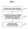
- FIG. 1 is a diagrammatic overview of an exemplary embodiment of the presently disclosed method
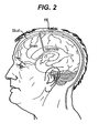
- FIG. 2 is a representation of an implantable pressure sensor in communication with a patient's brain
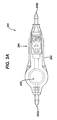
- FIG. 3A is a top view of an implantable device having a pressure sensor capable of being utilized with an embodiment of the presently disclosed method and/or kit;
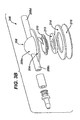
- FIG. 3B is an exploded view of the implantable device of FIG. 3A ;
- FIG. 4 is a front view of an exemplary embodiment of a blister package capable of maintaining a medical device in a sterile environment
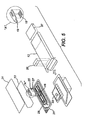
- FIG 5 is an exploded view of the container of FIG. 4 showing various components capable of being housed within the container;
- FIG. 6 is an exemplary embodiment of the presently disclosed temperature indicator.
- the presently disclosed embodiments provide a method and kit capable of maintaining a medical device in a sterile environment during a calibration step. More specifically, the method can accurately determine the temperature of the medical device while the medical device remains disposed in a sterile container so as to allow for the device to be calibrated at a desired temperature (e.g., body temperature) while the device remains in the container.
- the temperature of the device can be accurately determined by a temperature indicator also disposed within the sterile container, and positioned adjacent to (e.g., above, near or underneath) the device so as to be capable of accurately determining the temperature of the medical device.
- the temperature indicator can be positioned relative to the container such that the indicator is visible to a user through a clear portion of the container.
- FIG. 1 provides a general overview of an exemplary embodiment of steps included in the presently disclosed method.
- the method can generally be represented by three steps. Initially, the method can include packaging a medical device and temperature indicator within a sterile container (Step 50). Next, heat can be applied (or removed, if necessary) in order to place the contents of the container (i.e., the medical device and the temperature indicator) at the desired calibration temperature (such as body temperature, "B.T.") (Step 100). Once at the desired temperature, the device can be calibrated and/or zeroed while the device remains in a sterile environment (Step 150). Steps 50, 100, and 150 will now be discussed in detail.
- the initial step (Step 50) includes packaging a medical device and a temperature indicator within a sterile container.
- the medical device contains a temperature-sensitive sensor.
- a temperature-sensitive sensor typically, such medical devices are required to be calibrated at a specific temperature immediately prior to use.
- the sterility of such devices must be maintained up to and during such calibration steps.
- These sensors can include pressure sensors, temperature sensors, pH sensors, oxygen sensors, or any other type of sensors.
- the device can be one of the embodiments of implantable shunt devices having pressure sensors as disclosed in assignee's co-pending U.S. Patent Applicant No. 10/907,665, filed on April 11, 2005 , entitled "Pressure Sensing Devices," the entirety of which is incorporated herein by reference.
- a device 16 can be placed in communication with a patient's ventricle so as to measure an intra-ventricular pressure. Due to the invasive nature of such devices, maintaining the sterility of the device 16 up to the point of implantation is important. Furthermore, in order to accurately utilize the device 16, the implantable pressure device 16, and in particular its pressure sensor, needs to be zeroed at body temperature immediately prior to implantation.
- FIGS. 3A and 3B provide an exemplary embodiment of such an implantable device capable of being utilized with the presently disclosed kit or method.
- a pressure sensor assembly 206 is shown that can be disposed within a valve housing of an implantable shunt or valve 200 that can be used to control fluid flow.
- the exemplary valve 200 can be used alone or in combination with a pressure sensor assembly that is disposed in the distal portion of a ventricular catheter, and/or other pressure sensor assemblies disposed upstream or downstream of the valve 200.
- FIG.3A illustrates an implantable valve 200 having valve housing 202 with an inlet 202a and an outlet 202b.
- the valve housing 202 can contain a valve mechanism 204 for controlling the flow of fluid from the inlet 202a to the outlet 202b, and a pressure sensor assembly 206 for measuring a pressure of the fluid flowing through the valve 200, as will be described in more detail with respect to FIG. 3B .
- valve 200 can have a variety of other configurations and the valve mechanism 204, pressure sensor assembly 206, inlet 202a, and outlet 202b can be positioned at various locations relative to one another.
- the inlet 202a can extend at a right angle with respect to the pressure sensor assembly 206 such that the inlet 202a extends in a direction substantially transverse to a longitudinal axis of the valve 200.
- the valve mechanism 204 can also have a variety of configurations. By way of non-limiting example, exemplary valves are described in U.S.
- An exemplary pressure sensor assembly 206 is shown in more detail in FIG. 3B , can include a housing or reservoir 208, a sensor 212, and a backing 216.
- the illustrated pressure sensor assembly 206 also includes a needle guard 210 and a washer 214, as will be discussed in more detail below.
- the sensor housing 208 can have a variety of shapes and sizes, but in the illustrated exemplary embodiment the sensor housing 208 has a generally hemi-spherical or domed portion 208a that defines a pumping reservoir therein.
- the sensor housing 208 can also include an inlet tube 208c that couples to the inlet 202a of the valve 200, and an outlet tube 208d that couples to the outlet 202b of the valve 200.
- the reservoir chamber defined by the housing 202 is sealed, thereby allowing fluid to flow from the inlet 202a of the valve 200, through the sensor housing 208, through the valve mechanism 204, and out the outlet 202b in the valve 200.
- the sensor housing 208 can also include a flange 208b formed around a base of the domed portion 208a to allow the device to be secured to tissue.
- the flange 208b can include one or more suture holes formed therein for receiving suture to attach the flange 208b to tissue.
- the sensor housing 206 can include a sensor 212 disposed therein.
- the sensor 212 can be formed on a microchip which can be coupled to an antenna for communicating a sensed pressure to an external device.
- the antenna can have a substantially circular shape, and the microchip sensor can be coupled to the antenna.
- the antenna can take various forms such as, for example, a gold microcoil.
- the sensor 212 can also include a fluid-impermeable coating disposed there around, as previously described, to protect the sensor from fluid flowing through the sensor housing 208.
- the size will vary depending on the valve 200, but in one exemplary embodiment the microchip sensor 212 has a size that is in the range of about 1 mm to 3 mm, and more preferably that is about 2.5 mm 2 .
- exemplary embodiments of a pressure sensor and antenna are described in more detail in U.S. Pat. No. 5,321,989 , U.S. Pat. No. 5,431,057 , and EP Patent No. 1 312 302 .
- the senor 212 which is disposed within the sensor housing 208, is adapted to measure the pressure of fluid flowing through the sensor housing 208.
- the inlet 202a of the valve 200 can be coupled to a ventricular catheter for receiving fluid flow from the ventricles, and the outlet 202b can be coupled to a drainage catheter.
- the pressure of the fluid will apply a force to active sensor membranes formed on the sensor 212, thereby allowing the fluid pressure to be measured.
- the sensed pressure can be communicated, via the antenna, to an external reading device.
- the sensor assembly 206 can also include a washer 214.
- the washer 214 can be provided to seat the sensor 212, such that the washer 214 and sensor 212 are positioned against the backing 216.
- the washer 214 can also be configured such that the sensor 212 is sub-flush with the washer 214. Such a configuration may protect the sensor 212 from potential damage when the domed portion 208a of the housing 208 is depressed to pump fluid through the housing 208, or to otherwise test the valve or clear the valve from debris, etc.
- the sensor assembly 206 can also include a needle guard 210 for protecting the sensor 212.
- the needle guard 210 can protect the sensor 212 from coming into contact with the domed portion 208a of the housing 208 when the domed portion 208a is depressed, as the needle guard 210 can be positioned between the sensor 212 and the domed portion 208a.
- the needle guard 210 can also be provided to protect the sensor from a needle being inserted through the domed portion 208a of the sensor housing 208, thereby preventing potential damage to the sensor 212.
- a needle may be used to deliver or withdraw fluid from the sensor housing 208.
- the shape of the needle guard 210 can vary depending on the shape of the sensor assembly 206, in an exemplary embodiment, as shown, the needle guard 210 has a substantially planar, circular shape and it is adapted to be disposed between the domed portion 208a of the housing 208 and the sensor 212.
- the needle guard 210 can, however, include an opening formed therein and positioned adjacent to the microchip sensor 212 to allow fluid flowing through the sensor housing 208 to come into contact with the sensor 212.
- a flange or protective member is disposed over the opening, without blocking the opening from fluid flow, to prevent a user from accidentally inserted a needle through the opening.
- a person skilled in the art will appreciate that a variety of other techniques can be used to protect the sensor 212.
- the presently disclosed method further includes, as shown diagrammatically in FIG. 4 , packaging a temperature indicator 18 within the container 12 so that the indicator 18 and medical device 16 are maintained in a sterile atmosphere. Additionally, the temperature indicator 18 can be positioned relative to the medical device 16 such that the reading of the temperature indicator 18 can provide an accurate reading as to the temperature of the medical device 16. As such, the temperature indicator 18 can be placed above, adjacent to, near, beneath, etc. of the medical device such that the temperature indicator 18 provides an accurate reading as to the temperature of the medical device 16. Where it is a sensor on the medical device 16 that will be calibrated at temperature, the temperature indicator 18 should be placed so as to provide an accurate reading of the temperature of that part of the device 16.
- the components can be packaged such that the temperature indicator 18 is visible to a user prior to removing the medical device 16 from the sterile environment.
- packaging allows for a user to visualize a color change of the indicator 18 which indicates a temperature change and ultimately indicates when the temperature of the indicator 18, and thereby the medical device 16, has stabilized at the desired temperature (i.e., the calibration temperature).
- a length 14a and a width 14b of the container 14 includes a transparent material (e.g. a polymer or mixture of polymers) such that a user can visualize the temperature indicator 18 while the indicator 18 remains in the sterile environment.
- the medical device 16 (as indicated by dashed lines) can be positioned beneath the temperature indicator 18 such that the indicator 18 can accurately determine and indicate the temperature of the medical device.
- the container 14 can include a blister packaging.
- the sterile container 14 can be disposed within an outer container 12 (shown in FIG. 5 ) capable of preventing damage to the device 16 during shipping and/or storing of the kit 10.
- various configurations of containers 12, 14 are within the spirit and scope of the present invention.
- various components can be included within the outer container 12 so as to maximize the sterility of the medical device 16, as well as maximize the accuracy of the temperature indicator 18.
- the medical device 16 can be positioned so as to be housed in a multi-layered 21, 23, 29, 31 blister packaging.
- the temperature indicator 18 can be adhered (e.g., via an adhesive) to one side of a foam (or similar type material) retainer 19 such that the retainer 19 can be positioned immediately above the device 16 thereby allowing the indicator 18 to accurately determine the temperature of the medical device 16.
- various identification elements e.g., radiopaque tube 27 and/or sensor identification 25
- various other components can also be included within the outer container 12.
- various patient/user information, instructions for use, etc. can be included in the container 12.
- a CD/DVD 33 having such instructions can be included in the container 12.
- appropriate labeling 37 can be applied to the container 12.
- various components can be added or removed from the embodiment described above while remaining within the spirit and scope of the present invention.
- the indicator 18 can be any device capable of accurately determining and providing a visible indication of a temperature change.
- the temperature indicator 18 can provide a color change or a numerical change in response to a temperature change.
- the temperature indicator 18 can detect and indicate (e.g., by color change) a change in temperature in the range of about 0.5°C to about 2.0°C. In an exemplary embodiment, the temperature indicator 18 can detect and indicate a change in temperature of about 0.5°C.
- FIG. 6 provides an exemplary embodiment of a temperature indicator 18 capable of being utilized in the presently disclosed method.
- the temperature indicator 18 can include a number of segments 20, 22, 24 wherein each segment is capable of responding (i.e., illuminating) to a particular temperature.
- the segments 20, 22, 24 are capable of responding to three distinct temperatures respectively wherein temperature 1 is different from temperature 2 by about 0.5°C to about 1.5°C, and temperature 2 is different from temperature 3 by about 0.5°C to about 1.5°C.
- the first segment 20 turns a color (e.g., green) to indicate a temperature of about 37°C while the remaining segments 22, 24 remain black; next, the second segment 22 turns the color (can be green or a different color) to indicate a temperature of about 38°C while the remaining segments 20, 24 remain (or return to) black. Finally, the third segment 24 can be adapted to turn color (green or another color) to indicate a temperature of about 39°C while the remaining segments 20, 22 remain (or return to) black.
- the temperature indicator 18 can differentiate between 37°C, 38°C, and 39°C and thereby allow for the medical device 16 to be accurately calibrated and/or zeroed at the desired temperature (for example, 37°C as opposed to 38°C).
- the temperature indicator 18 can include any number and any shape of segments and remain within the spirit and scope of the present invention. Further, as will be appreciated, these segments can be adapted to indicate any range of temperatures (for example, 20°C, 21°C, 22°C as opposed to 37°C, 38°C, 39°C). In an exemplary embodiment, the temperature indicator 18 is a microencapsulated liquid crystal temperature indicator available from American Thermal Instruments, Inc. of Beavercreek, Ohio.
- liquid crystal is one of the names given to a state of matter intermediate between that of the conventional crystalline solid and isotropic liquid. Other names include mesophase and mesomorphic state. Liquid crystals possess the mechanical properties of liquids (i.e., flow) and the optical properties of solids (i.e., they are anisotropic). Liquid crystals also possess some unique properties of their own which form the basis for their practical applications.
- liquid crystals Many different types exist.
- One particularly useful class of liquid crystals has been known historically as cholesteric liquid crystals. These materials have the ability to selectively reflect light and the color of the reflected light can be made to change as the temperature changes.
- the normal color change sequence is from red to green to blue (through the visible spectrum) with increasing temperature within their color reflective temperature range. Because of their unique temperature-sensitive properties, the materials are also called thermochromic liquid crystals (TLC's).
- TLC's thermochromic liquid crystals
- the rate of change from one reflected color to another as well as the specific temperatures at which certain color changes occur can also be accurately controlled.
- a common method of producing such devices is to produce a coating (ink) containing preferably a microencapsulated Thermochomic Liquid Crystal (TLC) mixture and use a printing method to apply it to the supporting substrate. A black ink is then applied on top of the dry TLC coating and color change effects are viewed from the reverse (uncoated) side of the sheet.
- Liquid crystal thermometers/temperature indicators are usually comprised of a series of liquid crystal 'events', which change color in a sequence as the temperature changes. Behind or adjacent to each number (temperature) on the TLC thermometers is an 'active' area coated with a precisely calibrated TLC mixture designed to change color at the temperature in question.
- the medical device 16 and temperature indicator 18 can be packaged within the container 12 by a manufacturer following generally accepted packaging procedures designed to optimize and ensure a sterile condition within the container 12. Any such packaging process is clearly within the spirit and scope of the present invention.
- the method includes applying a heat (or removing heat, if necessary) in order to bring the temperature indicator 18, and therefore the medical device 16, to a desired temperature.
- the temperature indicator 18 can be positioned relative to the medical device 16 such that the temperature of the temperature indicator 18 is indicative of the temperature of the medical device 16.
- heat is applied and/or withdrawn (as necessary) to the sterile inner container 14 until the temperature indicator 18 (as seen through the clear container 14) indicates that the temperature has stabilized at the calibration temperature.
- the calibration temperature is body temperature.
- any device and/or method capable of applying and/or withdrawing heat to the container 14 may be utilized by the presently disclosed method. More specifically, any heating unit capable of delivering an amount of heat to the container 14 such that the contents of the container 14 (i.e., the medical device 16 and temperature indicator 18) can be maintained at a constant temperature for a desired duration is within the spirit and scope of the present invention.
- the device 16 can be calibrated and/or zeroed for use (Step 150).
- Various medical procedures require the medical device 16 to be calibrated and/or zeroed at a desired temperature prior to use in order to obtain an accurate and reliable reading.
- the device 16 is calibrated while the temperature indicator 18 indicates that the temperature of the medical device 16 is at body temperature (such as in the case of the implantable pressure sensors discussed above).
- the method can further include removing the sterile medical device 16 from the sterile container 14, and utilizing the medical device 16 in the desired procedure.
- kits 10 are also provided wherein the kit 10 includes a container 12 capable of housing a medical device 16 and temperature indicator 18 in a sterile condition.
- the kit 10 can include instructions on how to calibrate and/or zero the medical device 16 at a certain temperature with the aid of the temperature indicator 18.
- the kit 10 allows for the medical device 16 to be calibrated at a desired temperature while maintaining a sterile environment at all times.
- the device can be packaged with the foam insert 19 pressing the temperature indicator 18 up against the device, and in particular, in the vicinity of pressure sensor 212.
- the identifier 25 packaged with the device can indicate a unique pressure sensor 212 for which calibration coefficients and/or data is available from the time of manufacture.
- the package can be heated until the temperature indicator indicates that the device has reached body temperature, and a hand held programmer/communication device (not shown) can be used to read a signal from the device that is indicative of pressure.
- this reading will represent a "zeroing" of this individual sensor for purposes of comparing later signals from the device that will be used after implantation to calculate the absolute intracranial pressure of the patient's cerebrospinal fluid.
Landscapes
- Health & Medical Sciences (AREA)
- Life Sciences & Earth Sciences (AREA)
- Physics & Mathematics (AREA)
- Medical Informatics (AREA)
- Surgery (AREA)
- Biophysics (AREA)
- Pathology (AREA)
- Engineering & Computer Science (AREA)
- Biomedical Technology (AREA)
- Heart & Thoracic Surgery (AREA)
- General Physics & Mathematics (AREA)
- Molecular Biology (AREA)
- Veterinary Medicine (AREA)
- Animal Behavior & Ethology (AREA)
- General Health & Medical Sciences (AREA)
- Public Health (AREA)
- Hematology (AREA)
- Neurosurgery (AREA)
- Optics & Photonics (AREA)
- Measuring And Recording Apparatus For Diagnosis (AREA)
- Measurement Of The Respiration, Hearing Ability, Form, And Blood Characteristics Of Living Organisms (AREA)
- Measuring Temperature Or Quantity Of Heat (AREA)
Applications Claiming Priority (1)
| Application Number | Priority Date | Filing Date | Title |
|---|---|---|---|
| US11/764,293 US7827845B2 (en) | 2007-06-18 | 2007-06-18 | Method and kit for maintaining a sterile environment during calibration of a medical device |
Publications (3)
| Publication Number | Publication Date |
|---|---|
| EP2016893A2 true EP2016893A2 (fr) | 2009-01-21 |
| EP2016893A3 EP2016893A3 (fr) | 2010-08-04 |
| EP2016893B1 EP2016893B1 (fr) | 2012-05-30 |
Family
ID=39791225
Family Applications (1)
| Application Number | Title | Priority Date | Filing Date |
|---|---|---|---|
| EP08252079A Active EP2016893B1 (fr) | 2007-06-18 | 2008-06-17 | Procédé et kit de maintenance d'un environnement stérile durant l'étalonnage d'un dispositif médical |
Country Status (5)
| Country | Link |
|---|---|
| US (1) | US7827845B2 (fr) |
| EP (1) | EP2016893B1 (fr) |
| JP (1) | JP5236361B2 (fr) |
| AU (1) | AU2008202655B2 (fr) |
| CA (1) | CA2635185C (fr) |
Families Citing this family (6)
| Publication number | Priority date | Publication date | Assignee | Title |
|---|---|---|---|---|
| US7827845B2 (en) * | 2007-06-18 | 2010-11-09 | Codman & Shurtleff, Inc. | Method and kit for maintaining a sterile environment during calibration of a medical device |
| US20090188811A1 (en) | 2007-11-28 | 2009-07-30 | Edwards Lifesciences Corporation | Preparation and maintenance of sensors |
| CN113230425B (zh) | 2013-03-13 | 2023-07-14 | 史赛克公司 | 能够提供容器中的被灭菌手术器械是否被正确灭菌的提示的灭菌容器 |
| AU2015229592B2 (en) | 2014-03-11 | 2019-03-14 | Stryker Corporation | Sterilization container with battery powered sensor module for monitoring the environment in the container |
| CA2998327A1 (fr) | 2015-09-11 | 2017-03-16 | Stryker Corporation | Enceinte de sterilisation pour instruments chirurgicaux |
| CN106175743B (zh) * | 2016-07-12 | 2019-02-22 | 苏州景昱医疗器械有限公司 | 颅内状态监护系统及监护方法 |
Citations (12)
| Publication number | Priority date | Publication date | Assignee | Title |
|---|---|---|---|---|
| US3886948A (en) | 1972-08-14 | 1975-06-03 | Hakim Co Ltd | Ventricular shunt having a variable pressure valve |
| US4332255A (en) | 1979-01-10 | 1982-06-01 | Hakim Company Limited | Shunt valve |
| US4387715A (en) | 1980-09-23 | 1983-06-14 | Hakim Company Limited | Shunt valve |
| US4551128A (en) | 1983-05-11 | 1985-11-05 | Salomon Hakim | Cerebrospinal fluid shunt valve |
| US4595390A (en) | 1983-07-21 | 1986-06-17 | Salomon Hakim | Magnetically-adjustable cerebrospinal fluid shunt valve |
| US4615691A (en) | 1983-12-08 | 1986-10-07 | Salomon Hakim | Surgically-implantable stepping motor |
| US4772257A (en) | 1983-12-08 | 1988-09-20 | Salomon Hakim | External programmer for magnetically-adjustable cerebrospinal fluid shunt valve |
| US5321989A (en) | 1990-02-12 | 1994-06-21 | Fraunhofer-Gesellschaft Zur Forderung Der Angewandten Forschung E.V. | Integratable capacitative pressure sensor and process for its manufacture |
| US5431057A (en) | 1990-02-12 | 1995-07-11 | Fraunhofer-Gesellschaft Zur Forderung Der Angewandten Forschung E.V. | Integratable capacitative pressure sensor |
| US5928182A (en) | 1997-07-02 | 1999-07-27 | Johnson & Johnson Professional, Inc. | Pediatric programmable hydrocephalus valve |
| EP1312302A2 (fr) | 2001-11-16 | 2003-05-21 | Cranium Telemetrics GmbH | Dispositif pour mesurer la pression intracranienne à l'intérieur du corps |
| US20060211946A1 (en) | 2005-03-15 | 2006-09-21 | Codman & Shurtleff, Inc. | Pressure sensing valve |
Family Cites Families (17)
| Publication number | Priority date | Publication date | Assignee | Title |
|---|---|---|---|---|
| US4475555A (en) * | 1978-10-10 | 1984-10-09 | Linder Gerald S | Universal measuring attachment for esophageal stethoscopes |
| US4331156A (en) * | 1980-03-28 | 1982-05-25 | University Patents, Inc. | Esophageal cardiac pulse monitoring apparatus and method |
| US4568330A (en) * | 1983-06-02 | 1986-02-04 | Minnesota Mining And Manufacturing Company | Cardioplegia delivery system with improved bubble trap |
| US4737020A (en) * | 1985-04-15 | 1988-04-12 | Robert Parker | Method for making battery tester for two sizes of batteries |
| US4838664A (en) * | 1986-07-10 | 1989-06-13 | Brent Graham | Diagnostic overlay |
| US4863016A (en) * | 1988-07-25 | 1989-09-05 | Abbott Laboratories | Packaging for a sterilizable calibratable medical device |
| US4941308A (en) * | 1988-07-25 | 1990-07-17 | Abbott Laboratories | Method of packaging for a sterilizable calibratable medical device |
| US4945919A (en) * | 1989-02-10 | 1990-08-07 | Yamaguchi Yakuhin Shokai Ltd. | Rhinological diagnostic device |
| GB2247951B (en) | 1990-09-17 | 1994-11-09 | Cowell Ltd W S | Indicating devices in combination with plants |
| US5329804A (en) * | 1992-10-16 | 1994-07-19 | Abbott Laboratories | Calibration system and method for calibrating a blood gas sensor |
| US5486659A (en) * | 1994-03-08 | 1996-01-23 | Rosenbush; Stuart W. | Stethoscope protection device and method for using same |
| US6467953B1 (en) * | 1999-03-30 | 2002-10-22 | Medical Solutions, Inc. | Method and apparatus for monitoring temperature of intravenously delivered fluids and other medical items |
| US6360888B1 (en) * | 1999-02-25 | 2002-03-26 | Minimed Inc. | Glucose sensor package system |
| US6582653B1 (en) * | 1999-09-27 | 2003-06-24 | Saint-Gobain Performance Plastics Corporation | Apparatus and method for the sterilization-in-place of intravenous bags and the like |
| US6560471B1 (en) * | 2001-01-02 | 2003-05-06 | Therasense, Inc. | Analyte monitoring device and methods of use |
| GB0612834D0 (en) * | 2006-06-28 | 2006-08-09 | Glysure Ltd | Sensor calibration |
| US7827845B2 (en) * | 2007-06-18 | 2010-11-09 | Codman & Shurtleff, Inc. | Method and kit for maintaining a sterile environment during calibration of a medical device |
-
2007
- 2007-06-18 US US11/764,293 patent/US7827845B2/en active Active
-
2008
- 2008-06-16 AU AU2008202655A patent/AU2008202655B2/en not_active Ceased
- 2008-06-17 CA CA2635185A patent/CA2635185C/fr active Active
- 2008-06-17 JP JP2008157387A patent/JP5236361B2/ja not_active Expired - Fee Related
- 2008-06-17 EP EP08252079A patent/EP2016893B1/fr active Active
Patent Citations (12)
| Publication number | Priority date | Publication date | Assignee | Title |
|---|---|---|---|---|
| US3886948A (en) | 1972-08-14 | 1975-06-03 | Hakim Co Ltd | Ventricular shunt having a variable pressure valve |
| US4332255A (en) | 1979-01-10 | 1982-06-01 | Hakim Company Limited | Shunt valve |
| US4387715A (en) | 1980-09-23 | 1983-06-14 | Hakim Company Limited | Shunt valve |
| US4551128A (en) | 1983-05-11 | 1985-11-05 | Salomon Hakim | Cerebrospinal fluid shunt valve |
| US4595390A (en) | 1983-07-21 | 1986-06-17 | Salomon Hakim | Magnetically-adjustable cerebrospinal fluid shunt valve |
| US4615691A (en) | 1983-12-08 | 1986-10-07 | Salomon Hakim | Surgically-implantable stepping motor |
| US4772257A (en) | 1983-12-08 | 1988-09-20 | Salomon Hakim | External programmer for magnetically-adjustable cerebrospinal fluid shunt valve |
| US5321989A (en) | 1990-02-12 | 1994-06-21 | Fraunhofer-Gesellschaft Zur Forderung Der Angewandten Forschung E.V. | Integratable capacitative pressure sensor and process for its manufacture |
| US5431057A (en) | 1990-02-12 | 1995-07-11 | Fraunhofer-Gesellschaft Zur Forderung Der Angewandten Forschung E.V. | Integratable capacitative pressure sensor |
| US5928182A (en) | 1997-07-02 | 1999-07-27 | Johnson & Johnson Professional, Inc. | Pediatric programmable hydrocephalus valve |
| EP1312302A2 (fr) | 2001-11-16 | 2003-05-21 | Cranium Telemetrics GmbH | Dispositif pour mesurer la pression intracranienne à l'intérieur du corps |
| US20060211946A1 (en) | 2005-03-15 | 2006-09-21 | Codman & Shurtleff, Inc. | Pressure sensing valve |
Also Published As
| Publication number | Publication date |
|---|---|
| EP2016893A3 (fr) | 2010-08-04 |
| CA2635185C (fr) | 2015-12-15 |
| CA2635185A1 (fr) | 2008-12-18 |
| JP2009039512A (ja) | 2009-02-26 |
| AU2008202655B2 (en) | 2013-06-27 |
| US20080307854A1 (en) | 2008-12-18 |
| EP2016893B1 (fr) | 2012-05-30 |
| JP5236361B2 (ja) | 2013-07-17 |
| US7827845B2 (en) | 2010-11-09 |
| AU2008202655A1 (en) | 2009-01-08 |
Similar Documents
| Publication | Publication Date | Title |
|---|---|---|
| EP2016893B1 (fr) | Procédé et kit de maintenance d'un environnement stérile durant l'étalonnage d'un dispositif médical | |
| EP0888744B1 (fr) | Recalibrage à zéro d'un capteur de pression in vivo | |
| US5207227A (en) | Multiprobes with thermal diffusion flow monitor | |
| US6162182A (en) | Pressure tip cannula | |
| US4608992A (en) | External magnetic detection of physiopathological and other parameters | |
| JP5595990B2 (ja) | 感圧器具 | |
| EP1053035B1 (fr) | Dispositif de perfusion de medicament implantable comprenant un regulateur de debit | |
| US8894584B2 (en) | Real time CSF flow measurement system and method | |
| AU2008237564B2 (en) | Wireless shunts with storage | |
| US20100114063A1 (en) | Catheter injection monitoring device | |
| CA2180151A1 (fr) | Systeme et procede pour le calibrage in vivo d'un capteur | |
| JP2007167645A (ja) | 患者の血圧測定を行うための血管カテーテルと流体移送システム | |
| AU2016244004B2 (en) | Syringe volume monitoring systems with hall sensor | |
| EP0303756A2 (fr) | Cathéter de thermodilution à ballon et capteur de pression | |
| Zolfaghari et al. | MRI compatible fiber optic multi sensor platform for real time vital monitoring | |
| CN116211272B (zh) | 颅内探头及颅内检测组件 | |
| CN219699918U (zh) | 颅内探头及颅内检测组件 | |
| CA2076667A1 (fr) | Sondes multiples avec moniteur de diffusion thermique | |
| US20240389904A1 (en) | Implantable chemical sensor packages with calibration features | |
| WO2004026128A1 (fr) | Appareil et methode de controle de l'etat pathologique d'un patient | |
| JPH0316643Y2 (fr) | ||
| WO2004026127A1 (fr) | Perfectionnements apportes ou associes a des dispositifs capteurs neonatals | |
| CN110196117A (zh) | 一种双参数预校准介入式探头 | |
| CN117695024A (zh) | 带有可吸收材料的单次使用的一次性经过时间指示器 | |
| AU2014203011A1 (en) | Wireless shunts with storage |
Legal Events
| Date | Code | Title | Description |
|---|---|---|---|
| PUAI | Public reference made under article 153(3) epc to a published international application that has entered the european phase |
Free format text: ORIGINAL CODE: 0009012 |
|
| PUAI | Public reference made under article 153(3) epc to a published international application that has entered the european phase |
Free format text: ORIGINAL CODE: 0009012 |
|
| AK | Designated contracting states |
Kind code of ref document: A2 Designated state(s): AT BE BG CH CY CZ DE DK EE ES FI FR GB GR HR HU IE IS IT LI LT LU LV MC MT NL NO PL PT RO SE SI SK TR |
|
| AX | Request for extension of the european patent |
Extension state: AL BA MK RS |
|
| PUAL | Search report despatched |
Free format text: ORIGINAL CODE: 0009013 |
|
| AK | Designated contracting states |
Kind code of ref document: A3 Designated state(s): AT BE BG CH CY CZ DE DK EE ES FI FR GB GR HR HU IE IS IT LI LT LU LV MC MT NL NO PL PT RO SE SI SK TR |
|
| AX | Request for extension of the european patent |
Extension state: AL BA MK RS |
|
| RIC1 | Information provided on ipc code assigned before grant |
Ipc: A61B 5/03 20060101AFI20081015BHEP Ipc: A61B 5/1495 20060101ALI20100630BHEP Ipc: A61B 5/00 20060101ALI20100630BHEP Ipc: A61L 2/00 20060101ALI20100630BHEP Ipc: G01L 27/00 20060101ALI20100630BHEP |
|
| 17P | Request for examination filed |
Effective date: 20110204 |
|
| AKX | Designation fees paid |
Designated state(s): CH DE FR GB IT LI |
|
| RIC1 | Information provided on ipc code assigned before grant |
Ipc: A61L 2/00 20060101ALI20111005BHEP Ipc: G01L 27/00 20060101ALI20111005BHEP Ipc: A61B 5/03 20060101AFI20111005BHEP Ipc: A61B 5/1495 20060101ALI20111005BHEP Ipc: A61B 5/00 20060101ALI20111005BHEP |
|
| GRAP | Despatch of communication of intention to grant a patent |
Free format text: ORIGINAL CODE: EPIDOSNIGR1 |
|
| GRAS | Grant fee paid |
Free format text: ORIGINAL CODE: EPIDOSNIGR3 |
|
| GRAA | (expected) grant |
Free format text: ORIGINAL CODE: 0009210 |
|
| AK | Designated contracting states |
Kind code of ref document: B1 Designated state(s): CH DE FR GB IT LI |
|
| REG | Reference to a national code |
Ref country code: GB Ref legal event code: FG4D |
|
| REG | Reference to a national code |
Ref country code: CH Ref legal event code: EP |
|
| REG | Reference to a national code |
Ref country code: CH Ref legal event code: NV Representative=s name: E. BLUM & CO. AG PATENT- UND MARKENANWAELTE VSP |
|
| REG | Reference to a national code |
Ref country code: DE Ref legal event code: R096 Ref document number: 602008016004 Country of ref document: DE Effective date: 20120802 |
|
| PLBE | No opposition filed within time limit |
Free format text: ORIGINAL CODE: 0009261 |
|
| STAA | Information on the status of an ep patent application or granted ep patent |
Free format text: STATUS: NO OPPOSITION FILED WITHIN TIME LIMIT |
|
| 26N | No opposition filed |
Effective date: 20130301 |
|
| REG | Reference to a national code |
Ref country code: DE Ref legal event code: R097 Ref document number: 602008016004 Country of ref document: DE Effective date: 20130301 |
|
| REG | Reference to a national code |
Ref country code: FR Ref legal event code: PLFP Year of fee payment: 9 |
|
| REG | Reference to a national code |
Ref country code: FR Ref legal event code: PLFP Year of fee payment: 10 |
|
| REG | Reference to a national code |
Ref country code: FR Ref legal event code: PLFP Year of fee payment: 11 |
|
| REG | Reference to a national code |
Ref country code: GB Ref legal event code: 732E Free format text: REGISTERED BETWEEN 20180712 AND 20180718 |
|
| REG | Reference to a national code |
Ref country code: DE Ref legal event code: R082 Ref document number: 602008016004 Country of ref document: DE Representative=s name: MUELLER-BORE & PARTNER PATENTANWAELTE PARTG MB, DE Ref country code: DE Ref legal event code: R081 Ref document number: 602008016004 Country of ref document: DE Owner name: INTEGRA LIFE SCIENCES CORPORATION, PLAINSBORO, US Free format text: FORMER OWNER: CODMAN & SHURTLEFF, INC., RAYNHAM, MASS., US |
|
| REG | Reference to a national code |
Ref country code: CH Ref legal event code: PUE Owner name: DEPUY SPINE, LLC, US Free format text: FORMER OWNER: CODMAN AND SHURTLEFF, INC., US Ref country code: CH Ref legal event code: PUE Owner name: INTEGRA LIFESCIENCES CORPORATION, US Free format text: FORMER OWNER: DEPUY SYNTHES PRODUCTS, INC., US Ref country code: CH Ref legal event code: PUE Owner name: DEPUY SYNTHES PRODUCTS, INC., US Free format text: FORMER OWNER: DEPUY SPINE, LLC, US |
|
| REG | Reference to a national code |
Ref country code: FR Ref legal event code: PLFP Year of fee payment: 16 |
|
| P01 | Opt-out of the competence of the unified patent court (upc) registered |
Effective date: 20230522 |
|
| PGFP | Annual fee paid to national office [announced via postgrant information from national office to epo] |
Ref country code: IT Payment date: 20230510 Year of fee payment: 16 |
|
| PGFP | Annual fee paid to national office [announced via postgrant information from national office to epo] |
Ref country code: GB Payment date: 20240402 Year of fee payment: 17 |
|
| PGFP | Annual fee paid to national office [announced via postgrant information from national office to epo] |
Ref country code: DE Payment date: 20240328 Year of fee payment: 17 |
|
| PGFP | Annual fee paid to national office [announced via postgrant information from national office to epo] |
Ref country code: FR Payment date: 20240408 Year of fee payment: 17 |
|
| PGFP | Annual fee paid to national office [announced via postgrant information from national office to epo] |
Ref country code: CH Payment date: 20240701 Year of fee payment: 17 |
|
| PG25 | Lapsed in a contracting state [announced via postgrant information from national office to epo] |
Ref country code: IT Free format text: LAPSE BECAUSE OF NON-PAYMENT OF DUE FEES Effective date: 20240617 |
|
| REG | Reference to a national code |
Ref country code: DE Ref legal event code: R119 Ref document number: 602008016004 Country of ref document: DE |
|
| REG | Reference to a national code |
Ref country code: CH Ref legal event code: H13 Free format text: ST27 STATUS EVENT CODE: U-0-0-H10-H13 (AS PROVIDED BY THE NATIONAL OFFICE) Effective date: 20260127 |
|
| GBPC | Gb: european patent ceased through non-payment of renewal fee |
Effective date: 20250617 |
|
| PG25 | Lapsed in a contracting state [announced via postgrant information from national office to epo] |
Ref country code: GB Free format text: LAPSE BECAUSE OF NON-PAYMENT OF DUE FEES Effective date: 20250617 |
|
| PG25 | Lapsed in a contracting state [announced via postgrant information from national office to epo] |
Ref country code: DE Free format text: LAPSE BECAUSE OF NON-PAYMENT OF DUE FEES Effective date: 20260101 |
|
| PG25 | Lapsed in a contracting state [announced via postgrant information from national office to epo] |
Ref country code: FR Free format text: LAPSE BECAUSE OF NON-PAYMENT OF DUE FEES Effective date: 20250630 |
|
| PG25 | Lapsed in a contracting state [announced via postgrant information from national office to epo] |
Ref country code: CH Free format text: LAPSE BECAUSE OF NON-PAYMENT OF DUE FEES Effective date: 20250630 |