EP2016997A1 - Dispositif microfluidique, procédé de mélange, procédé de fabrication et utilisation du dispositif - Google Patents
Dispositif microfluidique, procédé de mélange, procédé de fabrication et utilisation du dispositif Download PDFInfo
- Publication number
- EP2016997A1 EP2016997A1 EP07013434A EP07013434A EP2016997A1 EP 2016997 A1 EP2016997 A1 EP 2016997A1 EP 07013434 A EP07013434 A EP 07013434A EP 07013434 A EP07013434 A EP 07013434A EP 2016997 A1 EP2016997 A1 EP 2016997A1
- Authority
- EP
- European Patent Office
- Prior art keywords
- chamber
- hydrophilic
- areas
- hydrophobic
- liquids
- Prior art date
- Legal status (The legal status is an assumption and is not a legal conclusion. Google has not performed a legal analysis and makes no representation as to the accuracy of the status listed.)
- Granted
Links
Images

Classifications
-
- B—PERFORMING OPERATIONS; TRANSPORTING
- B01—PHYSICAL OR CHEMICAL PROCESSES OR APPARATUS IN GENERAL
- B01F—MIXING, e.g. DISSOLVING, EMULSIFYING OR DISPERSING
- B01F33/00—Other mixers; Mixing plants; Combinations of mixers
- B01F33/30—Micromixers
- B01F33/3035—Micromixers using surface tension to mix, move or hold the fluids
- B01F33/30351—Micromixers using surface tension to mix, move or hold the fluids using hydrophilic/hydrophobic surfaces
-
- B—PERFORMING OPERATIONS; TRANSPORTING
- B01—PHYSICAL OR CHEMICAL PROCESSES OR APPARATUS IN GENERAL
- B01J—CHEMICAL OR PHYSICAL PROCESSES, e.g. CATALYSIS OR COLLOID CHEMISTRY; THEIR RELEVANT APPARATUS
- B01J19/00—Chemical, physical or physico-chemical processes in general; Their relevant apparatus
- B01J19/0093—Microreactors, e.g. miniaturised or microfabricated reactors
-
- B—PERFORMING OPERATIONS; TRANSPORTING
- B01—PHYSICAL OR CHEMICAL PROCESSES OR APPARATUS IN GENERAL
- B01F—MIXING, e.g. DISSOLVING, EMULSIFYING OR DISPERSING
- B01F33/00—Other mixers; Mixing plants; Combinations of mixers
- B01F33/30—Micromixers
- B01F33/301—Micromixers using specific means for arranging the streams to be mixed, e.g. channel geometries or dispositions
- B01F33/3017—Mixing chamber
-
- B—PERFORMING OPERATIONS; TRANSPORTING
- B01—PHYSICAL OR CHEMICAL PROCESSES OR APPARATUS IN GENERAL
- B01F—MIXING, e.g. DISSOLVING, EMULSIFYING OR DISPERSING
- B01F33/00—Other mixers; Mixing plants; Combinations of mixers
- B01F33/30—Micromixers
- B01F33/302—Micromixers the materials to be mixed flowing in the form of droplets
- B01F33/3021—Micromixers the materials to be mixed flowing in the form of droplets the components to be mixed being combined in a single independent droplet, e.g. these droplets being divided by a non-miscible fluid or consisting of independent droplets
-
- B—PERFORMING OPERATIONS; TRANSPORTING
- B01—PHYSICAL OR CHEMICAL PROCESSES OR APPARATUS IN GENERAL
- B01L—CHEMICAL OR PHYSICAL LABORATORY APPARATUS FOR GENERAL USE
- B01L3/00—Containers or dishes for laboratory use, e.g. laboratory glassware; Droppers
- B01L3/50—Containers for the purpose of retaining a material to be analysed, e.g. test tubes
- B01L3/502—Containers for the purpose of retaining a material to be analysed, e.g. test tubes with fluid transport, e.g. in multi-compartment structures
- B01L3/5027—Containers for the purpose of retaining a material to be analysed, e.g. test tubes with fluid transport, e.g. in multi-compartment structures by integrated microfluidic structures, i.e. dimensions of channels and chambers are such that surface tension forces are important, e.g. lab-on-a-chip
-
- B—PERFORMING OPERATIONS; TRANSPORTING
- B01—PHYSICAL OR CHEMICAL PROCESSES OR APPARATUS IN GENERAL
- B01J—CHEMICAL OR PHYSICAL PROCESSES, e.g. CATALYSIS OR COLLOID CHEMISTRY; THEIR RELEVANT APPARATUS
- B01J2219/00—Chemical, physical or physico-chemical processes in general; Their relevant apparatus
- B01J2219/00781—Aspects relating to microreactors
- B01J2219/00783—Laminate assemblies, i.e. the reactor comprising a stack of plates
-
- B—PERFORMING OPERATIONS; TRANSPORTING
- B01—PHYSICAL OR CHEMICAL PROCESSES OR APPARATUS IN GENERAL
- B01J—CHEMICAL OR PHYSICAL PROCESSES, e.g. CATALYSIS OR COLLOID CHEMISTRY; THEIR RELEVANT APPARATUS
- B01J2219/00—Chemical, physical or physico-chemical processes in general; Their relevant apparatus
- B01J2219/00781—Aspects relating to microreactors
- B01J2219/00819—Materials of construction
- B01J2219/00833—Plastic
-
- B—PERFORMING OPERATIONS; TRANSPORTING
- B01—PHYSICAL OR CHEMICAL PROCESSES OR APPARATUS IN GENERAL
- B01J—CHEMICAL OR PHYSICAL PROCESSES, e.g. CATALYSIS OR COLLOID CHEMISTRY; THEIR RELEVANT APPARATUS
- B01J2219/00—Chemical, physical or physico-chemical processes in general; Their relevant apparatus
- B01J2219/00781—Aspects relating to microreactors
- B01J2219/00819—Materials of construction
- B01J2219/00837—Materials of construction comprising coatings other than catalytically active coatings
-
- B—PERFORMING OPERATIONS; TRANSPORTING
- B01—PHYSICAL OR CHEMICAL PROCESSES OR APPARATUS IN GENERAL
- B01J—CHEMICAL OR PHYSICAL PROCESSES, e.g. CATALYSIS OR COLLOID CHEMISTRY; THEIR RELEVANT APPARATUS
- B01J2219/00—Chemical, physical or physico-chemical processes in general; Their relevant apparatus
- B01J2219/00781—Aspects relating to microreactors
- B01J2219/00851—Additional features
- B01J2219/00858—Aspects relating to the size of the reactor
- B01J2219/0086—Dimensions of the flow channels
-
- B—PERFORMING OPERATIONS; TRANSPORTING
- B01—PHYSICAL OR CHEMICAL PROCESSES OR APPARATUS IN GENERAL
- B01J—CHEMICAL OR PHYSICAL PROCESSES, e.g. CATALYSIS OR COLLOID CHEMISTRY; THEIR RELEVANT APPARATUS
- B01J2219/00—Chemical, physical or physico-chemical processes in general; Their relevant apparatus
- B01J2219/00781—Aspects relating to microreactors
- B01J2219/00889—Mixing
-
- B—PERFORMING OPERATIONS; TRANSPORTING
- B01—PHYSICAL OR CHEMICAL PROCESSES OR APPARATUS IN GENERAL
- B01L—CHEMICAL OR PHYSICAL LABORATORY APPARATUS FOR GENERAL USE
- B01L2300/00—Additional constructional details
- B01L2300/08—Geometry, shape and general structure
- B01L2300/0861—Configuration of multiple channels and/or chambers in a single devices
- B01L2300/0867—Multiple inlets and one sample wells, e.g. mixing, dilution
-
- B—PERFORMING OPERATIONS; TRANSPORTING
- B01—PHYSICAL OR CHEMICAL PROCESSES OR APPARATUS IN GENERAL
- B01L—CHEMICAL OR PHYSICAL LABORATORY APPARATUS FOR GENERAL USE
- B01L2300/00—Additional constructional details
- B01L2300/16—Surface properties and coatings
- B01L2300/161—Control and use of surface tension forces, e.g. hydrophobic, hydrophilic
- B01L2300/165—Specific details about hydrophobic, oleophobic surfaces
-
- B—PERFORMING OPERATIONS; TRANSPORTING
- B01—PHYSICAL OR CHEMICAL PROCESSES OR APPARATUS IN GENERAL
- B01L—CHEMICAL OR PHYSICAL LABORATORY APPARATUS FOR GENERAL USE
- B01L2400/00—Moving or stopping fluids
- B01L2400/06—Valves, specific forms thereof
- B01L2400/0694—Valves, specific forms thereof vents used to stop and induce flow, backpressure valves
-
- B—PERFORMING OPERATIONS; TRANSPORTING
- B01—PHYSICAL OR CHEMICAL PROCESSES OR APPARATUS IN GENERAL
- B01L—CHEMICAL OR PHYSICAL LABORATORY APPARATUS FOR GENERAL USE
- B01L2400/00—Moving or stopping fluids
- B01L2400/08—Regulating or influencing the flow resistance
- B01L2400/084—Passive control of flow resistance
- B01L2400/088—Passive control of flow resistance by specific surface properties
Definitions
- the present invention refers to a microfluidic device comprising chambers and a method of using such device for mixing liquids.
- microfluidic systems Since initiation and activation of a chemical or biochemical process, requires mixing between reagents, microfluidic systems have much to offer, but a useful microfabricated system should be able to provide not only effective and convenient means to drive and guide liquids in microchannels but also efficient and rapid means to mix them.
- Different methods have been proposed to enhance mixing in microfluidic systems, both active and passive. Passive methods are the most attractive since they do not require external energy, while mixing, due to the dominating laminar flow, relies entirely on diffusion or chaotic advection. These methods work by increasing the contact surface and/or decreasing the diffusion path to improve mixing, but the design and manufacture is not always simple and the use of a pump to drive liquids through the channels is in most cases still a need.
- This device turns particularly useful for in vitro diagnostics (IVD) applications, reaction kinetics studies, drug- and bio-interaction screening and sample preparation before further processing.
- the present invention relates to a microfluidic device comprising a substrate, a cover, at least one chamber formed between the substrate and the cover, said chamber comprising two opposite surfaces, one on the substrate and one on the cover respectively, each surface comprising hydrophilic and hydrophobic areas, characterized in that each hydrophilic area on each of the two opposite surfaces of said chamber can be wetted independently by at least one liquid.
- the device according to the present invention may further comprise lateral hydrophilic and hydrophobic areas or patterns, said lateral hydrophilic and hydrophobic areas leading to the at least one chamber.
- said lateral hydrophilic and hydrophobic areas or patterns are comprised in microchannels, which could be formed either in the substrate or in the cover.
- the microchannels are formed both in the substrate and in the cover.
- the microchannels are formed by means of one or more spacer layers between the substrate and the cover.
- the lateral hydrophilic areas or patterns may be only on one side, that is either on the substrate or on the cover, but may also be on both the substrate and the cover.
- the hydrophilic areas are confined within or surrounded by hydrophobic areas. The surface energy in correspondence of said areas, i.e.
- the capillary force is such that a liquid, can be guided along a lateral hydrophilic area or pattern by capillary force, enter the said chamber from one side, wet part of one surface of said chamber as a thin layer without touching the opposite surface of said chamber, thus avoiding to fill the volume inside the chamber in correspondence of the hydrophilic pattern until a second liquid, either in parallel or sequentially, comes to wet part of the opposite surface of said chamber with a similar mechanism or path and eventually touches the first liquid layer, resulting in a sudden coalescence and efficient mixing between the liquids.
- the chamber is preferably a micro-chamber wherein the volume of said micro-chamber is typically comprised between 0.01 ⁇ L and 5 ⁇ L, preferably between 0.05 ⁇ L and 2 ⁇ L and the height of the micro-chamber, i.e. the distance between the wetted surfaces is typically below about 1 mm, preferably below about 300 ⁇ m so that the average diffusion distance remains relatively small. Since achieving accurate volumes in such small ranges may be difficult, it is understood however that these ranges are approximate and are not limiting.
- the liquid follows only the hydrophilic pattern also inside the chamber, that is a hydrophobic surrounding adjacent to the hydrophilic areas assures that the liquid remains confined within the pattern without ever touching laterally physical side walls.
- the volume of the liquids being mixed is thus not defined by the volume of the chamber as such but by the volume defined by the hydrophilic areas within it.
- the volume of the chamber is defined by the volume between the hydrophilic areas on the two opposite surfaces of the chamber.
- the non wetted hydrophobic areas or surrounding inside the chamber communicates with the outside of the device, e.g. by means of other side channels , so that the system is vented from all sides, allowing air to escape with proper flow and filling, without trapping air bubbles.
- the liquids to which reference is made in the present invention are preferably chemical or biochemical solutions, or reagents, in polar solvents, preferably aqueous solutions or reagents. It is of course possible to invert the position of hydrophilic and hydrophobic areas and work with non polar liquids or organic solvents instead.
- the concept disclosed in the present invention works at best if the contact angle of the hydrophilic areas is below about 30 degrees, most preferably below about 20 degrees, and if the contact angle of the hydrophobic areas is above about 100 degrees, most preferably above about 110 degrees.
- a preferred and convenient option is plasma polymerization.
- the substrate for patterning that is the material used for the device can be any suitable polymeric material, preferably but not necessarily transparent, that can be easily and cheaply manufactured by e.g. molding, and the device can be disposable.
- a hydrophobic plasma polymerization step could be executed first homogeneously on the surface to be hydrophilically patterned in order to yield a surface, which is more hydrophobic than the polymeric material used naturally might be, followed by masking and hydrophilic patterning on top of the hydrophobic surface.
- Other conditions making possible the capillary flow and the wetting of e.g. only one of two parallel surfaces without touching the other can vary and basic theories can be found in the literature. It is for example known that the width of the path is typically larger than the height of the channel, which has to be sufficiently small in order to maximize the capillary force, hence the linear velocity, but not too small because of the flow resistance.
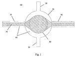
- a generic device 10 comprising a generic chamber 20, generic microfluidic channels 30 and 40 driving respectively first and second liquid to be mixed into said chamber 20, and generic side channels 50 is disclosed in figure 1 .
- hydrophilic areas (hatched) 70 and hydrophobic areas (white) 60 are distinguished from one another.
- the device 10 in figure 1 has to be seen as a transparent top view, not to scale, consisting of at least two symmetrically overlapped different layers, also defined as substrate 11 and cover 12, assembled on top of each other.
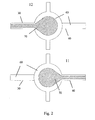
- the internal sides of substrate 11 and cover 12 are independently shown in Figures 2 and 3 , which represent two of the possible embodiments of device 10.
- figure 2 represents the embodiment in which the liquids are driven along the channels 30 and 40 by the hydrophilic area or pattern 70 present only on one surface of the channels and figure 3 represents the embodiment in which the liquids are driven along the channels 30 and 40 by the hydrophilic areas or patterns 70 present on both surfaces of the channels.
- the device 10 might contain an array of chambers 20 defined just by a hydrophilic pattern 70 on large hydrophobic surfaces 60 parallel and at short distance between them with no channels 30, 40 and 50 at all, or with channels 30, 40 and 50 differently arranged according to use. Needless to say is that different chambers in an array might also have different designs and represent different volumes.
- the first liquid comes from channel 30
- the second liquid comes from channel 40
- the reaction volume that is the volume of the liquids being mixed, is thus not defined by the volume of the chamber 20 as such but by the volume 80 defined by the hydrophilic areas within the chamber 20.
- top and bottom areas 70 inside the chamber 20 could be achieved for example by designing the top and bottom areas 70 inside the chamber 20 differently and/or by subdividing the hydrophilic areas 70 in correspondence of the mixing or reaction zone 80 by means of thin hydrophobic patterns 60 or grooves, in correspondence of which each liquid layer would stop advancing.
- the pressure inside the device is the same as outside the device, that is the system operates under atmospheric pressure. Indeed the non wetted zone in correspondence of the hydrophobic area 60 inside the chamber 20 and the side channels 50 allow air to escape. In other words, the system is vented from all sides, allowing proper flow and filling without trapping air bubbles.
- the side channels 50 might also be used to introduce in a second stage an immiscible organic liquid with the function to transport the aqueous reacted sample out of the chamber 20 as a discrete droplet or plug. This is particularly advantageous if the device 10, especially in an array format, is used for sample preparation starting from very small amounts of reagents.
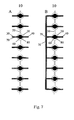
- the device 10 is however particularly suitable for a static reaction mode, where small amounts of reagents are brought into contact with each other in parallel and/or in various combinations, like for example shown in the embodiments of figure 7 , and detection is carried out in situ through the transparent body of each chamber 20.
- the device 10 can be for example advantageously used especially for in vitro diagnostics (IVD) applications, drug- and bio-interaction screening and reaction kinetics studies. The latter requires indeed a well defined start time, which can be identified with the time in which the two liquids coalesce.
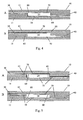
- This can be further characterized in other embodiments as shown in side view in figure 4 according to the way the hydrophilic areas 70 continue their paths and thus guide the liquid layers from the channels 30 and 40 into the chamber 20.
- the path from each channel is continuous, continuing to advance along the same plane.
- the path is discontinuous, in the sense that it follows the step due to the different depth of the chamber 20.
- FIG. 5A and 5B Analogous considerations can be made with reference to figures 5A and 5B , which in turn refer to the embodiment of figure 3 with both top and bottom surfaces of the channels 30 and 40, that is with both the substrate 11 and the cover 12, being patterned.
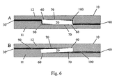
- Figures 6A and 6B provide a schematic representation of the paths followed by the liquids 90 and 100 along said hydrophilic paths from the channels 30 and 40 respectively into the chamber 20 for the embodiments of fig. 4A and 4B respectively. Analogously, similar paths for the liquids 90 and 100 can be assumed for the embodiments of fig. 5 .
Landscapes
- Chemical & Material Sciences (AREA)
- Chemical Kinetics & Catalysis (AREA)
- Health & Medical Sciences (AREA)
- Dispersion Chemistry (AREA)
- Analytical Chemistry (AREA)
- General Health & Medical Sciences (AREA)
- Hematology (AREA)
- Clinical Laboratory Science (AREA)
- Organic Chemistry (AREA)
- Automatic Analysis And Handling Materials Therefor (AREA)
- Physical Or Chemical Processes And Apparatus (AREA)
- Micromachines (AREA)
Priority Applications (5)
| Application Number | Priority Date | Filing Date | Title |
|---|---|---|---|
| DE602007011745T DE602007011745D1 (de) | 2007-07-10 | 2007-07-10 | Mikrofluidische Vorrichtung, Mischverfahren und Verwendung der Vorrichtung |
| AT07013434T ATE494061T1 (de) | 2007-07-10 | 2007-07-10 | Mikrofluidische vorrichtung, mischverfahren und verwendung der vorrichtung |
| EP07013434A EP2016997B1 (fr) | 2007-07-10 | 2007-07-10 | Dispositif microfluidique, procédé de mélange et utilisation du dispositif |
| US12/142,019 US8911683B2 (en) | 2007-07-10 | 2008-06-19 | Micro chamber |
| JP2008177266A JP5027070B2 (ja) | 2007-07-10 | 2008-07-07 | マイクロチャンバ |
Applications Claiming Priority (1)
| Application Number | Priority Date | Filing Date | Title |
|---|---|---|---|
| EP07013434A EP2016997B1 (fr) | 2007-07-10 | 2007-07-10 | Dispositif microfluidique, procédé de mélange et utilisation du dispositif |
Publications (2)
| Publication Number | Publication Date |
|---|---|
| EP2016997A1 true EP2016997A1 (fr) | 2009-01-21 |
| EP2016997B1 EP2016997B1 (fr) | 2011-01-05 |
Family
ID=38752765
Family Applications (1)
| Application Number | Title | Priority Date | Filing Date |
|---|---|---|---|
| EP07013434A Not-in-force EP2016997B1 (fr) | 2007-07-10 | 2007-07-10 | Dispositif microfluidique, procédé de mélange et utilisation du dispositif |
Country Status (5)
| Country | Link |
|---|---|
| US (1) | US8911683B2 (fr) |
| EP (1) | EP2016997B1 (fr) |
| JP (1) | JP5027070B2 (fr) |
| AT (1) | ATE494061T1 (fr) |
| DE (1) | DE602007011745D1 (fr) |
Cited By (3)
| Publication number | Priority date | Publication date | Assignee | Title |
|---|---|---|---|---|
| FR2996544A1 (fr) * | 2012-10-08 | 2014-04-11 | Ecole Polytech | Circuit microfluidique permettant la mise en contact de gouttes de plusieurs fluides, et procede microfluidique correspondant. |
| US20150225771A1 (en) * | 2012-09-19 | 2015-08-13 | Nec Corporation | Analysis chip and analysis device |
| WO2022063847A1 (fr) | 2020-09-23 | 2022-03-31 | Roche Diagnostics Gmbh | Procédé de détection d'un analyte à l'aide de nanoparticules métalliques sur une électrode |
Families Citing this family (27)
| Publication number | Priority date | Publication date | Assignee | Title |
|---|---|---|---|---|
| US20070047388A1 (en) * | 2005-08-25 | 2007-03-01 | Rockwell Scientific Licensing, Llc | Fluidic mixing structure, method for fabricating same, and mixing method |
| US8053191B2 (en) | 2006-08-31 | 2011-11-08 | Westend Asset Clearinghouse Company, Llc | Iterative nucleic acid assembly using activation of vector-encoded traits |
| EP2213364A1 (fr) * | 2009-01-30 | 2010-08-04 | Albert-Ludwigs-Universität Freiburg | Motifs de guide de phase pour la manipulation de liquides |
| US10207240B2 (en) | 2009-11-03 | 2019-02-19 | Gen9, Inc. | Methods and microfluidic devices for the manipulation of droplets in high fidelity polynucleotide assembly |
| WO2011066185A1 (fr) | 2009-11-25 | 2011-06-03 | Gen9, Inc. | Dispositifs microfluidiques et procédés pour la synthèse génique |
| WO2011085075A2 (fr) | 2010-01-07 | 2011-07-14 | Gen9, Inc. | Assemblage de polynucléotides haute fidélité |
| US8204172B1 (en) | 2010-03-17 | 2012-06-19 | General Electric Company | System and method of prior image constrained image reconstruction using short scan image data and objective function minimization |
| WO2012024696A2 (fr) * | 2010-08-20 | 2012-02-23 | Purdue Research Foundation | Traitement par laser d'un support pour la microfluidique et diverses autres applications |
| CN103502448B (zh) | 2010-11-12 | 2017-03-29 | Gen9股份有限公司 | 核酸合成的方法和设备 |
| WO2012064975A1 (fr) | 2010-11-12 | 2012-05-18 | Gen9, Inc. | Puces à protéines et leurs procédés d'utilisation et de fabrication |
| CN103597203B (zh) * | 2011-06-09 | 2016-10-12 | Pp能源有限责任公司 | 用于连接风力涡轮机的两个转子叶片段的升降装置 |
| LT2944693T (lt) | 2011-08-26 | 2019-08-26 | Gen9, Inc. | Kompozicijos ir būdai, skirti nukleorūgščių didelio tikslumo sąrankai |
| US9150853B2 (en) | 2012-03-21 | 2015-10-06 | Gen9, Inc. | Methods for screening proteins using DNA encoded chemical libraries as templates for enzyme catalysis |
| CA2871505C (fr) | 2012-04-24 | 2021-10-12 | Gen9, Inc. | Procedes de tri d'acides nucleiques et de clonage in vitro multiplex preparatoire |
| IL236303B (en) | 2012-06-25 | 2022-07-01 | Gen9 Inc | Methods for high-throughput nucleic acid assembly and sequencing |
| JP5922791B2 (ja) * | 2012-10-29 | 2016-05-24 | 京セラ株式会社 | 弾性表面波センサ |
| JP5839526B1 (ja) * | 2015-02-06 | 2016-01-06 | 秋田県 | 微小液滴を形成する反応デバイス及びこれを用いた電界撹拌方法 |
| US9604209B2 (en) | 2015-03-19 | 2017-03-28 | International Business Machines Corporation | Microfluidic device with anti-wetting, venting areas |
| KR102614682B1 (ko) * | 2017-12-11 | 2023-12-19 | 덴카 주식회사 | 액체 시료 검사 키트용 막 담체, 액체 시료 검사 키트, 액체 시료 검사 키트의 제조 방법, 액체 시료의 검사 방법 및 막 담체 |
| GB201801019D0 (en) * | 2018-01-22 | 2018-03-07 | Q Linea Ab | Sample holder |
| US20220193678A1 (en) * | 2019-04-08 | 2022-06-23 | Technion Research And Development Foundation, Ltd. | Multiplexed array of nanoliter droplet array device |
| CN114096855A (zh) * | 2019-07-08 | 2022-02-25 | 积水化学工业株式会社 | 送液方法以及检测芯片 |
| JP7561041B2 (ja) * | 2020-04-28 | 2024-10-03 | デクセリアルズ株式会社 | 検査チップ、及びその製造方法 |
| CN113804658B (zh) * | 2020-06-11 | 2023-06-06 | 京东方科技集团股份有限公司 | 微流控流道结构、检测系统及其使用方法 |
| KR102919524B1 (ko) * | 2021-11-26 | 2026-02-02 | 한국기계연구원 | 개폐형 디지털 유전자 증폭 키트 어셈블리 |
| US20240198336A1 (en) | 2022-12-19 | 2024-06-20 | Anchorline Biolabs, Inc. | Capillary partitioning microfluidics |
| CN116687084B (zh) * | 2023-04-13 | 2025-08-05 | 青岛大学 | 一种湿度可控的口罩及口罩湿度的控制方法 |
Citations (4)
| Publication number | Priority date | Publication date | Assignee | Title |
|---|---|---|---|---|
| WO1998039645A1 (fr) * | 1997-03-07 | 1998-09-11 | Beckman Coulter, Inc. | Nouveau capillaire |
| EP0977032A1 (fr) * | 1997-03-12 | 2000-02-02 | Kyoto Daiichi Kagaku Co., Ltd. | Instrument d'analyse d'echantillon liquide |
| EP1643231A1 (fr) * | 2003-07-09 | 2006-04-05 | Olympus Corporation | Dispositif et procede servant a deplacer et a traiter un liquide |
| WO2007024410A2 (fr) * | 2005-08-25 | 2007-03-01 | Teledyne Licensing, Llc | Structure de melange de fluides, procede pour la fabriquer et procede de melange |
Family Cites Families (3)
| Publication number | Priority date | Publication date | Assignee | Title |
|---|---|---|---|---|
| DE10002500A1 (de) | 2000-01-21 | 2001-07-26 | Univ Albert Ludwigs Freiburg | Kapillarkraftmischer |
| EP1358123A2 (fr) * | 2001-02-09 | 2003-11-05 | Wisconsin Alumni Research Foundation | Procede et structure permettant le guidage d'ecoulements microfluidiques |
| DE502006007372D1 (de) * | 2006-05-22 | 2010-08-19 | Micronas Gmbh | Vorrichtung zum Mischen von Mikrotröpfchen |
-
2007
- 2007-07-10 AT AT07013434T patent/ATE494061T1/de not_active IP Right Cessation
- 2007-07-10 DE DE602007011745T patent/DE602007011745D1/de active Active
- 2007-07-10 EP EP07013434A patent/EP2016997B1/fr not_active Not-in-force
-
2008
- 2008-06-19 US US12/142,019 patent/US8911683B2/en not_active Expired - Fee Related
- 2008-07-07 JP JP2008177266A patent/JP5027070B2/ja not_active Expired - Fee Related
Patent Citations (4)
| Publication number | Priority date | Publication date | Assignee | Title |
|---|---|---|---|---|
| WO1998039645A1 (fr) * | 1997-03-07 | 1998-09-11 | Beckman Coulter, Inc. | Nouveau capillaire |
| EP0977032A1 (fr) * | 1997-03-12 | 2000-02-02 | Kyoto Daiichi Kagaku Co., Ltd. | Instrument d'analyse d'echantillon liquide |
| EP1643231A1 (fr) * | 2003-07-09 | 2006-04-05 | Olympus Corporation | Dispositif et procede servant a deplacer et a traiter un liquide |
| WO2007024410A2 (fr) * | 2005-08-25 | 2007-03-01 | Teledyne Licensing, Llc | Structure de melange de fluides, procede pour la fabriquer et procede de melange |
Cited By (6)
| Publication number | Priority date | Publication date | Assignee | Title |
|---|---|---|---|---|
| US20150225771A1 (en) * | 2012-09-19 | 2015-08-13 | Nec Corporation | Analysis chip and analysis device |
| EP2899546A4 (fr) * | 2012-09-19 | 2016-04-27 | Nec Corp | Puce d'analyse, et dispositif d'analyse |
| FR2996544A1 (fr) * | 2012-10-08 | 2014-04-11 | Ecole Polytech | Circuit microfluidique permettant la mise en contact de gouttes de plusieurs fluides, et procede microfluidique correspondant. |
| WO2014056931A1 (fr) * | 2012-10-08 | 2014-04-17 | Ecole Polytechnique | Circuit microfluidique permettant la mise en contact de gouttes de plusieurs fluides, et procédé microfluidique correspondant |
| US9943843B2 (en) | 2012-10-08 | 2018-04-17 | Ecole Polytechnique | Microfluidic circuit allowing drops of several fluids to be brought into contact, and corresponding microfluidic method |
| WO2022063847A1 (fr) | 2020-09-23 | 2022-03-31 | Roche Diagnostics Gmbh | Procédé de détection d'un analyte à l'aide de nanoparticules métalliques sur une électrode |
Also Published As
| Publication number | Publication date |
|---|---|
| DE602007011745D1 (de) | 2011-02-17 |
| US20090016932A1 (en) | 2009-01-15 |
| US8911683B2 (en) | 2014-12-16 |
| JP2009025301A (ja) | 2009-02-05 |
| JP5027070B2 (ja) | 2012-09-19 |
| ATE494061T1 (de) | 2011-01-15 |
| EP2016997B1 (fr) | 2011-01-05 |
Similar Documents
| Publication | Publication Date | Title |
|---|---|---|
| EP2016997B1 (fr) | Dispositif microfluidique, procédé de mélange et utilisation du dispositif | |
| Melin et al. | A fast passive and planar liquid sample micromixer | |
| Haeberle et al. | Microfluidic platforms for lab-on-a-chip applications | |
| KR100540143B1 (ko) | 미소 유체 제어소자 및 미소 유체의 제어 방법 | |
| US6481453B1 (en) | Microfluidic branch metering systems and methods | |
| US6890093B2 (en) | Multi-stream microfludic mixers | |
| EP1463579B1 (fr) | Melangeurs microfluidiques a ouvertures | |
| Paik et al. | Electrowetting-based droplet mixers for microfluidic systems | |
| US7094379B2 (en) | Device for parallel and synchronous injection for sequential injection of different reagents | |
| US9168521B2 (en) | Microfluidic device with deformable valve | |
| AU2005201449B2 (en) | Methods and apparatus for manipulating droplets by electrowetting-based techniques | |
| EP1539350B1 (fr) | Procedes et systemes de mesure de microfluides a extremite fermee | |
| US7329545B2 (en) | Methods for sampling a liquid flow | |
| US20210370303A1 (en) | Pressure insensitive microfluidic circuit for droplet generation and uses thereof | |
| Greenwood et al. | Sample manipulation in micro total analytical systems | |
| KR101065614B1 (ko) | 랩온어칩용 마이크로 펌프 및 마이크로 펌프 제조 방법. | |
| JP2008082961A (ja) | マイクロ流路デバイス | |
| KR100826584B1 (ko) | 바이오칩 분석을 위한 유체 채널링 액츄에이터 | |
| WO2008139401A2 (fr) | Dispositif et procédé de manipulation d'un échantillon fluidique | |
| Lee et al. | An integrated microfluidic chip for the analysis of biochemical reactions by MALDI mass spectrometry | |
| US20210197199A1 (en) | Microfluidic device channel layer | |
| TW201830019A (zh) | 微流體裝置 | |
| Koltay et al. | Micro-Fluidic Platforms | |
| KR20040091205A (ko) | 다채널 유체 조작 장치 | |
| Yao et al. | Capillary Stop Valve Design with Modified PDMS |
Legal Events
| Date | Code | Title | Description |
|---|---|---|---|
| PUAI | Public reference made under article 153(3) epc to a published international application that has entered the european phase |
Free format text: ORIGINAL CODE: 0009012 |
|
| AK | Designated contracting states |
Kind code of ref document: A1 Designated state(s): AT BE BG CH CY CZ DE DK EE ES FI FR GB GR HU IE IS IT LI LT LU LV MC MT NL PL PT RO SE SI SK TR |
|
| AX | Request for extension of the european patent |
Extension state: AL BA HR MK RS |
|
| 17P | Request for examination filed |
Effective date: 20090721 |
|
| AKX | Designation fees paid |
Designated state(s): AT BE BG CH CY CZ DE DK EE ES FI FR GB GR HU IE IS IT LI LT LU LV MC MT NL PL PT RO SE SI SK TR |
|
| 17Q | First examination report despatched |
Effective date: 20090921 |
|
| RTI1 | Title (correction) |
Free format text: MICROFLUIDIC DEVICE, METHOD OF MIXING AND USE OF THE DEVICE |
|
| GRAP | Despatch of communication of intention to grant a patent |
Free format text: ORIGINAL CODE: EPIDOSNIGR1 |
|
| GRAS | Grant fee paid |
Free format text: ORIGINAL CODE: EPIDOSNIGR3 |
|
| GRAA | (expected) grant |
Free format text: ORIGINAL CODE: 0009210 |
|
| AK | Designated contracting states |
Kind code of ref document: B1 Designated state(s): AT BE BG CH CY CZ DE DK EE ES FI FR GB GR HU IE IS IT LI LT LU LV MC MT NL PL PT RO SE SI SK TR |
|
| REG | Reference to a national code |
Ref country code: GB Ref legal event code: FG4D |
|
| REG | Reference to a national code |
Ref country code: CH Ref legal event code: EP |
|
| REG | Reference to a national code |
Ref country code: IE Ref legal event code: FG4D |
|
| REF | Corresponds to: |
Ref document number: 602007011745 Country of ref document: DE Date of ref document: 20110217 Kind code of ref document: P |
|
| REG | Reference to a national code |
Ref country code: DE Ref legal event code: R096 Ref document number: 602007011745 Country of ref document: DE Effective date: 20110217 |
|
| REG | Reference to a national code |
Ref country code: NL Ref legal event code: VDEP Effective date: 20110105 |
|
| PG25 | Lapsed in a contracting state [announced via postgrant information from national office to epo] |
Ref country code: SI Free format text: LAPSE BECAUSE OF FAILURE TO SUBMIT A TRANSLATION OF THE DESCRIPTION OR TO PAY THE FEE WITHIN THE PRESCRIBED TIME-LIMIT Effective date: 20110105 |
|
| LTIE | Lt: invalidation of european patent or patent extension |
Effective date: 20110105 |
|
| PG25 | Lapsed in a contracting state [announced via postgrant information from national office to epo] |
Ref country code: PT Free format text: LAPSE BECAUSE OF FAILURE TO SUBMIT A TRANSLATION OF THE DESCRIPTION OR TO PAY THE FEE WITHIN THE PRESCRIBED TIME-LIMIT Effective date: 20110505 Ref country code: LV Free format text: LAPSE BECAUSE OF FAILURE TO SUBMIT A TRANSLATION OF THE DESCRIPTION OR TO PAY THE FEE WITHIN THE PRESCRIBED TIME-LIMIT Effective date: 20110105 Ref country code: LT Free format text: LAPSE BECAUSE OF FAILURE TO SUBMIT A TRANSLATION OF THE DESCRIPTION OR TO PAY THE FEE WITHIN THE PRESCRIBED TIME-LIMIT Effective date: 20110105 Ref country code: GR Free format text: LAPSE BECAUSE OF FAILURE TO SUBMIT A TRANSLATION OF THE DESCRIPTION OR TO PAY THE FEE WITHIN THE PRESCRIBED TIME-LIMIT Effective date: 20110406 Ref country code: IS Free format text: LAPSE BECAUSE OF FAILURE TO SUBMIT A TRANSLATION OF THE DESCRIPTION OR TO PAY THE FEE WITHIN THE PRESCRIBED TIME-LIMIT Effective date: 20110505 Ref country code: SE Free format text: LAPSE BECAUSE OF FAILURE TO SUBMIT A TRANSLATION OF THE DESCRIPTION OR TO PAY THE FEE WITHIN THE PRESCRIBED TIME-LIMIT Effective date: 20110105 Ref country code: ES Free format text: LAPSE BECAUSE OF FAILURE TO SUBMIT A TRANSLATION OF THE DESCRIPTION OR TO PAY THE FEE WITHIN THE PRESCRIBED TIME-LIMIT Effective date: 20110416 |
|
| PG25 | Lapsed in a contracting state [announced via postgrant information from national office to epo] |
Ref country code: BG Free format text: LAPSE BECAUSE OF FAILURE TO SUBMIT A TRANSLATION OF THE DESCRIPTION OR TO PAY THE FEE WITHIN THE PRESCRIBED TIME-LIMIT Effective date: 20110405 Ref country code: BE Free format text: LAPSE BECAUSE OF FAILURE TO SUBMIT A TRANSLATION OF THE DESCRIPTION OR TO PAY THE FEE WITHIN THE PRESCRIBED TIME-LIMIT Effective date: 20110105 Ref country code: PL Free format text: LAPSE BECAUSE OF FAILURE TO SUBMIT A TRANSLATION OF THE DESCRIPTION OR TO PAY THE FEE WITHIN THE PRESCRIBED TIME-LIMIT Effective date: 20110105 Ref country code: AT Free format text: LAPSE BECAUSE OF FAILURE TO SUBMIT A TRANSLATION OF THE DESCRIPTION OR TO PAY THE FEE WITHIN THE PRESCRIBED TIME-LIMIT Effective date: 20110105 Ref country code: FI Free format text: LAPSE BECAUSE OF FAILURE TO SUBMIT A TRANSLATION OF THE DESCRIPTION OR TO PAY THE FEE WITHIN THE PRESCRIBED TIME-LIMIT Effective date: 20110105 Ref country code: NL Free format text: LAPSE BECAUSE OF FAILURE TO SUBMIT A TRANSLATION OF THE DESCRIPTION OR TO PAY THE FEE WITHIN THE PRESCRIBED TIME-LIMIT Effective date: 20110105 Ref country code: CY Free format text: LAPSE BECAUSE OF FAILURE TO SUBMIT A TRANSLATION OF THE DESCRIPTION OR TO PAY THE FEE WITHIN THE PRESCRIBED TIME-LIMIT Effective date: 20110105 |
|
| PG25 | Lapsed in a contracting state [announced via postgrant information from national office to epo] |
Ref country code: EE Free format text: LAPSE BECAUSE OF FAILURE TO SUBMIT A TRANSLATION OF THE DESCRIPTION OR TO PAY THE FEE WITHIN THE PRESCRIBED TIME-LIMIT Effective date: 20110105 Ref country code: DK Free format text: LAPSE BECAUSE OF FAILURE TO SUBMIT A TRANSLATION OF THE DESCRIPTION OR TO PAY THE FEE WITHIN THE PRESCRIBED TIME-LIMIT Effective date: 20110105 |
|
| PLBE | No opposition filed within time limit |
Free format text: ORIGINAL CODE: 0009261 |
|
| STAA | Information on the status of an ep patent application or granted ep patent |
Free format text: STATUS: NO OPPOSITION FILED WITHIN TIME LIMIT |
|
| PG25 | Lapsed in a contracting state [announced via postgrant information from national office to epo] |
Ref country code: SK Free format text: LAPSE BECAUSE OF FAILURE TO SUBMIT A TRANSLATION OF THE DESCRIPTION OR TO PAY THE FEE WITHIN THE PRESCRIBED TIME-LIMIT Effective date: 20110105 Ref country code: CZ Free format text: LAPSE BECAUSE OF FAILURE TO SUBMIT A TRANSLATION OF THE DESCRIPTION OR TO PAY THE FEE WITHIN THE PRESCRIBED TIME-LIMIT Effective date: 20110105 Ref country code: RO Free format text: LAPSE BECAUSE OF FAILURE TO SUBMIT A TRANSLATION OF THE DESCRIPTION OR TO PAY THE FEE WITHIN THE PRESCRIBED TIME-LIMIT Effective date: 20110105 |
|
| 26N | No opposition filed |
Effective date: 20111006 |
|
| PG25 | Lapsed in a contracting state [announced via postgrant information from national office to epo] |
Ref country code: IT Free format text: LAPSE BECAUSE OF FAILURE TO SUBMIT A TRANSLATION OF THE DESCRIPTION OR TO PAY THE FEE WITHIN THE PRESCRIBED TIME-LIMIT Effective date: 20110105 Ref country code: MT Free format text: LAPSE BECAUSE OF FAILURE TO SUBMIT A TRANSLATION OF THE DESCRIPTION OR TO PAY THE FEE WITHIN THE PRESCRIBED TIME-LIMIT Effective date: 20110105 |
|
| REG | Reference to a national code |
Ref country code: DE Ref legal event code: R097 Ref document number: 602007011745 Country of ref document: DE Effective date: 20111006 |
|
| REG | Reference to a national code |
Ref country code: IE Ref legal event code: MM4A |
|
| PG25 | Lapsed in a contracting state [announced via postgrant information from national office to epo] |
Ref country code: IE Free format text: LAPSE BECAUSE OF NON-PAYMENT OF DUE FEES Effective date: 20110710 |
|
| PG25 | Lapsed in a contracting state [announced via postgrant information from national office to epo] |
Ref country code: LU Free format text: LAPSE BECAUSE OF NON-PAYMENT OF DUE FEES Effective date: 20110710 |
|
| PG25 | Lapsed in a contracting state [announced via postgrant information from national office to epo] |
Ref country code: MC Free format text: LAPSE BECAUSE OF NON-PAYMENT OF DUE FEES Effective date: 20110731 |
|
| PG25 | Lapsed in a contracting state [announced via postgrant information from national office to epo] |
Ref country code: TR Free format text: LAPSE BECAUSE OF FAILURE TO SUBMIT A TRANSLATION OF THE DESCRIPTION OR TO PAY THE FEE WITHIN THE PRESCRIBED TIME-LIMIT Effective date: 20110105 |
|
| PG25 | Lapsed in a contracting state [announced via postgrant information from national office to epo] |
Ref country code: HU Free format text: LAPSE BECAUSE OF FAILURE TO SUBMIT A TRANSLATION OF THE DESCRIPTION OR TO PAY THE FEE WITHIN THE PRESCRIBED TIME-LIMIT Effective date: 20110105 |
|
| REG | Reference to a national code |
Ref country code: FR Ref legal event code: PLFP Year of fee payment: 10 |
|
| PGFP | Annual fee paid to national office [announced via postgrant information from national office to epo] |
Ref country code: GB Payment date: 20160624 Year of fee payment: 10 |
|
| PGFP | Annual fee paid to national office [announced via postgrant information from national office to epo] |
Ref country code: FR Payment date: 20160621 Year of fee payment: 10 |
|
| PGFP | Annual fee paid to national office [announced via postgrant information from national office to epo] |
Ref country code: CH Payment date: 20160725 Year of fee payment: 10 Ref country code: DE Payment date: 20160801 Year of fee payment: 10 |
|
| REG | Reference to a national code |
Ref country code: DE Ref legal event code: R119 Ref document number: 602007011745 Country of ref document: DE |
|
| REG | Reference to a national code |
Ref country code: CH Ref legal event code: PL |
|
| GBPC | Gb: european patent ceased through non-payment of renewal fee |
Effective date: 20170710 |
|
| REG | Reference to a national code |
Ref country code: FR Ref legal event code: ST Effective date: 20180330 |
|
| PG25 | Lapsed in a contracting state [announced via postgrant information from national office to epo] |
Ref country code: LI Free format text: LAPSE BECAUSE OF NON-PAYMENT OF DUE FEES Effective date: 20170731 Ref country code: CH Free format text: LAPSE BECAUSE OF NON-PAYMENT OF DUE FEES Effective date: 20170731 Ref country code: GB Free format text: LAPSE BECAUSE OF NON-PAYMENT OF DUE FEES Effective date: 20170710 Ref country code: DE Free format text: LAPSE BECAUSE OF NON-PAYMENT OF DUE FEES Effective date: 20180201 |
|
| PG25 | Lapsed in a contracting state [announced via postgrant information from national office to epo] |
Ref country code: FR Free format text: LAPSE BECAUSE OF NON-PAYMENT OF DUE FEES Effective date: 20170731 |