EP2017065A1 - Elektrofusionsverbindungsmanschette - Google Patents
Elektrofusionsverbindungsmanschette Download PDFInfo
- Publication number
- EP2017065A1 EP2017065A1 EP07254750A EP07254750A EP2017065A1 EP 2017065 A1 EP2017065 A1 EP 2017065A1 EP 07254750 A EP07254750 A EP 07254750A EP 07254750 A EP07254750 A EP 07254750A EP 2017065 A1 EP2017065 A1 EP 2017065A1
- Authority
- EP
- European Patent Office
- Prior art keywords
- fingers
- grip ring
- opening
- fitting according
- ribs
- Prior art date
- Legal status (The legal status is an assumption and is not a legal conclusion. Google has not performed a legal analysis and makes no representation as to the accuracy of the status listed.)
- Withdrawn
Links
Images

Classifications
-
- F—MECHANICAL ENGINEERING; LIGHTING; HEATING; WEAPONS; BLASTING
- F16—ENGINEERING ELEMENTS AND UNITS; GENERAL MEASURES FOR PRODUCING AND MAINTAINING EFFECTIVE FUNCTIONING OF MACHINES OR INSTALLATIONS; THERMAL INSULATION IN GENERAL
- F16L—PIPES; JOINTS OR FITTINGS FOR PIPES; SUPPORTS FOR PIPES, CABLES OR PROTECTIVE TUBING; MEANS FOR THERMAL INSULATION IN GENERAL
- F16L37/00—Couplings of the quick-acting type
- F16L37/08—Couplings of the quick-acting type in which the connection between abutting or axially overlapping ends is maintained by locking members
- F16L37/12—Couplings of the quick-acting type in which the connection between abutting or axially overlapping ends is maintained by locking members using hooks, pawls, or other movable or insertable locking members
- F16L37/133—Couplings of the quick-acting type in which the connection between abutting or axially overlapping ends is maintained by locking members using hooks, pawls, or other movable or insertable locking members using flexible hooks
-
- F—MECHANICAL ENGINEERING; LIGHTING; HEATING; WEAPONS; BLASTING
- F16—ENGINEERING ELEMENTS AND UNITS; GENERAL MEASURES FOR PRODUCING AND MAINTAINING EFFECTIVE FUNCTIONING OF MACHINES OR INSTALLATIONS; THERMAL INSULATION IN GENERAL
- F16L—PIPES; JOINTS OR FITTINGS FOR PIPES; SUPPORTS FOR PIPES, CABLES OR PROTECTIVE TUBING; MEANS FOR THERMAL INSULATION IN GENERAL
- F16L47/00—Connecting arrangements or other fittings specially adapted to be made of plastics or to be used with pipes made of plastics
- F16L47/02—Welded joints; Adhesive joints
- F16L47/03—Welded joints with an electrical resistance incorporated in the joint
-
- B—PERFORMING OPERATIONS; TRANSPORTING
- B29—WORKING OF PLASTICS; WORKING OF SUBSTANCES IN A PLASTIC STATE IN GENERAL
- B29C—SHAPING OR JOINING OF PLASTICS; SHAPING OF MATERIAL IN A PLASTIC STATE, NOT OTHERWISE PROVIDED FOR; AFTER-TREATMENT OF THE SHAPED PRODUCTS, e.g. REPAIRING
- B29C65/00—Joining or sealing of preformed parts, e.g. welding of plastics materials; Apparatus therefor
- B29C65/02—Joining or sealing of preformed parts, e.g. welding of plastics materials; Apparatus therefor by heating, with or without pressure
- B29C65/34—Joining or sealing of preformed parts, e.g. welding of plastics materials; Apparatus therefor by heating, with or without pressure using heated elements which remain in the joint, e.g. "verlorenes Schweisselement"
- B29C65/3404—Joining or sealing of preformed parts, e.g. welding of plastics materials; Apparatus therefor by heating, with or without pressure using heated elements which remain in the joint, e.g. "verlorenes Schweisselement" characterised by the type of heated elements which remain in the joint
- B29C65/342—Joining or sealing of preformed parts, e.g. welding of plastics materials; Apparatus therefor by heating, with or without pressure using heated elements which remain in the joint, e.g. "verlorenes Schweisselement" characterised by the type of heated elements which remain in the joint comprising at least a single wire, e.g. in the form of a winding
-
- B—PERFORMING OPERATIONS; TRANSPORTING
- B29—WORKING OF PLASTICS; WORKING OF SUBSTANCES IN A PLASTIC STATE IN GENERAL
- B29C—SHAPING OR JOINING OF PLASTICS; SHAPING OF MATERIAL IN A PLASTIC STATE, NOT OTHERWISE PROVIDED FOR; AFTER-TREATMENT OF THE SHAPED PRODUCTS, e.g. REPAIRING
- B29C66/00—General aspects of processes or apparatus for joining preformed parts
- B29C66/01—General aspects dealing with the joint area or with the area to be joined
- B29C66/05—Particular design of joint configurations
- B29C66/10—Particular design of joint configurations particular design of the joint cross-sections
- B29C66/11—Joint cross-sections comprising a single joint-segment, i.e. one of the parts to be joined comprising a single joint-segment in the joint cross-section
- B29C66/112—Single lapped joints
-
- B—PERFORMING OPERATIONS; TRANSPORTING
- B29—WORKING OF PLASTICS; WORKING OF SUBSTANCES IN A PLASTIC STATE IN GENERAL
- B29C—SHAPING OR JOINING OF PLASTICS; SHAPING OF MATERIAL IN A PLASTIC STATE, NOT OTHERWISE PROVIDED FOR; AFTER-TREATMENT OF THE SHAPED PRODUCTS, e.g. REPAIRING
- B29C66/00—General aspects of processes or apparatus for joining preformed parts
- B29C66/01—General aspects dealing with the joint area or with the area to be joined
- B29C66/05—Particular design of joint configurations
- B29C66/10—Particular design of joint configurations particular design of the joint cross-sections
- B29C66/12—Joint cross-sections combining only two joint-segments; Tongue and groove joints; Tenon and mortise joints; Stepped joint cross-sections
- B29C66/122—Joint cross-sections combining only two joint-segments, i.e. one of the parts to be joined comprising only two joint-segments in the joint cross-section
- B29C66/1222—Joint cross-sections combining only two joint-segments, i.e. one of the parts to be joined comprising only two joint-segments in the joint cross-section comprising at least a lapped joint-segment
-
- B—PERFORMING OPERATIONS; TRANSPORTING
- B29—WORKING OF PLASTICS; WORKING OF SUBSTANCES IN A PLASTIC STATE IN GENERAL
- B29C—SHAPING OR JOINING OF PLASTICS; SHAPING OF MATERIAL IN A PLASTIC STATE, NOT OTHERWISE PROVIDED FOR; AFTER-TREATMENT OF THE SHAPED PRODUCTS, e.g. REPAIRING
- B29C66/00—General aspects of processes or apparatus for joining preformed parts
- B29C66/01—General aspects dealing with the joint area or with the area to be joined
- B29C66/05—Particular design of joint configurations
- B29C66/10—Particular design of joint configurations particular design of the joint cross-sections
- B29C66/12—Joint cross-sections combining only two joint-segments; Tongue and groove joints; Tenon and mortise joints; Stepped joint cross-sections
- B29C66/122—Joint cross-sections combining only two joint-segments, i.e. one of the parts to be joined comprising only two joint-segments in the joint cross-section
- B29C66/1224—Joint cross-sections combining only two joint-segments, i.e. one of the parts to be joined comprising only two joint-segments in the joint cross-section comprising at least a butt joint-segment
-
- B—PERFORMING OPERATIONS; TRANSPORTING
- B29—WORKING OF PLASTICS; WORKING OF SUBSTANCES IN A PLASTIC STATE IN GENERAL
- B29C—SHAPING OR JOINING OF PLASTICS; SHAPING OF MATERIAL IN A PLASTIC STATE, NOT OTHERWISE PROVIDED FOR; AFTER-TREATMENT OF THE SHAPED PRODUCTS, e.g. REPAIRING
- B29C66/00—General aspects of processes or apparatus for joining preformed parts
- B29C66/01—General aspects dealing with the joint area or with the area to be joined
- B29C66/05—Particular design of joint configurations
- B29C66/10—Particular design of joint configurations particular design of the joint cross-sections
- B29C66/13—Single flanged joints; Fin-type joints; Single hem joints; Edge joints; Interpenetrating fingered joints; Other specific particular designs of joint cross-sections not provided for in groups B29C66/11 - B29C66/12
- B29C66/131—Single flanged joints, i.e. one of the parts to be joined being rigid and flanged in the joint area
-
- B—PERFORMING OPERATIONS; TRANSPORTING
- B29—WORKING OF PLASTICS; WORKING OF SUBSTANCES IN A PLASTIC STATE IN GENERAL
- B29C—SHAPING OR JOINING OF PLASTICS; SHAPING OF MATERIAL IN A PLASTIC STATE, NOT OTHERWISE PROVIDED FOR; AFTER-TREATMENT OF THE SHAPED PRODUCTS, e.g. REPAIRING
- B29C66/00—General aspects of processes or apparatus for joining preformed parts
- B29C66/50—General aspects of joining tubular articles; General aspects of joining long products, i.e. bars or profiled elements; General aspects of joining single elements to tubular articles, hollow articles or bars; General aspects of joining several hollow-preforms to form hollow or tubular articles
- B29C66/51—Joining tubular articles, profiled elements or bars; Joining single elements to tubular articles, hollow articles or bars; Joining several hollow-preforms to form hollow or tubular articles
- B29C66/52—Joining tubular articles, bars or profiled elements
- B29C66/522—Joining tubular articles
- B29C66/5221—Joining tubular articles for forming coaxial connections, i.e. the tubular articles to be joined forming a zero angle relative to each other
-
- B—PERFORMING OPERATIONS; TRANSPORTING
- B29—WORKING OF PLASTICS; WORKING OF SUBSTANCES IN A PLASTIC STATE IN GENERAL
- B29C—SHAPING OR JOINING OF PLASTICS; SHAPING OF MATERIAL IN A PLASTIC STATE, NOT OTHERWISE PROVIDED FOR; AFTER-TREATMENT OF THE SHAPED PRODUCTS, e.g. REPAIRING
- B29C66/00—General aspects of processes or apparatus for joining preformed parts
- B29C66/50—General aspects of joining tubular articles; General aspects of joining long products, i.e. bars or profiled elements; General aspects of joining single elements to tubular articles, hollow articles or bars; General aspects of joining several hollow-preforms to form hollow or tubular articles
- B29C66/51—Joining tubular articles, profiled elements or bars; Joining single elements to tubular articles, hollow articles or bars; Joining several hollow-preforms to form hollow or tubular articles
- B29C66/52—Joining tubular articles, bars or profiled elements
- B29C66/522—Joining tubular articles
- B29C66/5224—Joining tubular articles for forming fork-shaped connections, e.g. for making Y-shaped pieces
- B29C66/52241—Joining tubular articles for forming fork-shaped connections, e.g. for making Y-shaped pieces with two right angles, e.g. for making T-shaped pieces
-
- B—PERFORMING OPERATIONS; TRANSPORTING
- B29—WORKING OF PLASTICS; WORKING OF SUBSTANCES IN A PLASTIC STATE IN GENERAL
- B29C—SHAPING OR JOINING OF PLASTICS; SHAPING OF MATERIAL IN A PLASTIC STATE, NOT OTHERWISE PROVIDED FOR; AFTER-TREATMENT OF THE SHAPED PRODUCTS, e.g. REPAIRING
- B29C66/00—General aspects of processes or apparatus for joining preformed parts
- B29C66/50—General aspects of joining tubular articles; General aspects of joining long products, i.e. bars or profiled elements; General aspects of joining single elements to tubular articles, hollow articles or bars; General aspects of joining several hollow-preforms to form hollow or tubular articles
- B29C66/51—Joining tubular articles, profiled elements or bars; Joining single elements to tubular articles, hollow articles or bars; Joining several hollow-preforms to form hollow or tubular articles
- B29C66/52—Joining tubular articles, bars or profiled elements
- B29C66/522—Joining tubular articles
- B29C66/5229—Joining tubular articles involving the use of a socket
- B29C66/52291—Joining tubular articles involving the use of a socket said socket comprising a stop
- B29C66/52292—Joining tubular articles involving the use of a socket said socket comprising a stop said stop being internal
-
- B—PERFORMING OPERATIONS; TRANSPORTING
- B29—WORKING OF PLASTICS; WORKING OF SUBSTANCES IN A PLASTIC STATE IN GENERAL
- B29C—SHAPING OR JOINING OF PLASTICS; SHAPING OF MATERIAL IN A PLASTIC STATE, NOT OTHERWISE PROVIDED FOR; AFTER-TREATMENT OF THE SHAPED PRODUCTS, e.g. REPAIRING
- B29C66/00—General aspects of processes or apparatus for joining preformed parts
- B29C66/50—General aspects of joining tubular articles; General aspects of joining long products, i.e. bars or profiled elements; General aspects of joining single elements to tubular articles, hollow articles or bars; General aspects of joining several hollow-preforms to form hollow or tubular articles
- B29C66/51—Joining tubular articles, profiled elements or bars; Joining single elements to tubular articles, hollow articles or bars; Joining several hollow-preforms to form hollow or tubular articles
- B29C66/52—Joining tubular articles, bars or profiled elements
- B29C66/522—Joining tubular articles
- B29C66/5229—Joining tubular articles involving the use of a socket
- B29C66/52298—Joining tubular articles involving the use of a socket said socket being composed by several elements
-
- B—PERFORMING OPERATIONS; TRANSPORTING
- B29—WORKING OF PLASTICS; WORKING OF SUBSTANCES IN A PLASTIC STATE IN GENERAL
- B29C—SHAPING OR JOINING OF PLASTICS; SHAPING OF MATERIAL IN A PLASTIC STATE, NOT OTHERWISE PROVIDED FOR; AFTER-TREATMENT OF THE SHAPED PRODUCTS, e.g. REPAIRING
- B29C65/00—Joining or sealing of preformed parts, e.g. welding of plastics materials; Apparatus therefor
- B29C65/02—Joining or sealing of preformed parts, e.g. welding of plastics materials; Apparatus therefor by heating, with or without pressure
- B29C65/34—Joining or sealing of preformed parts, e.g. welding of plastics materials; Apparatus therefor by heating, with or without pressure using heated elements which remain in the joint, e.g. "verlorenes Schweisselement"
- B29C65/3468—Joining or sealing of preformed parts, e.g. welding of plastics materials; Apparatus therefor by heating, with or without pressure using heated elements which remain in the joint, e.g. "verlorenes Schweisselement" characterised by the means for supplying heat to said heated elements which remain in the join, e.g. special electrical connectors of windings
-
- B—PERFORMING OPERATIONS; TRANSPORTING
- B29—WORKING OF PLASTICS; WORKING OF SUBSTANCES IN A PLASTIC STATE IN GENERAL
- B29C—SHAPING OR JOINING OF PLASTICS; SHAPING OF MATERIAL IN A PLASTIC STATE, NOT OTHERWISE PROVIDED FOR; AFTER-TREATMENT OF THE SHAPED PRODUCTS, e.g. REPAIRING
- B29C65/00—Joining or sealing of preformed parts, e.g. welding of plastics materials; Apparatus therefor
- B29C65/02—Joining or sealing of preformed parts, e.g. welding of plastics materials; Apparatus therefor by heating, with or without pressure
- B29C65/34—Joining or sealing of preformed parts, e.g. welding of plastics materials; Apparatus therefor by heating, with or without pressure using heated elements which remain in the joint, e.g. "verlorenes Schweisselement"
- B29C65/3472—Joining or sealing of preformed parts, e.g. welding of plastics materials; Apparatus therefor by heating, with or without pressure using heated elements which remain in the joint, e.g. "verlorenes Schweisselement" characterised by the composition of the heated elements which remain in the joint
- B29C65/3476—Joining or sealing of preformed parts, e.g. welding of plastics materials; Apparatus therefor by heating, with or without pressure using heated elements which remain in the joint, e.g. "verlorenes Schweisselement" characterised by the composition of the heated elements which remain in the joint being metallic
Definitions
- This invention relates to electrofusion fittings.
- Such fittings are employed to connect together plastics pipelines. They come in many kinds, from simple, inline couplers for two pipes to be joined end-to-end, to more complex fittings such as tapping tees to connect a branch service pipe to a mains pipe.
- electrofusion fittings comprise one or more tubular openings adapted to receive a pipe to be connected to the fitting.
- the tubular opening has an electrofusion element embedded in the internal surface of the opening that lies against the pipe when the pipe is inserted in the fitting.
- the electrofusion element frequently comprises a coil of resistance wire.
- the coil generally begins well inside the mouth of the opening and ends before the end of the fully-inserted pipe.
- a rib or the like forms a stop in the opening, determining when the pipe is fully inserted once its end abuts the stop. This ensures that the element is fully covered on both sides, by the pipe, on the one hand, and by the fitting on the other.
- the plastics material of the pipe and fitting adjacent the electrofusion element melts and fuses.
- Both the pipe and the fitting are sufficiently thick, and being made of plastics material which is a poor conductor of heat, so that the liquefied plastics does not penetrate out through the fitting, or in through the wall of the pipe.
- the melting does not penetrate to the end of the fitting or to the end of the pipe. So the melting is contained.
- the plastics expands somewhat on melting, so that there is an increase in pressure in the melting zone that aids fusion.
- An aperture is sometimes provided in the fitting communicating with the bore thereof in the region of the coil, so that melted plastics is exuded through the aperture to indicate melting and probable completion of the weld.
- a successful joint is one where the fitting and pipe are fused in a ring around the fluid passage of the pipe, and over a considerable length of the pipe so that a leakage or fracture path, if one develops, has to penetrate a long distance. This applies both to a tubular fitting and to a saddle fitting. There can be a number of reasons why a joint is not successful, and sometimes the fact that it is unsuccessful is not immediately apparent. Of course, mating surfaces of the fitting and pipe in the region of the electrofusion element have to be clean and "unskinned" (that is, having no oxide layer formed on the surface), otherwise proper fusion, which involves surface mixing between the two parts, may be inhibited.
- the mating surfaces must lie close to one another over the entire fusion range, otherwise they may be too far apart for the liquefied plastics to meet over a long length of the complete circumference of the joint. Finally, there should be no relative movement between the pipe and fitting during the fusion process. If movement occurs, this can lead to the pipe not covering the fusion zone and thus weakening the joint.
- a moulded electrofusion fitting for connection to a plastics pipeline, comprising:
- the electrofusion element terminates before a stop formed in the opening, which stop is adapted to limit insertion of the pipeline in the opening.
- a circumferential flange is formed around the fingers to retain said grip ring on the end thereof.
- the grip ring may be snapped over said flange to assemble the fitting, temporarily inwardly deflecting the fingers to permit such insertion.
- said flange may have a surface lying in a radial plane with respect to said axis facing a corresponding surface of said grip ring when disposed on said, whereby said grip ring cannot be withdrawn from the fingers, at least not without difficulty involving inwardly deflecting all of the fingers simultaneously.
- said wedge and cam surfaces are mutually engaging cylindrical or conical ribs on the fingers and grooves in the grip ring, which ribs and grooves are parallel said longitudinal axis.
- the inclination of said ribs and groove with respect to the tangent of the circle centred on said axis on which the facing surfaces of the fingers and grip ring otherwise lie is less than in the anti-clockwise direction.
- said ribs and grooves are arranged so that the deflection of the fingers on rotation of the grip ring is least at a proximal root of the fingers compared with a distal end of the fingers.
- said ribs and grooves may be conical surfaces.
- said ribs and grooves may be cylindrical surfaces with the axis of the cylinder inclined with respect to said longitudinal axis.
- Said conical or cylindrical surface is preferably modified to provide said less inclination in said clockwise direction.
- Facing surfaces of the grip ring and fingers between said ribs and grooves are preferably circular cylindrical.
- Shallow stop-grooves may be provided in said grip ring into which said ribs engage after rotation of the grip ring disengaging said ribs from said grooves. This tells the user that full engagement of the cam/wedges surfaces has been achieved by virtue of a subtle release of mechanical tension.
- a positive stop may be used to limit travel.
- the slots between said fingers may all be parallel with each other, whereby they may be formed by a mould splitting in half in a direction parallel said slots.
- the electrofusion element commences at a distance from the ends of said fingers.
- Said distance may be between 0.1 and 2 times the internal diameter of said opening (preferably between 0.75 and 1.25 times).
- the distance from the ends of the fingers to the stop is between 0.5 and 3 times the internal diameter of said opening (preferably between 2 and 2.5 times).
- the larger end of these ranges are probably only achievable where there are not standards to be complied with, since spigot-type components only provide a certain available length for insertion in electrofusion fittings that may not be adequate to span a substantial length before engagement with the electrofusion element.
- one primary purpose of the clamp ring provided by the present invention is to centralise the pipe (or spigot fitting, as the case may be) with respect to the electrofusion element in the fitting, the need for this centralisation diminishes the longer the lead-in is to the electrofusion element.
- the other primary purpose of the clamp ring is to inhibit movement of the inserted pipe or spigot into the fitting, either dislodging its proper location or during the solidification phase of the joint process.
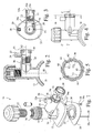
- a tapping tee assembly 10 comprises an integrally moulded saddle 12, body 14 and socket 16.
- the saddle 12 is provided with a saddle-shaped electrofusion element mat 18, which is attached thereto by over-moulding, snap-fit, screws or other fastening means such as terminal stud 38 and electrical connecting pin 28 as described further below.
- the body 14 has an axially extended screw threaded bore 20, and disposed within the bore, a metal cutter 15 having a screw threaded outer surface that cooperates with the screw thread of the bore 20.
- the socket 16 is adapted to receive a branch pipe or spigot (not shown) and is provided with an internal tubular spigot electrofusion element 22 (see Figures 2 and 3 ).
- the mat 18 is provided with a hole 32 adjacent the aperture 35 and through which the electrofusion element 30 passes from one side of said polymer material to the other. The ends of the wire are led to another hole 33 adjacent the outside rim of the mat 18.
- Socket electrofusion element 22 further comprises two electrical connectors in the form of a second electrical stud terminal 24 and a dovetailed anvil 26 (see Figure 3 ).
- the electrical stud 24 and dovetailed anvil 26 are connected to opposite ends of the socket electrofusion element 22, which is wound as a coil in the internal surface of the socket 16.
- the electrical stud terminal 24 is surrounded by an upstanding boss 27 forming a socket to receive the plug of an electrical connector of a power source.
- Said dovetailed anvil 26 electrically connects the two electrofusion elements 30,22 via said intermediate connecting pin 28.
- a similar socket 29 is provided for the stud 38, between terminal pins or studs 24,38 an electrical power source (not shown) may be connected to energise the two electrofusion elements 30,22.
- the circuit of the tapping tee assembly 10 comprises the upper and lower components of the electrofusion element 30 embedded in the saddle-shaped electrofusion mat 18 connected in parallel with one another, and in series with the socket electrofusion element 22 of the socket 16. Both pin 28 and stud 38 are provided with heads 28c,38c respectively in order to retain the mat 18 in place.
- a grip ring 50 On the end of the socket 16 is provided a grip ring 50.
- the end of the socket is formed with four fingers 52 separated from one another by slots 53.
- the slots are all parallel to enable shell moulds forming the exterior surface features of the tapping tee 10 to form them and yet simply split along a plane including the body 14 and the socket 16 (or at least their respective axes 80,82 - see Figure 2 ).
- the fingers have a proximal root end 52a and distal extreme end 52b.
- the fingers define an end-flange or ring-rib 54 which is chamfered at the ends 52b of the fingers, but is cut squarely at its proximal edge 54c, so as to lie in a plane radial with respect to the axis 82.
- a rear edge 56 at the root 52a of the fingers 52 is also radial and between that and the rib 54, an annular channel 58 is defined to receive the ring 50.
- the fingers 52 are provided with ribs 60, and the ring 50 with corresponding grooves 62.
- each of said ribs and grooves are provided at 90° to each other around the axis 82 and, when they coincide with each other, the internal face 52c of the fingers 52 remains circular cylindrical.
- Four shallow detent grooves 64 are also provided at 45° angles to the grooves 62.
- Grooves 62 and ribs 60 are conical in profile with their cone axes parallel the axis 82 and with their apex pointing at the body 14. When the ring is rotated about axis 82, the ribs and grooves come out of registration, deflecting the fingers 52 inwardly. Because of the coned profile of the ribs and grooves 60 the deflection of the fingers at their distal ends 52b is much greater than their deflection at their roots 52a. This avoids unnecessary shear stresses in the material at the fingers, and, in any event, ensures maximum deflection of the fingers.
- the groove 62 are provided with a shallow lead-in 62a. This is in the clockwise direction of rotation of the ring 50 on the socket 16 when viewed in the direction of the body 14.
- This lead-in reduces the angle of attack between the groove 62 and rib 60, which angle is the angle of the mating surfaces to the tangent of the base circular surface of the channel base 58. Consequently, less resistance is experienced by the user in turning the ring clockwise, this being the traditional tightening direction of rotation of screwed fittings.
- the ribs and grooves constituting mating cams and wedges surfaces, could be rotated in either direction, the only purpose being to de-register them so that the ribs 60 press against the internal circular (conical or cylindrical) surface 66 of the ring 50 (the surface 66 is cylindrical as shown).
- rotation in the anticlockwise direction would meet more resistance and would, in any event, be counter-intuitive to most users.
- One purpose of the grip ring 50 is to grip and hold pipes inserted in the socket 16 for electrofusion by the element 22.
- a pipe (not shown) when it is to be connected to the socket 16, is offered up to the outside surface with its end parallel mark 70 formed on the outside of the socket.
- a mark is then made on the pipe coincident with the ends 52b of the fingers 52 in order to show the required insertion of the pipe in the socket 16.
- the surface of the pipe is scraped to remove the oxidised skin of the said pipe.
- the pipe is then inserted until the mark made on the pipe is flush with the ends 52b and at this point the end of the pipe will abut a stop formed by end 26a of the anvil 26 (a rib may also, or instead, be formed to constitute the stop).
- the grip ring is then rotated to squeeze the fingers 52 against the pipe and clamp it in position.
- the fingers, particularly their ends 52b are spaced some distance from the electrofusion element 22 (preferably, but not essentially, at least one pipe diameter).
- the stop is preferably at least 2.25 pipe diameters from the end 52, with the effective end of the electrofusion element being about 2 pipes diameters from the end.
- the employment of the grip ring by users in the field is easy, so that even if it is unnecessary to employ in many instances, it will tend to be employed so that even rare failures of the joint formed can be avoided.
- misalignment of the pipe with the socket is minimised. Indeed, although having the substantial (ie one pipe diameter) separation between the ends of the fingers and the start of the electrofusion element is desirable, this substantial distance actually reduces the dependency on a centralising grip ring.
- the grip ring actually has most requirement, from this perspective, when the distance between finger ends and electrofusion element is necessarily small. It is small in many instances of standard electrofusion couplers where an increase in overall length of a coupler is prohibited by the need to accommodate short spigots of other fittings (eg T-pieces).
- Manufacture of the tapping tee assembly 10 requires injection moulding of a polymer material within a rigid mould that will not deform under temperatures around the melting point of said polymer material. Since the present invention comprises hollow tubes, a pair of moulding cores must be used within the main mould.
- the mould is not shown but comprises two or more shell moulds that form the external profile of the tapping tee 10, together with the core moulds, whereby a hollow product of relatively uniform wall thickness is formed.
- the component of the main mould that produces the saddle 12 component of the tapping tee assembly 10 comprises a core-pin (not shown) that forms a tunnel bore 68 extending upwards from the saddle 12, through the wall of body 14 parallel the main bore 20. Said element also prevents an eye 46 of said dovetailed anvil 26 from filling with polymer material during moulding.
- the hole 32 through said saddle-shaped electrofusion mat 18 is in line with the saddle end of said tunnel 66.
- the electrical connecting pin 28 can then be disposed in the tunnel 66 forming an electrical bridge between said saddle electrofusion element 30 of said saddle-shaped electrofusion mat 18 and said eye 46 of the dovetailed anvil 26.
- the saddle electrofusion element 18 and socket electrofusion element 22 are composed of a conducting material that produces sufficient heat to melt said fusible polymer material when an electrical current is passed through it, but does not itself melt or break.
- Said dovetailed anvil 26, electrical studs 24,38 and electrical connecting pin 28 are composed of a good electrically conducting material that does not produce significant heat when an electric current is passed through it.
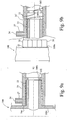
- the gripper ring assembly increases the overall length of a standard socket. Although a change in socket length does not affect the connection of a pipe, there are consequences when connecting shouldered spigot fittings designed for use with standard sockets, as shown in Figures 9a and b.
- a limit is reached when the shoulder 100a abuts the opening 16a of the socket 16 (and/or when the end 100b of the fitting 100 abuts an insertion limiting rib 102 of the socket 16).
- the shoulder 100a of a shouldered fitting 100 (designed for use with a standard length socket 16, is distanced from the end 100b of the fitting 100 to allow enough length to enter the socket 16 such that its end 100b extends beyond the end of the electrofusion element 22.
- the standard length now accepted for service pipe sizes is 41 mm for the depth of sockets and 42 mm for the length of spigots to be inserted in sockets.
- the shoulder 100a prevents the fitting 100 entering the socket 16' far enough to allow it to be surrounded by the entire electrofusion element 22. In such cases, only a poor electrofusion joint would be possible.
- the grip ring assembly must be added to the standard socket such that it does not increase its overall length.
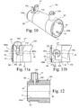
- Figure 10 discloses an inline coupler 104 in accordance with a modified embodiment of the present invention.
- This coupler is for joining two pipes (not shown) end-to-end, although the principles discussed below apply to any coupler, such as an elbow, T-joint or even a tapping tee.
- the coupler 104 has two internal electrofusion elements (not shown) connected in series to each other and to two terminal pins 24a,b.
- the terminal pins 24a,b project radially from the fingers 52 in between the slots 53 that define the fingers 52.
- Integral grip rings 50' attach over fingers 52 at both ends 104a,b of the inline coupler 104.
- the integral grip ring 50' is identical to the grip ring 50 described above, except that the integral grip ring 50' further comprises a slot 106, and an integral upstanding boss or shroud 27' coincident therewith.
- Figures 11a and b show how the terminal pin 24a passes through the slot 106 to finally be disposed within the boss 27'.
- the grip ring 50' is placed on the fingers 52 such that the terminal pin 24a passes through mouth 106a of the slot 106.
- the fingers 52 must deflect inward and the ribs 60 of the fingers 52 must register with the grooves 62 of the grip ring 50' (ribs 60 and grooves 62 not shown in Figures 11a,b ).
- the slot 106 is angularly positioned on the grip ring so that this registration of the ribs/grooves 60/62 is achieved when the mouth 106a of the slot engages the pin24a.
- the slot continues parallel the longitudinal axis 82 of the coupler until the point where the entire grip ring 50' has passed over the ring-rib 54 on the ends of the fingers 52.
- the grip ring 50' is restricted to only moving parallel the longitudinal axis 82 by contact between the terminal pin 24a and the sides of the slot 106.
- the ring-rib 54 of the fingers 52 and the shoulder 56 prevents further movement parallel the longitudinal axis 82.
- the terminal pin 24a has moved in the slot 106 such that only a transverse part 106b remains as an option for further movement.
- Figure 12 shows a cross sectional view of the grip ring 50' securely fastened around the terminal pin 24a (as in Figure 11 b) .
- the grip ring 50' With the upstanding boss 27' integral with the grip ring 50', the grip ring 50' can be incorporated further down the coupler 104, allowing the terminal pin 24 to pass through the slot 106 and be shrouded by the boss 27'.
- neither the terminal pin 24 nor boss 27' interferes with the positioning of the grip ring 50' and fingers 52.
- the integral grip ring therefore allows for the correct fitting of components that would otherwise be prevented from entering the socket sufficiently for a good electrofusion join to be made.
Landscapes
- Engineering & Computer Science (AREA)
- Mechanical Engineering (AREA)
- General Engineering & Computer Science (AREA)
- Lining Or Joining Of Plastics Or The Like (AREA)
- Branch Pipes, Bends, And The Like (AREA)
Priority Applications (5)
| Application Number | Priority Date | Filing Date | Title |
|---|---|---|---|
| PCT/GB2008/050580 WO2009010800A1 (en) | 2007-07-17 | 2008-07-16 | Electrofusion fitting |
| US12/669,455 US8424917B2 (en) | 2007-07-17 | 2008-07-16 | Electrofusion fitting |
| HK10104222.0A HK1137967B (en) | 2007-07-17 | 2008-07-16 | Electrofusion fitting |
| EP08776215.9A EP2178691B1 (de) | 2007-07-17 | 2008-07-16 | Elektroschweissmuffe |
| EG2010010066A EG26401A (en) | 2007-07-17 | 2010-01-13 | Installed for electrical fusion |
Applications Claiming Priority (1)
| Application Number | Priority Date | Filing Date | Title |
|---|---|---|---|
| GB0713814A GB2451081B (en) | 2007-07-17 | 2007-07-17 | Electrofusion fitting |
Publications (1)
| Publication Number | Publication Date |
|---|---|
| EP2017065A1 true EP2017065A1 (de) | 2009-01-21 |
Family
ID=38476390
Family Applications (2)
| Application Number | Title | Priority Date | Filing Date |
|---|---|---|---|
| EP07254750A Withdrawn EP2017065A1 (de) | 2007-07-17 | 2007-12-07 | Elektrofusionsverbindungsmanschette |
| EP08776215.9A Not-in-force EP2178691B1 (de) | 2007-07-17 | 2008-07-16 | Elektroschweissmuffe |
Family Applications After (1)
| Application Number | Title | Priority Date | Filing Date |
|---|---|---|---|
| EP08776215.9A Not-in-force EP2178691B1 (de) | 2007-07-17 | 2008-07-16 | Elektroschweissmuffe |
Country Status (5)
| Country | Link |
|---|---|
| US (1) | US8424917B2 (de) |
| EP (2) | EP2017065A1 (de) |
| EG (1) | EG26401A (de) |
| GB (1) | GB2451081B (de) |
| WO (1) | WO2009010800A1 (de) |
Cited By (1)
| Publication number | Priority date | Publication date | Assignee | Title |
|---|---|---|---|---|
| EP2617552A1 (de) | 2011-09-07 | 2013-07-24 | Radius Systems Limited | Verbesserte integrierte Leitungsgreifvorrichtung |
Families Citing this family (8)
| Publication number | Priority date | Publication date | Assignee | Title |
|---|---|---|---|---|
| GB2451081B (en) * | 2007-07-17 | 2009-09-09 | Uponor Innovation Ab | Electrofusion fitting |
| US11628267B2 (en) | 2010-08-04 | 2023-04-18 | Medline Industries, Lp | Universal medical gas delivery system |
| US9316336B2 (en) * | 2012-04-16 | 2016-04-19 | Nupi Industrie Italiane S.P.A. | Penetration fitting unit for seal-connection between a wall and a pipe passing through |
| ES2669743T3 (es) | 2014-01-30 | 2018-05-29 | Plasson Ltd | Elemento de acoplamiento por electrofusión y proceso de fabricación de elemento de acoplamiento por electrofusión |
| US20150210823A1 (en) | 2014-01-30 | 2015-07-30 | Plasson Ltd. | Electrofusion coupler composition |
| ITUA20162246A1 (it) * | 2016-04-01 | 2017-10-01 | Nupi Ind Italiane S P A | Raccordo a sella elettrosaldabile e relativo metodo di saldatura. |
| US9791085B2 (en) | 2015-03-11 | 2017-10-17 | Robert J. Morrow | Method of joining pipes and apparatus for facilitating the same |
| CN110578872A (zh) * | 2019-08-28 | 2019-12-17 | 诸暨市逍遥管道科技有限公司 | 一种用于监测非金属管道泄漏的系统及方法 |
Citations (3)
| Publication number | Priority date | Publication date | Assignee | Title |
|---|---|---|---|---|
| US3506519A (en) * | 1967-01-13 | 1970-04-14 | Susquehanna Corp | Method of making interlocked welded connections between thermoplastic articles |
| EP0525339A1 (de) * | 1991-07-22 | 1993-02-03 | Georg Fischer Rohrleitungssysteme AG | Formteil aus thermoplastischem Material |
| DE4437407A1 (de) * | 1994-10-19 | 1996-04-25 | Gruber Alois Agru Gmbh | Schweißmuffe zum Verbinden von Kunststoffrohrteilen |
Family Cites Families (15)
| Publication number | Priority date | Publication date | Assignee | Title |
|---|---|---|---|---|
| GB891392A (en) * | 1958-03-14 | 1962-03-14 | Martin James | A new or improved connector for releasably and fluid-tightly coupling conduits |
| DE2856895A1 (de) * | 1978-12-30 | 1980-07-17 | Dynamit Nobel Ag | Pyrotechnische schweissmuffe zur verbindung von formteilen, insbesondere rohren, aus thermoplastischem kunststoff |
| CH671444A5 (de) * | 1986-06-25 | 1989-08-31 | Fischer Ag Georg | |
| US5150922A (en) * | 1989-01-11 | 1992-09-29 | Osaka Gas Co., Ltd. | Electrofusion joint and hot water supply header using the same |
| US4958857A (en) * | 1989-01-30 | 1990-09-25 | R&G Sloane Manufacturing Co. | Welding seal assembly |
| CH687640A5 (de) * | 1994-04-29 | 1997-01-15 | Fischer Georg Rohrleitung | Verbindungsformteil fuer Abzweiganschluesse bei einer Rohrleitung. |
| DE19500579C2 (de) * | 1995-01-11 | 1998-05-07 | Fischer Georg Rohrleitung | Formteil aus thermoplastischem Material |
| EP1054206B1 (de) * | 1996-01-24 | 2003-11-26 | Uponor Aldyl Company | Vorrichtung und Verfahren zum Verbinden durch Schmelzen von einem Rohr mit Kupplungsstücken |
| DE29619861U1 (de) * | 1996-11-07 | 1997-03-06 | GAWATEC Rohrverbindungssysteme GmbH & Co. KG, 49406 Barnstorf | Kunststoff-Schweißmuffe |
| GB2319576B (en) * | 1996-11-20 | 2001-02-07 | Uponor Bv | Pipe connector |
| US6250686B1 (en) * | 1999-01-25 | 2001-06-26 | Zurn Industries, Inc. | Combination mechanical/fusion pipe fitting |
| DE19927778C1 (de) * | 1999-06-17 | 2000-10-19 | Friatec Ag | Schweißmuffe |
| AU780812B2 (en) * | 1999-09-14 | 2005-04-21 | Georg Fischer Wavin Ag | Improved welding socket |
| GB2451081B (en) * | 2007-07-17 | 2009-09-09 | Uponor Innovation Ab | Electrofusion fitting |
| GB2451080B (en) * | 2007-07-17 | 2011-10-05 | Uponor Innovation Ab | Tapping tee assembly |
-
2007
- 2007-07-17 GB GB0713814A patent/GB2451081B/en not_active Expired - Fee Related
- 2007-12-07 EP EP07254750A patent/EP2017065A1/de not_active Withdrawn
-
2008
- 2008-07-16 EP EP08776215.9A patent/EP2178691B1/de not_active Not-in-force
- 2008-07-16 US US12/669,455 patent/US8424917B2/en not_active Expired - Fee Related
- 2008-07-16 WO PCT/GB2008/050580 patent/WO2009010800A1/en not_active Ceased
-
2010
- 2010-01-13 EG EG2010010066A patent/EG26401A/en active
Patent Citations (3)
| Publication number | Priority date | Publication date | Assignee | Title |
|---|---|---|---|---|
| US3506519A (en) * | 1967-01-13 | 1970-04-14 | Susquehanna Corp | Method of making interlocked welded connections between thermoplastic articles |
| EP0525339A1 (de) * | 1991-07-22 | 1993-02-03 | Georg Fischer Rohrleitungssysteme AG | Formteil aus thermoplastischem Material |
| DE4437407A1 (de) * | 1994-10-19 | 1996-04-25 | Gruber Alois Agru Gmbh | Schweißmuffe zum Verbinden von Kunststoffrohrteilen |
Cited By (1)
| Publication number | Priority date | Publication date | Assignee | Title |
|---|---|---|---|---|
| EP2617552A1 (de) | 2011-09-07 | 2013-07-24 | Radius Systems Limited | Verbesserte integrierte Leitungsgreifvorrichtung |
Also Published As
| Publication number | Publication date |
|---|---|
| EG26401A (en) | 2013-10-09 |
| GB2451081B (en) | 2009-09-09 |
| GB0713814D0 (en) | 2007-08-29 |
| HK1137967A1 (en) | 2010-08-13 |
| EP2178691A1 (de) | 2010-04-28 |
| WO2009010800A1 (en) | 2009-01-22 |
| EP2178691B1 (de) | 2015-09-02 |
| US8424917B2 (en) | 2013-04-23 |
| GB2451081A (en) | 2009-01-21 |
| US20100207382A1 (en) | 2010-08-19 |
Similar Documents
| Publication | Publication Date | Title |
|---|---|---|
| US8424917B2 (en) | Electrofusion fitting | |
| US4958857A (en) | Welding seal assembly | |
| US8398119B2 (en) | Electrofusion fitting | |
| US6131954A (en) | Weldable couple for electrofusion coupling of profile wall thermoplastic pipes without a separate coupler | |
| EP2215394B1 (de) | Anzapf-t-anordnung | |
| EP2617552B1 (de) | Elektroschweißmuffe | |
| US20060214418A1 (en) | Arrangement with a tubular element | |
| AU641841B2 (en) | Pipe joints | |
| EP1214545B1 (de) | Verbesserte schweissmuffe | |
| US6521072B1 (en) | Method of coupling profile wall thermoplastic pipes | |
| EP1432944B1 (de) | Rohrverbindungen | |
| WO1995007432A1 (en) | Improvements in or relating to pipe fittings | |
| HK1137967B (en) | Electrofusion fitting | |
| JP5400367B2 (ja) | 電気融着継手 | |
| JP2011117563A (ja) | 電気融着継手 | |
| JP2021055745A (ja) | 継手 | |
| GB2284179A (en) | Electrofusion coupling element | |
| JP7365176B2 (ja) | 継手 | |
| JP6001373B2 (ja) | 電気融着継手 | |
| JP7689853B2 (ja) | クランプ及び電気融着継手ユニット | |
| JP7601351B2 (ja) | 電気融着継手の製造方法 | |
| JPH08270873A (ja) | 電気融着継手 | |
| JP2018173147A (ja) | 樹脂管同士の仮固定構造 | |
| JP2009270684A (ja) | エレクトロフュージョン継手 | |
| JP2023055439A (ja) | 電気融着継手 |
Legal Events
| Date | Code | Title | Description |
|---|---|---|---|
| PUAI | Public reference made under article 153(3) epc to a published international application that has entered the european phase |
Free format text: ORIGINAL CODE: 0009012 |
|
| AK | Designated contracting states |
Kind code of ref document: A1 Designated state(s): AT BE BG CH CY CZ DE DK EE ES FI FR GB GR HU IE IS IT LI LT LU LV MC MT NL PL PT RO SE SI SK TR |
|
| AX | Request for extension of the european patent |
Extension state: AL BA HR MK RS |
|
| AKX | Designation fees paid | ||
| REG | Reference to a national code |
Ref country code: DE Ref legal event code: 8566 |
|
| STAA | Information on the status of an ep patent application or granted ep patent |
Free format text: STATUS: THE APPLICATION IS DEEMED TO BE WITHDRAWN |
|
| 18D | Application deemed to be withdrawn |
Effective date: 20090722 |