EP2017107A1 - Store pour ombrager doté d'un verrouillage - Google Patents
Store pour ombrager doté d'un verrouillage Download PDFInfo
- Publication number
- EP2017107A1 EP2017107A1 EP08011898A EP08011898A EP2017107A1 EP 2017107 A1 EP2017107 A1 EP 2017107A1 EP 08011898 A EP08011898 A EP 08011898A EP 08011898 A EP08011898 A EP 08011898A EP 2017107 A1 EP2017107 A1 EP 2017107A1
- Authority
- EP
- European Patent Office
- Prior art keywords
- roller blind
- linear guide
- blocking device
- guide means
- blind according
- Prior art date
- Legal status (The legal status is an assumption and is not a legal conclusion. Google has not performed a legal analysis and makes no representation as to the accuracy of the status listed.)
- Granted
Links
Images


Classifications
-
- E—FIXED CONSTRUCTIONS
- E06—DOORS, WINDOWS, SHUTTERS, OR ROLLER BLINDS IN GENERAL; LADDERS
- E06B—FIXED OR MOVABLE CLOSURES FOR OPENINGS IN BUILDINGS, VEHICLES, FENCES OR LIKE ENCLOSURES IN GENERAL, e.g. DOORS, WINDOWS, BLINDS, GATES
- E06B9/00—Screening or protective devices for wall or similar openings, with or without operating or securing mechanisms; Closures of similar construction
- E06B9/56—Operating, guiding or securing devices or arrangements for roll-type closures; Spring drums; Tape drums; Counterweighting arrangements therefor
- E06B9/58—Guiding devices
-
- B—PERFORMING OPERATIONS; TRANSPORTING
- B60—VEHICLES IN GENERAL
- B60J—WINDOWS, WINDSCREENS, NON-FIXED ROOFS, DOORS, OR SIMILAR DEVICES FOR VEHICLES; REMOVABLE EXTERNAL PROTECTIVE COVERINGS SPECIALLY ADAPTED FOR VEHICLES
- B60J1/00—Windows; Windscreens; Accessories therefor
- B60J1/20—Accessories, e.g. wind deflectors, blinds
- B60J1/2011—Blinds; curtains or screens reducing heat or light intensity
- B60J1/2013—Roller blinds
- B60J1/2033—Roller blinds characterised by the spring motor
-
- B—PERFORMING OPERATIONS; TRANSPORTING
- B60—VEHICLES IN GENERAL
- B60J—WINDOWS, WINDSCREENS, NON-FIXED ROOFS, DOORS, OR SIMILAR DEVICES FOR VEHICLES; REMOVABLE EXTERNAL PROTECTIVE COVERINGS SPECIALLY ADAPTED FOR VEHICLES
- B60J1/00—Windows; Windscreens; Accessories therefor
- B60J1/20—Accessories, e.g. wind deflectors, blinds
- B60J1/2011—Blinds; curtains or screens reducing heat or light intensity
- B60J1/2013—Roller blinds
- B60J1/2066—Arrangement of blinds in vehicles
- B60J1/2086—Arrangement of blinds in vehicles specially adapted for openable windows, e.g. side window
Definitions
- the invention relates to a shading roller blind for a motor vehicle window with a flexible sheet which can be wound up and unwound on a winding shaft and which can be moved from a stowed position into an at least partially unwound protective position by means of at least one linear guide means.
- Shading blinds may be provided on rear windows, side windows and / or panorama windows of vehicles.
- the flexible fabric also referred to as roller blind, is designed according to the requirements of a suitable material.
- For unwinding of the flexible sheet of the winding shaft it is known, for example, to connect at a free end of the flexible sheet a drawer or a pull-out profile with the flexible sheet, which preferably extends over the entire width of the sheet.
- the pull-out strip or the pull-out profile is provided by suitable means, for example scissor or swivel arms, kink-resistant antennas, guided in guide rails racks or central telescopic arms movable.
- a drive of this linear guide means for example, electrically, pneumatically and / or hydraulically.
- a shading roller blind for a motor vehicle windshield with a flexible sheet that can be wound on a winding shaft and is movable from a stowage position into an at least partially unwound protective position by means of at least one linear guide means, and with a releasable blocking device, by means of which the Linear guide means at least in one position, in particular the protective position and / or the stowed position can be locked, wherein the blocking device comprises a push-push-lock.
- push-push-locking is an actuating mechanism which works according to a so-called ballpoint pen principle called.
- a locking and releasing the blocking device is realized by applying a force always in the same direction of actuation and / or a movement corresponding to the force.
- the force is at first a compressive force.
- the push-push locking for example, a withdrawal or unwinding of the blind is prevented.
- the blocking device locks a winding of the roller blind.
- the linear guide means in the stowed position can be locked, wherein the blocking device by applying a force, in particular a compressive force, on the linear guide means and / or moving the linear guide means against a Abwickelides is solvable.
- a force in particular a compressive force
- a tensile force necessary for unwinding.
- the restoring force necessary for winding can be used.
- the release or locking force is preferably applied in a simple manner by pressing the linear guide means and / or parts thereof against the unwinding direction.
- the blocking device is at least partially disposed on a housing or the like of the winding shaft, wherein the shade according to the invention can be designed as a compact unit, which in a pre-assembly assembled and tested. The tested unit can be installed as a component in a motor vehicle.
- any linear guide means can be used, for example, lateral guide rails, pivot arms and / or centrally arranged actuating rods are conceivable.
- an effective in the unwinding mechanical drive means is provided, by the flexible sheet of the winding shaft can be unwound after a release of the blocking device. Since the drive means only in one direction, namely the unwinding, is effective, a corresponding arrangement is also referred to as semi-automatic.
- a winding of the flexible sheet is done manually in an embodiment, wherein preferably a return spring or the like is provided on the winding shaft, which is ensured by the fact that the flexible sheet is rolled up compactly on the winding shaft.
- the mechanical drive means is designed as a spring-loaded arrangement.
- the spring-loaded arrangement comprises a compression spring, for example a helical compression spring, or a tension spring. A winding of the flexible sheet takes place against an action of the spring, wherein the unwinding of the flexible sheet so stored force acts on the linear guide means.
- the blocking device comprises at least one latching element which cooperates with the linear guide means for a locking.
- a counter-locking element can be arranged on the pull-out profile or on other elements.
- a latching element is provided on the linear guide means.
- the linear guide means comprises a guide with a guide groove, in which the latching element is guided, wherein the guide groove has at least one latching point.
- the locking point is designed to be complementary to the locking element, so that this is latched there.
- the latching element is mounted so as to be displaceable on the blocking device transversely to the unwinding direction, in particular at a right angle thereto. This results in particularly advantageous possibilities for the design of the guide.
- the guide groove has the shape of a heart curve, at least in sections. Such a shape has proven to be particularly advantageous for the realization of a push-push lock.
- a blocking device with a push-push lock is alternatively or additionally provided, whose actuating direction extends transversely to the unwinding direction, in particular at an angle of about 90 ° to this.
- an operation switch or button may be provided, wherein by pressing the button, a lock and / or unlocking is possible.
- the shade is preferably equipped with a semi-automatic.
- a return spring is provided, wherein the roller blind can be manually extended against the force of the return spring and in any extended position, in particular in a protective position, can be locked. By loosening the blocking device, the roller blind is pulled in automatically by the force of the return spring.
- an effective in unwinding drive means for example a spring-loaded arrangement, wherein after releasing the blocking device, the roller blind is unwound by the drive means becomes.
- a element which can be actuated by pulling force such as a loop or the like, can be provided, wherein a locking and releasing takes place by applying a force in an actuating direction.
- the linear guide means comprises at least one pivotable switch and the blocking device at least one movable switching element for actuating the switch, wherein the switch and the switching element cooperate for locking the linear guide means.
- the switching element By the switching element, the switch is pivoted to lock or release.
- the switching element has an attack surface for a user in one embodiment, wherein by applying a force on the engagement surface, the switching element is pivotable and thus the linear guide means can be locked.
- the blocking device comprises a drive.
- the switching element for locking and / or for releasing the lock is movable in one embodiment. Since only a small travel is required, the drive can be made much more compact, as a necessary for winding and / or unwinding of the roller blind over the entire length drive.
- the drive can be operated remotely, so that, for example, a shading or protective roller blind provided in the rear area can easily be opened and / or unwound by a driver.
- the linear guide means comprises at least one rod, which is operatively connected to an extension profile attached to the flexible sheet material for a movement transmission.
- the pull-out profile is preferably attached to a free edge of the flexible sheet, with a Attachment can be fixed or floating.
- the pull-out profile can extend over the entire width of the flexible sheet.
- the pull-out profile can be created as a rod or the like, for example made of metal or plastic. In other embodiments, the pull-out profile is realized in one piece with the flexible fabric as reinforcement.
- the linear guide means comprises at least one telescopic rod, which is operatively connected to the attached to the flexible sheet extract profile for the transmission of movement.
- the telescopic rod is transferred in one embodiment by the spring-loaded assembly in an extended or a collapsed position, the telescopic rod in the collapsed position requires little space.
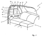
- FIG. 1 schematically shows a rear portion of a motor vehicle 1 in a partially cutaway, perspective view overlooking the inside of a rear, right side door 2.
- the motor vehicle 1 has a vehicle roof 10, from the side a B-pillar 11 of the motor vehicle 1 to a not shown Floor group leads.
- a corresponding B-pillar on the FIG. 1 not shown left side of the motor vehicle 1 is provided.
- the illustrated motor vehicle 1 further comprises a C-pillar 12.
- the roof 10 is at a trailing edge in a frame of a rear window opening 13, in which a rear window, not shown, can be used.
- the right, rear side door 2 is mounted in a known manner, in particular by means not shown hinges.
- At the height of the side door 2 is a rear seat 3.
- an interior of the motor vehicle 1 facing inside of the side door 2 has an inner lining 20.
- a door handle 21 and an actuating pawl 22 are provided for a door lock, not shown.
- Other elements, not shown, such as speakers and the like, may also be integrated into the side door 2 and / or attached thereto.
- the side door 2 has a window opening 23, which is divided into a first section 24 and a second section 25 by a web 26.
- the second section 25 is designed as an opening for a so-called triangular window, so that the window opening 23 is substantially trapezoidal.
- the window opening 23 has a lower edge 27 and an upper edge 28, wherein the upper edge 28 is usually not parallel to the lower edge 27, but may extend curved.
- a non-illustrated, two-part side window can be used.
- the side window is usually displaceable at least in the first section 24.
- the window opening 23 can be further darkened by an inventive shade blind, which is designed in the embodiment as a side window blind 4 with a blind sheet 40.
- a shading blind according to the invention serves to cover the rear window opening 13.
- the pullout 50 is attached to a free edge of the blind sheet 40 and movable by means of the rod 51.
- the pull-out profile 50 is guided in lateral guide rails.
- Fig. 2 schematically shows the side door 2 according to Fig. 1 , Uniform reference symbols are used for the same components and a detailed description of these components will be omitted.
- the side window roller blind 4 comprises a winding shaft 43, on which the roller blind 40 is fastened up and unwound.
- the blind sheet 40 is only partially processed.
- the roller blind 40 is at Winding on the winding shaft 43 via a slot 29 behind the inner panel 20 of the side door 2 retractable.
- the roller blind 40 is retractable in an advantageous embodiment completely behind the inner lining 20, but the pull-out profile 50 protrudes at least partially visible.
- the illustrated pull-out profile 50 is curved at least in sections, so that the pull-out profile 50 can be adapted to the course of the upper edge 28 of the window opening 23 to be covered. As a result, a good darkening of the associated side window in the edge area is possible.
- the pull-out profile 50 is operatively connected to the rod 51 for moving the pull-out profile 50 and thus for unwinding the roller blind 40 from the winding shaft 43.
- the rod 51 is at least partially retractable in a hollow tube 52.
- the rod 51 and / or the hollow tube 52 needs / require some small space on the side door 2 and can / can be so easily integrated into this.
- a spring such as a helical compression spring 6 is compressed.
- the helical compression spring 6 acts as a mechanical drive means, wherein an unwinding of the roller blind 40 can take place due to the spring force of the helical compression spring 6 and / or is supported thereby.
- the pull-out profile is guided in one or two lateral guide rail (s), wherein a spring for unwinding the roller blind can be provided in the guide rail.
- a return spring for winding the roller blind 40 on the winding shaft 43 .
- a blocking device 7 is provided according to the invention.
- the blocking device 7 according to the invention comprises a push-push lock, so that the rod 51 and / or the pull-out profile 50 can be locked at least in a stowed position of the roller blind 40, the lock being releasable by pressing and / or moving counter to the unwinding direction ,
- the blocking device 7 acts with the rod 51 together.
- the blocking device 7 comprises an in Fig. 2 not shown locking element, which cooperates with the linear guide means 5 in a stowed position of the blind sheet 40 for locking.
- Fig. 3a and 3b schematically show a guide groove 54 of a push-push latch.
- the guide groove 54 or backdrop is at least partially designed as a heart curve.
- latching element 70 In the guide groove 54 is a on the blocking device 7 according to Fig. 2 arranged latching element 70 out.
- the locking element 70 is, as shown by the arrows, mounted displaceably in the blocking device 7 in a direction transverse to the unwinding direction A.
- the guide groove 54 is for example on the pullout profile 50 or the rod 51 according to Fig. 2 educated. To lock the pull-out profile 50 and / or the rod 51 and thus the guide groove 54 is moved by applying a compressive force P against the unwinding A, in the representation down.
- the locking element 70 is deflected by the slope of a formed in the guide groove 54 counter-latching element 55, in the illustrated embodiment to the left.
- the force for moving the rod 51 and / or the Auszugprofils 50 can be reduced, the rod 51 and thus the guide groove 54, for example, due to the force of the helical compression spring 6 Fig. 2 in the unwinding A, in the representation upwards, is moved.
- the latching element 70 comes into engagement with the counter-latching element 55 at a latching point 57.
- the latching element 70 interacts with the counter-latching element 55 in such a way that the movement of the pull-out profile 50 and / or the rod 51 in the unwinding direction A is prevented.
- the guide groove is moved downwards in the illustration and the latching element 70 is laterally deflected due to the shape of the guide groove 54.
- the deflection takes place in the illustrated Embodiment to the right.
- an interaction of the latching element 70 with the counter-latching element 55 and thus the blocking device 7 according to Fig. 2 solved.
- an actuating force can be removed, whereby the roller blind 40 is extended due to the force of the helical compression spring 6, that is moved in the unwinding A.
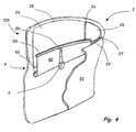
- Fig. 4 schematically shows the side door 2 according to Fig. 1 with a side window blind 4 according to a second embodiment of the invention.
- An actuating device 105 for the side window roller blind 4 comprises a telescopic rod 151 which acts on the pull-out profile 50, so that the pull-out profile 50 in the illustrated embodiment is movable in the direction of the upper edge 28 of the window opening 23 for unwinding the roller blind 40.
- the illustrated telescopic rod 151 is represented by a in Fig. 4 not visible helical compression spring or the like extended.
- a blocking device 7 according to the invention is also provided. The blocking device 7 is designed such that the side window blind 4 is gradually unwound.
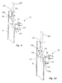
- Fig. 5 schematically shows a side window blind 204 according to a third embodiment of the invention.
- the side window roller blind 204 is also one at the level of a schematically indicated lower edge 27 only schematically indicated side door 2 retractable.
- a linear guide means 205 for the side window roller blind 204 comprises the pull-out profile 250, as well as a rod 251 or antenna arranged laterally on the roller blind 40.
- the rod 251 is guided at least in the region of the side door 2 in a guide rail 8.
- the rod 251 and thus the roller blind 40 are locked by a blocking device 207 in the position shown, which is in the illustrated embodiment, the protective position of the blind sheet 40.
- the blocking device 207 comprises a pivotable switch 71, which is pivotally mounted on the rod 251, and a pivotable switching element 72, through which the switch 71 is actuated.
- the width of the switch 71 is approximately equal to or less than the width of the rod 251, wherein the switch 71 for moving the rod 251 can be arranged in alignment with the rod 251.
- the switch 71 is further pivotable in the illustrated position, wherein a longitudinal axis of the switch 71 with the longitudinal axis of the rod 251 forms an angle. In the in Fig. 5 As shown, the switch 71 is forced in a direction shown by the arrow X by a return force FR acting on the roller blind downwardly in the illustration.
- a counter spring 74 is further provided, which loads the switching element 72 and thereby forces the switch 71 in the direction shown by the arrow X direction. In such a forced oblique position of the switch 71, the switch 71 is held between the switching element 72 and a door-side counter-latching element 73, so that pivoting against the direction shown by the arrow X for aligning the switch 71 with the rod 251 is prevented.
- the illustrated blocking device 207 further comprises a drive 75 with a piston 76, by means of which the switching element 72 can be actuated.
- the drive 75 is designed for example with a servomotor, so that an operation by a driver is remotely possible.
- a setting knob 77 may be provided, through which the switching element 72 is actuated.
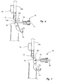
- Fig. 6 and Fig. 7 schematically show an operation of the blocking device 207 according to Fig. 5 .
- a force P is applied by the servo motor 75 and / or the knob 77, wherein the switching element 72 is actuated against the force FS of the opposing spring 74, is pivoted in the illustrated embodiment.
- the switching element 72 acts on its button 720 in such a way with the switch 71 that the switch 71 is pivoted, so that the switch 71 is aligned with the rod 251.
- the switching element 72 is pivoted to a contact with the switch 71 at a turning point 721, which is formed in the illustrated embodiment by a tip of the switching element 72 on the button 720.
- the switch 71 is turned on by the switching element 72 as in FIG Fig. 7 can be seen held in the aligned arrangement, so that the rod 251 slidably and thus the blind sheet is wound up.
- the blocking device 207 blocks unwinding of the roller blind 40.
- a remote-controlled release and / or locking of the blocking device 207 is possible.
- a small travel is necessary and / or apply a small force.
- the drive means for the roller blind 40 after releasing the blocking device 207 is an automatic unwinding, for example due to a force of a spring-loaded arrangement, or an automatic winding, for example, due to a force of a return spring shading blinds.
- the blocking device 307 is similar to the blocking device 207 according to FIG Fig. 5 trained and the same or similar components, the same or similar reference numerals are used.
- the blocking device 307 comprises a pivotable switching head 171, which is pivotable on the rod 251 of the side window roller blind 204 according to FIG Fig. 5 is appropriate.
- the switching head 171 has four concave corners 771 and four convex corners 772, which are arranged alternately, wherein by connecting the convex corners 772 of the switching head 171, a rectangle with a longitudinal side a and a broadside b can be formed.
- the blocking device 307 further comprises a vehicle-mounted, pivotable contact piece 172, through which the switching head 171 is actuated.
- the switching piece 172 is loaded at one end by a spring 174 with the force FS.
- a piston 76 of a holding magnet 75 is mounted, wherein the switching piece 172 is pivotable about an axis arranged between the ends.
- the rod 251 and thus the side window roller blind 204 in the direction indicated by the arrow Y from the guide rail 8 can be extended.
- An extension is possible until the switching head 171 reaches a provided on the guide rail 8 counter-locking element 173, this position is also referred to as the switching point.
- the counter-latching element 173 is arranged so that a tip 730 abuts upon reaching the switching point on an edge of an upper concave corner 771, so that the switching head 171 is pivoted to a locking position.
- the spring 174 171 and the switching element 172 can be pivoted after the elimination of the contact force between the contact piece 172 and switching head 171 due to the force FS of the spring 174.
- pivoting counterclockwise would be conceivable (not shown).
- the piston 76 in the position shown on the stop, so that no further pivoting is possible.
- the side window blind 204 can be moved, for example, by eliminating the pull-out force due to gravity against the extension direction down.
- the switching head 171 locks with two diagonally opposite convex corners 772, 772a between a wall of the guide rail 8 and the contact piece 172.
- the contact piece 172 is held by the spring 174 and the switching head 172 in the position shown.
- Fig. 11 shows the blocking device 307 when releasing the locking.
- a force is applied by the holding magnet 75, so that the switching piece 172 pivots against the force FS of the spring 174.
- the switching head 171 is pivoted and / or moved so that the latching is released.
- the spring 174 is designed so that it loads the switching piece 172 in a clockwise direction, wherein by the holding magnet 75, a counter force is applied, which is reduced or removed to release the latching.
- Fig. 12 shows the blocking device 307 when retracting the side window roller blind 204 after releasing the locking, wherein the switching piece 172 is pivoted back again after elimination of the force applied by the holding magnet 75 force.
- This locking and unlocking according to the FIGS. 8 to 12 is also referred to as push-push locking in the context of the invention.
- the force is applied to lock on a broad side a of the switching head 171 and the force for unlocking on the longitudinal side b of the switching head 172, wherein a short-term force application causes a locking or unlocking.
- a blocking device according to the FIGS. 8 to 12 be used for locking in a stowed position, wherein the elements are to be arranged mirrored about a horizontal axis.
- the movement from the shift position according to Fig. 9 in the locked position according to Fig. 10 takes place in the illustrated embodiment by the weight.
- the weight Likewise, for locking according to Fig. 10 used the weight.
- a force corresponding to the action of the force of gravity is to be applied by a spring, for example a spring-loaded arrangement for extending the roller blind.
Landscapes
- Engineering & Computer Science (AREA)
- Mechanical Engineering (AREA)
- Structural Engineering (AREA)
- Architecture (AREA)
- Civil Engineering (AREA)
- Operating, Guiding And Securing Of Roll- Type Closing Members (AREA)
Applications Claiming Priority (1)
| Application Number | Priority Date | Filing Date | Title |
|---|---|---|---|
| DE102007035043A DE102007035043A1 (de) | 2007-07-20 | 2007-07-20 | Beschattungsrollo mit Rolloverriegelung |
Publications (2)
| Publication Number | Publication Date |
|---|---|
| EP2017107A1 true EP2017107A1 (fr) | 2009-01-21 |
| EP2017107B1 EP2017107B1 (fr) | 2011-03-02 |
Family
ID=39047418
Family Applications (1)
| Application Number | Title | Priority Date | Filing Date |
|---|---|---|---|
| EP08011898A Not-in-force EP2017107B1 (fr) | 2007-07-20 | 2008-07-02 | Store pour ombrager doté d'un verrouillage |
Country Status (6)
| Country | Link |
|---|---|
| US (1) | US20090020236A1 (fr) |
| EP (1) | EP2017107B1 (fr) |
| JP (1) | JP2009023648A (fr) |
| KR (1) | KR101605841B1 (fr) |
| CN (1) | CN101349141B (fr) |
| DE (3) | DE102007035043A1 (fr) |
Cited By (1)
| Publication number | Priority date | Publication date | Assignee | Title |
|---|---|---|---|---|
| DE102014211617B4 (de) | 2013-06-28 | 2019-07-04 | Bos Gmbh & Co. Kg | Beschattungsvorrichtung für einen Glasflächenbereich eines Kraftfahrzeugs |
Families Citing this family (18)
| Publication number | Priority date | Publication date | Assignee | Title |
|---|---|---|---|---|
| DE102008020541A1 (de) * | 2008-04-24 | 2009-10-29 | GM Global Technology Operations, Inc., Detroit | Sonnenblendschutzvorrichtung für die Fensterscheibe eines Kraftfahrzeugs und Kraftfahrzeug mit einer solchen Sonnenblendschutzvorrichtung |
| DE102008063775A1 (de) * | 2008-12-18 | 2010-07-01 | Audi Ag | Fahrzeugfensterrollo |
| DE102009038185A1 (de) * | 2009-08-20 | 2011-02-24 | GM Global Technology Operations, Inc., Detroit | Kraftfahrzeug mit Windschutzscheibe, separater Dachscheibe und ausziehbarem Rollo |
| KR101106937B1 (ko) * | 2010-01-13 | 2012-01-19 | (주)수퍼플랫 | 가로등 설치용 조명 장치 |
| TW201139173A (en) * | 2010-05-06 | 2011-11-16 | Macauto Ind Co Ltd | Semi-automatic type sunshade curtain device |
| CN102606056A (zh) * | 2011-01-19 | 2012-07-25 | 皇田工业股份有限公司 | 半自动式遮阳帘装置 |
| US20130020040A1 (en) * | 2011-07-20 | 2013-01-24 | Paul Lin | Sunshade Assembly Having a Locking Mechanism |
| DE102012204592A1 (de) * | 2012-03-22 | 2013-09-26 | Schaeffler Technologies AG & Co. KG | Drehverbindung |
| JP5985239B2 (ja) * | 2012-04-26 | 2016-09-06 | 芦森工業株式会社 | シェード装置 |
| DE102014004247B4 (de) | 2014-03-25 | 2017-08-17 | Lisa Dräxlmaier GmbH | Arretierungseinrichtung mit einer Mehrzahl von Haltepositonen |
| KR101601497B1 (ko) | 2014-10-02 | 2016-03-08 | 현대자동차주식회사 | 차량용 롤러블라인드 커튼장치 |
| US10336165B2 (en) | 2015-05-01 | 2019-07-02 | Ford Global Technologies, Llc | Spring-activated extendable sun visor blade |
| JP6629049B2 (ja) * | 2015-11-18 | 2020-01-15 | 芦森工業株式会社 | 車両用シェード装置 |
| US10661638B2 (en) * | 2016-06-24 | 2020-05-26 | Macauto Industrial Co., Ltd | Shade arrangement for vehicle |
| CN105952363B (zh) * | 2016-06-24 | 2018-11-23 | 深圳品彦室内设计有限公司 | 一种卷帘自开启系统 |
| DE102016111658B4 (de) * | 2016-06-24 | 2022-07-21 | Macauto Industrial Co., Ltd. | Verschattungsvorrichtung für ein Fahrzeug |
| WO2020252253A1 (fr) | 2019-06-12 | 2020-12-17 | Shanghai Yanfeng Jinqiao Automotive Trim Systems Co. Ltd. | Pièce de véhicule |
| DE102019004378A1 (de) | 2019-06-19 | 2019-12-19 | Daimler Ag | Rollo für ein Kraftfahrzeug |
Citations (6)
| Publication number | Priority date | Publication date | Assignee | Title |
|---|---|---|---|---|
| DE19806736A1 (de) * | 1998-02-18 | 1999-08-26 | Baumeister & Ostler Gmbh Co | Schutzvorrichtung für eine Scheibe eines Kraftfahrzeugs |
| DE20112948U1 (de) | 2001-07-27 | 2001-10-25 | BOS GmbH & Co. KG, 73760 Ostfildern | Sichtschutzvorrichtung für eine Kraftfahrzeugscheibe |
| EP1389544A1 (fr) * | 2002-08-14 | 2004-02-18 | BOS GmbH & Co. KG | Store à enrouleur avec un méchanisme d' accouplement |
| DE202005020611U1 (de) * | 2005-04-21 | 2006-04-27 | Bos Gmbh & Co. Kg | Rollo mit Einklemmschutz |
| EP1714813A2 (fr) * | 2005-04-21 | 2006-10-25 | BOS GmbH & Co. KG | Store enroulable avec dispositif anti-coincement |
| DE202007016325U1 (de) * | 2007-09-18 | 2008-02-07 | Bos Gmbh & Co. Kg | Abdeckeinrichtung für eine verschiebbar gelagerte Fahrzeugscheibe |
Family Cites Families (8)
| Publication number | Priority date | Publication date | Assignee | Title |
|---|---|---|---|---|
| DE3737707A1 (de) * | 1987-11-06 | 1989-05-24 | Clauss Markisen | Verriegelbare senkrechtmarkise |
| DE4241138C2 (de) * | 1992-12-07 | 1995-07-20 | Baumeister & Ostler Gmbh Co | Sonnenschutzrollo für Kraftfahrzeuge |
| CN2338200Y (zh) * | 1998-06-29 | 1999-09-15 | 郑博文 | 汽车后窗电动遮阳帘 |
| US6056333A (en) * | 1998-09-08 | 2000-05-02 | Illinois Tool Works Inc. | Floating latch mechanism |
| CN2452784Y (zh) * | 2000-11-20 | 2001-10-10 | 吴伟良 | 汽车遮阳窗帘 |
| ITTV20010035A1 (it) * | 2001-03-30 | 2002-09-30 | Bettio Group Srl | Zanzariera con dispositivo di aggancio e sgancio rapido della barra maniglia |
| CN2579709Y (zh) * | 2002-10-16 | 2003-10-15 | 陈英文 | 汽车后车窗的自动式遮阳帘装置 |
| DE202004014652U1 (de) * | 2004-09-14 | 2006-03-02 | Brose Fahrzeugteile Gmbh & Co. Kommanditgesellschaft, Coburg | Fahrzeugtür mit einem Fensterheber |
-
2007
- 2007-07-20 DE DE102007035043A patent/DE102007035043A1/de not_active Ceased
- 2007-07-20 DE DE202007016327U patent/DE202007016327U1/de not_active Expired - Lifetime
-
2008
- 2008-07-02 EP EP08011898A patent/EP2017107B1/fr not_active Not-in-force
- 2008-07-02 DE DE502008002710T patent/DE502008002710D1/de active Active
- 2008-07-16 JP JP2008185092A patent/JP2009023648A/ja active Pending
- 2008-07-18 KR KR1020080070106A patent/KR101605841B1/ko not_active Expired - Fee Related
- 2008-07-18 US US12/218,847 patent/US20090020236A1/en not_active Abandoned
- 2008-07-21 CN CN200810131667XA patent/CN101349141B/zh not_active Expired - Fee Related
Patent Citations (6)
| Publication number | Priority date | Publication date | Assignee | Title |
|---|---|---|---|---|
| DE19806736A1 (de) * | 1998-02-18 | 1999-08-26 | Baumeister & Ostler Gmbh Co | Schutzvorrichtung für eine Scheibe eines Kraftfahrzeugs |
| DE20112948U1 (de) | 2001-07-27 | 2001-10-25 | BOS GmbH & Co. KG, 73760 Ostfildern | Sichtschutzvorrichtung für eine Kraftfahrzeugscheibe |
| EP1389544A1 (fr) * | 2002-08-14 | 2004-02-18 | BOS GmbH & Co. KG | Store à enrouleur avec un méchanisme d' accouplement |
| DE202005020611U1 (de) * | 2005-04-21 | 2006-04-27 | Bos Gmbh & Co. Kg | Rollo mit Einklemmschutz |
| EP1714813A2 (fr) * | 2005-04-21 | 2006-10-25 | BOS GmbH & Co. KG | Store enroulable avec dispositif anti-coincement |
| DE202007016325U1 (de) * | 2007-09-18 | 2008-02-07 | Bos Gmbh & Co. Kg | Abdeckeinrichtung für eine verschiebbar gelagerte Fahrzeugscheibe |
Cited By (2)
| Publication number | Priority date | Publication date | Assignee | Title |
|---|---|---|---|---|
| DE102014211617B4 (de) | 2013-06-28 | 2019-07-04 | Bos Gmbh & Co. Kg | Beschattungsvorrichtung für einen Glasflächenbereich eines Kraftfahrzeugs |
| DE102014211619B4 (de) | 2013-06-28 | 2019-07-25 | Bos Gmbh & Co. Kg | Beschattungsvorrichtung für einen Glasflächenbereich eines Kraftfahrzeugs |
Also Published As
| Publication number | Publication date |
|---|---|
| KR101605841B1 (ko) | 2016-03-23 |
| JP2009023648A (ja) | 2009-02-05 |
| EP2017107B1 (fr) | 2011-03-02 |
| KR20090009749A (ko) | 2009-01-23 |
| CN101349141B (zh) | 2013-07-31 |
| DE502008002710D1 (de) | 2011-04-14 |
| CN101349141A (zh) | 2009-01-21 |
| DE202007016327U1 (de) | 2008-02-07 |
| US20090020236A1 (en) | 2009-01-22 |
| DE102007035043A1 (de) | 2009-01-22 |
Similar Documents
| Publication | Publication Date | Title |
|---|---|---|
| EP2017107B1 (fr) | Store pour ombrager doté d'un verrouillage | |
| DE10228028B3 (de) | Heckscheibenrollo mit Hubkassette | |
| EP1800923B1 (fr) | Store de fenêtre latéral doté d'une barre portante | |
| EP1588880B1 (fr) | Store à enrouleur pour système de toit coulissant | |
| EP1736335B1 (fr) | Store à enrouleur pour fenêtre arrière avec obturateur de fente par le tiroir | |
| EP1533158B1 (fr) | Système de store à enrouleur pour vitres latérals pourvu d'un pièce de contour de vitre | |
| DE10014760B4 (de) | Heckscheibenrollo mit gefederten Rollen | |
| DE102006058598B4 (de) | Dreiecksfensterrollo für Kraftfahrzeuge | |
| DE10064513A1 (de) | Rollo | |
| EP0601454A1 (fr) | Store à enrouleur pour véhicule | |
| DE20112948U1 (de) | Sichtschutzvorrichtung für eine Kraftfahrzeugscheibe | |
| EP1398190B1 (fr) | Dispositif pare-soleil à store enrouleur pour une fenêtre d'automobile | |
| EP1223299B1 (fr) | Store enroulable, en particulier moustiquaire | |
| DE3523391A1 (de) | Kantenschutz fuer eine kraftfahrzeugtuer | |
| DE10248958A1 (de) | Baugruppe bestehend aus mindestens einer Führungsschiene und einem Schlitten, insbesondere für ein Sonnenschutzrollo in einem Kraftfahrzeug | |
| DE19952125C1 (de) | Überrollschutzsystem für Kraftfahrzeuge | |
| EP1666290B1 (fr) | Store à enrouleur avec système de blocage caché | |
| DE202006011452U1 (de) | Rollo mit Zentrierung durch Anschläge | |
| EP2014493B1 (fr) | Guidage latéral pour store d'occultation et store d'occultation pour véhicule automobile | |
| DE102015200050B4 (de) | Sonnenschutzrollo | |
| EP1848604B1 (fr) | Dispositif d'occultation comportant un rideau enroulable à commande manuelle pouvant être placé dans plusieurs positions | |
| DE10144523A1 (de) | Rollo bzw. Abdeckung zum Auf- und Abwickeln einer Tuch-, Folien- oder Netzbahn mit Befestigungsvorrichtung und Griff | |
| DE202007004175U1 (de) | Fahrzeugrollo | |
| EP1738942A2 (fr) | Store à enrouleur pour véhicule automobile muni d'une butée de contact fixée rigidement sur un actionneur | |
| DE202007015435U1 (de) | Dachfensterrollo mit vorgespannten Gleitern |
Legal Events
| Date | Code | Title | Description |
|---|---|---|---|
| PUAI | Public reference made under article 153(3) epc to a published international application that has entered the european phase |
Free format text: ORIGINAL CODE: 0009012 |
|
| AK | Designated contracting states |
Kind code of ref document: A1 Designated state(s): AT BE BG CH CY CZ DE DK EE ES FI FR GB GR HR HU IE IS IT LI LT LU LV MC MT NL NO PL PT RO SE SI SK TR |
|
| AX | Request for extension of the european patent |
Extension state: AL BA MK RS |
|
| AKX | Designation fees paid | ||
| 17P | Request for examination filed |
Effective date: 20091014 |
|
| RBV | Designated contracting states (corrected) |
Designated state(s): DE FR SE |
|
| RBV | Designated contracting states (corrected) |
Designated state(s): DE FR SE |
|
| RBV | Designated contracting states (corrected) |
Designated state(s): DE FR SE |
|
| GRAP | Despatch of communication of intention to grant a patent |
Free format text: ORIGINAL CODE: EPIDOSNIGR1 |
|
| GRAS | Grant fee paid |
Free format text: ORIGINAL CODE: EPIDOSNIGR3 |
|
| GRAA | (expected) grant |
Free format text: ORIGINAL CODE: 0009210 |
|
| AK | Designated contracting states |
Kind code of ref document: B1 Designated state(s): DE FR SE |
|
| REF | Corresponds to: |
Ref document number: 502008002710 Country of ref document: DE Date of ref document: 20110414 Kind code of ref document: P |
|
| REG | Reference to a national code |
Ref country code: DE Ref legal event code: R096 Ref document number: 502008002710 Country of ref document: DE Effective date: 20110414 |
|
| PG25 | Lapsed in a contracting state [announced via postgrant information from national office to epo] |
Ref country code: SE Free format text: LAPSE BECAUSE OF FAILURE TO SUBMIT A TRANSLATION OF THE DESCRIPTION OR TO PAY THE FEE WITHIN THE PRESCRIBED TIME-LIMIT Effective date: 20110302 |
|
| PLBE | No opposition filed within time limit |
Free format text: ORIGINAL CODE: 0009261 |
|
| STAA | Information on the status of an ep patent application or granted ep patent |
Free format text: STATUS: NO OPPOSITION FILED WITHIN TIME LIMIT |
|
| 26N | No opposition filed |
Effective date: 20111205 |
|
| REG | Reference to a national code |
Ref country code: DE Ref legal event code: R097 Ref document number: 502008002710 Country of ref document: DE Effective date: 20111205 |
|
| PGFP | Annual fee paid to national office [announced via postgrant information from national office to epo] |
Ref country code: FR Payment date: 20130719 Year of fee payment: 6 |
|
| REG | Reference to a national code |
Ref country code: FR Ref legal event code: ST Effective date: 20150331 |
|
| PG25 | Lapsed in a contracting state [announced via postgrant information from national office to epo] |
Ref country code: FR Free format text: LAPSE BECAUSE OF NON-PAYMENT OF DUE FEES Effective date: 20140731 |
|
| PGFP | Annual fee paid to national office [announced via postgrant information from national office to epo] |
Ref country code: DE Payment date: 20170726 Year of fee payment: 10 |
|
| REG | Reference to a national code |
Ref country code: DE Ref legal event code: R119 Ref document number: 502008002710 Country of ref document: DE |
|
| PG25 | Lapsed in a contracting state [announced via postgrant information from national office to epo] |
Ref country code: DE Free format text: LAPSE BECAUSE OF NON-PAYMENT OF DUE FEES Effective date: 20190201 |