EP1714813A2 - Store enroulable avec dispositif anti-coincement - Google Patents
Store enroulable avec dispositif anti-coincement Download PDFInfo
- Publication number
- EP1714813A2 EP1714813A2 EP06001172A EP06001172A EP1714813A2 EP 1714813 A2 EP1714813 A2 EP 1714813A2 EP 06001172 A EP06001172 A EP 06001172A EP 06001172 A EP06001172 A EP 06001172A EP 1714813 A2 EP1714813 A2 EP 1714813A2
- Authority
- EP
- European Patent Office
- Prior art keywords
- roller blind
- arrangement according
- guide
- blind arrangement
- bow
- Prior art date
- Legal status (The legal status is an assumption and is not a legal conclusion. Google has not performed a legal analysis and makes no representation as to the accuracy of the status listed.)
- Withdrawn
Links
Images





Classifications
-
- B—PERFORMING OPERATIONS; TRANSPORTING
- B60—VEHICLES IN GENERAL
- B60R—VEHICLES, VEHICLE FITTINGS, OR VEHICLE PARTS, NOT OTHERWISE PROVIDED FOR
- B60R5/00—Compartments within vehicle body primarily intended or sufficiently spacious for trunks, suit-cases, or the like
- B60R5/04—Compartments within vehicle body primarily intended or sufficiently spacious for trunks, suit-cases, or the like arranged at rear of vehicle
- B60R5/044—Compartments within vehicle body primarily intended or sufficiently spacious for trunks, suit-cases, or the like arranged at rear of vehicle luggage covering means, e.g. parcel shelves
- B60R5/045—Compartments within vehicle body primarily intended or sufficiently spacious for trunks, suit-cases, or the like arranged at rear of vehicle luggage covering means, e.g. parcel shelves collapsible or transformable
- B60R5/047—Compartments within vehicle body primarily intended or sufficiently spacious for trunks, suit-cases, or the like arranged at rear of vehicle luggage covering means, e.g. parcel shelves collapsible or transformable collapsible by rolling-up
-
- B—PERFORMING OPERATIONS; TRANSPORTING
- B60—VEHICLES IN GENERAL
- B60J—WINDOWS, WINDSCREENS, NON-FIXED ROOFS, DOORS, OR SIMILAR DEVICES FOR VEHICLES; REMOVABLE EXTERNAL PROTECTIVE COVERINGS SPECIALLY ADAPTED FOR VEHICLES
- B60J1/00—Windows; Windscreens; Accessories therefor
- B60J1/20—Accessories, e.g. wind deflectors, blinds
-
- B—PERFORMING OPERATIONS; TRANSPORTING
- B60—VEHICLES IN GENERAL
- B60J—WINDOWS, WINDSCREENS, NON-FIXED ROOFS, DOORS, OR SIMILAR DEVICES FOR VEHICLES; REMOVABLE EXTERNAL PROTECTIVE COVERINGS SPECIALLY ADAPTED FOR VEHICLES
- B60J1/00—Windows; Windscreens; Accessories therefor
- B60J1/20—Accessories, e.g. wind deflectors, blinds
- B60J1/2011—Blinds; curtains or screens reducing heat or light intensity
- B60J1/2013—Roller blinds
- B60J1/2019—Roller blinds powered, e.g. by electric, hydraulic or pneumatic actuators
- B60J1/2027—Roller blinds powered, e.g. by electric, hydraulic or pneumatic actuators with a buckle-proof guided flexible actuating element acting on the draw bar for pushing or push-pulling, e.g. a Bowden cable
-
- B—PERFORMING OPERATIONS; TRANSPORTING
- B60—VEHICLES IN GENERAL
- B60J—WINDOWS, WINDSCREENS, NON-FIXED ROOFS, DOORS, OR SIMILAR DEVICES FOR VEHICLES; REMOVABLE EXTERNAL PROTECTIVE COVERINGS SPECIALLY ADAPTED FOR VEHICLES
- B60J1/00—Windows; Windscreens; Accessories therefor
- B60J1/20—Accessories, e.g. wind deflectors, blinds
- B60J1/2011—Blinds; curtains or screens reducing heat or light intensity
- B60J1/2013—Roller blinds
- B60J1/2036—Roller blinds characterised by structural elements
- B60J1/2044—Draw bars, including elements attached to it, e.g. sliding shoes, gripping elements or pull cords
-
- B—PERFORMING OPERATIONS; TRANSPORTING
- B60—VEHICLES IN GENERAL
- B60J—WINDOWS, WINDSCREENS, NON-FIXED ROOFS, DOORS, OR SIMILAR DEVICES FOR VEHICLES; REMOVABLE EXTERNAL PROTECTIVE COVERINGS SPECIALLY ADAPTED FOR VEHICLES
- B60J1/00—Windows; Windscreens; Accessories therefor
- B60J1/20—Accessories, e.g. wind deflectors, blinds
- B60J1/2011—Blinds; curtains or screens reducing heat or light intensity
- B60J1/2013—Roller blinds
- B60J1/2066—Arrangement of blinds in vehicles
- B60J1/2086—Arrangement of blinds in vehicles specially adapted for openable windows, e.g. side window
-
- B—PERFORMING OPERATIONS; TRANSPORTING
- B60—VEHICLES IN GENERAL
- B60J—WINDOWS, WINDSCREENS, NON-FIXED ROOFS, DOORS, OR SIMILAR DEVICES FOR VEHICLES; REMOVABLE EXTERNAL PROTECTIVE COVERINGS SPECIALLY ADAPTED FOR VEHICLES
- B60J3/00—Antiglare equipment associated with windows or windscreens; Sun visors for vehicles
- B60J3/02—Antiglare equipment associated with windows or windscreens; Sun visors for vehicles adjustable in position
Definitions
- a window blind for rear windows is for example from the DE 103 51 040 Al known.
- the rear window roller blind described there has a winding shaft mounted rotatably below the rear shelf, to which a roller blind is fastened by one edge.
- the free end of the roller blind is connected to a bow or tie rod.
- the tension rod is tubular and receives the neck portion of two guide pieces provided at each end of the bow.
- the guide pieces run in guide rails, which are arranged laterally next to the rear window in the inner side panel.
- the drive of the bow happens via linear Thrust members that run in the guide rails.
- the drive members in turn are positively driven by an output gear of a geared motor.
- the engine is reasonably oversized in terms of available drive power.
- the shutdown of the engine is usually time-controlled which means that when extending the blinds of the bow against a positive stop runs and there pressed with high force remains until the engine is switched off by the timer.
- the actuation force is relatively high and there is a certain risk of injury if someone gets with body parts between the moving bow and a firm stop in the vehicle.
- the danger is particularly large in side windows when the side window is lowered.
- the new roller blind arrangement according to the invention is equally suitable for all windows in a motor vehicle, ie for rear windows, side windows and roof windows. All these roller blind arrangements have in common that they have a winding shaft on which the roller blind is fastened with one edge. The edge of the roller blind away from the winding shaft is provided with a bow.
- a spring motor which generates a biasing torque in the sense of winding the roller blind.
- the bow is, depending on the embodiment of the roller blind, guided at least in a guide rail. These ratios are for example in front of the triangular part of a two-part rear side window. In other applications, the bow is guided at both ends in two approximately mutually parallel guide rails.
- the drive of the bow is done with a linear drive member or two, which runs along the guide rail and generates at least one feed force in the sense of removing the roller blind from the winding shaft.
- the drive member not only pushes the bow in front of him to réellespannen the roller blind, but also pulls the bow in the direction of the winding shaft, because then a weaker spring motor can be used.
- a braking device is present, which cooperates with the guide rail.
- the braking device is activated and directs, at least a portion of the feed force in the guide rail. This allows the force acting on the clamped body part to be kept below the risk of injury.
- the force that leads to the activation of the braking device is chosen so that it is higher than the force that is required to pull the roller blind from the winding shaft, wherein the roller blind is optionally dragged across slit edges.
- the resulting deceleration force must be taken into account and must not lead to triggering of the braking device.
- the braking device may be designed so that it is effective either in one direction only, for example, only during the extension of the roller blind, or it may also be designed so that it acts bidirectionally. This is intended, for example, to prevent shear injuries from occurring when the part of the bow projecting laterally beyond the roller blind dips down through a guide slot. Here there is a risk of injury if the bow is positively coupled in both drive directions with the drive member.
- the braking device is provided with a restoring device for guiding the braking device back to the released or released state when no additional deceleration force acts on the bow.
- the return device is, so to speak, at the same time as a sensor which decides whether the braking device is activated or remains at rest.
- the brake member is formed by the guide piece itself, while in the other case, the brake member is movably mounted relative to the guide piece.
- the guide rail can be provided with a corresponding toothing, for example in the form of a knurl with relatively shallow small tooth gaps, which lie close together or with a pronounced deep toothing.
- the brake member When the brake member is guided on the guide member, it is urged as a whole or parts of it against the guide rail when the braking effect is achieved.
- the guide piece On inclined surfaces, which move according to the brake member sideways.
- the inclined surfaces may be present in the form of a conical surface on an end face of the guide piece.
- the brake element elastomer In the braking state, it is deformed, for example, compressed, and thus abuts the guide rail to generate the braking force.
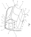
- Fig. 1 illustrates the broken-off cut rear region of a passenger car.
- the figure illustrates a view of the right inner side, which is a mirror image of the unillustrated left inner side.
- the presentation is simplified.
- body structures such as stiffening and fastening means are not shown because their representation is not required for the understanding of the invention.
- the representation of the body is schematic and does not recognize the existing cavities there.
- the illustrated body section 1 has a roof 2, from the side of a B-pillar 3 leads down to a bottom group, not shown.
- the corresponding B-pillar would be on the broken side of the vehicle to think.
- the B-pillars are inclined so that their upper end is shifted to the rear of the vehicle.
- the roof 2 goes over at its trailing edge in a rear window. Laterally, the rear window ends at a C-pillar 5, which is located at a distance from the B-pillar 3.
- the C-pillar 5 carries an inner lining 6.
- a rear right side door 7 is hinged to the B pillar in a known manner.
- a rear seat 8 At the height of the rear right side door 7 is a rear seat 8, to which a seat 9 and a rear seat back 11 belong.
- the rear seat 9 is located on a base surface 12, which belongs to a floor group and are formed in front of the foot wells 13.
- a rear shelf 15 extends to the lower edge of the rear window. 4
- the rear right side door 7 is provided in the usual manner for sedans with a side window 15.
- the side window 15 is divided by an approximately vertically extending strut 16 into a substantially quadrangular window field 17 and an approximately triangular window field 18.
- At the bottom of the two fields 17 and 18 are limited by a window sill 19.
- the window sill 19 extends at an angle smaller than 90 ° to a front edge of the window 20th
- the present in the window panel 17 disc is to move in a known manner up and down, to which it is guided, inter alia, in the vertical strut 16 in a known manner.
- the window panel 17 is selectively shaded by an associated roller blind 21, which can be pulled out of the interior of the door 7 through a slot in the window sill 19.
- the drive mechanism for the roller blind 21 is located in the interior of the door 7 below the window sill 19th
- Fig. 2 shows the essential components which are intended to drive the blind sheet 21 to lead or keep in the unused condition.
- the roller blind 21 has a blank which corresponds approximately to the surface of the window panel 17 and is approximated by substantially straight edges.
- the roller blind 21 is attached with its lower edge to a winding shaft 22 which is rotatably and axially movable between winding shaft bearing assemblies 23 and 24.
- the edge of the roller blind 21 remote from the winding shaft 22 forms a tubular loop 25 through which a tension rod arrangement passes.
- a tension rod arrangement passes.
- the guide arm 26 carries end a guide body 28th
- Each guide rail 29 includes a longitudinally extending groove chamber 30, which opens via a slot slot 31 in the direction of the roller blind 21 and is circular in cross section ,
- Each thrust member 32 consists of a cylindrical core 33 around which helically a raised coil 34 rotates.
- the helix 34 forms a helical tooth running around the core 33.
- the thrust member 32 thus has the shape of a helical flexible rack with a circular cross section.
- the thrust members 32 are only very little kink-resistant, so they are guided ausknickêt in the groove chamber 30.
- a guide tube 35 connects, which connects the groove chamber 30 of the respective guide rail 29 with a geared motor 36.
- To the gear motor 36 includes a permanent-magnet DC motor 37, which drives a transmission which is located in a transmission housing 38.
- On an output shaft 39 sits an output gear 40, which is designed so that it can positively engage in the toothing of the two push members 32. So that the thrust members 32 can not escape laterally, they are guided in holes 41 which run tangentially past the output gear 40. At these holes 41 close the guide tubes 35.
- still storage tubes may be present to guide the non-active part of the thrust member ordered.
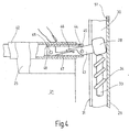
- FIG. 3 and 4 show, based on Fig. 2, the right end of the tension rod assembly, together with a section of the roller blind 21.
- the explanation given in connection with Fig. 4 applies mutatis mutandis to the other end of the tension rod assembly and the existing there interaction with the guide rail 29 on the left side.
- the guide body 28 has a shape that is adapted in cross section to the cross section of the groove chamber 30. It has an extension in the longitudinal direction the guide rail 29 seen on, which is only slightly larger than the diameter of the groove chamber 30. It can thereby be achieved that the guide body easily passes through the groove chamber 30, when its longitudinal axis, that is, the axis lying in the direction of movement, is oriented parallel to the axis of the groove chamber 30. The easy running in the guide chamber 30 is prevented, however, when the guide body 28 is slightly inclined in the groove chamber 30. There occurs a clamping effect, as it is well known from drawers or drawers. In this way, the guide body 28 may act as a braking member that the feed force of the drive member 32 introduces into the guide rail 29.
- the guide body 28 is connected to the guide arm 26 via a connecting arm 43 which leads out of the guide rail 29 through the guide slot 31.
- the connecting arm 43 protrudes into the guide arm 26 and is connected thereto via a hinge pin 44.
- the hinge pin 44 allows the guide arm 43 to pivot with respect to a pivot axis that is perpendicular to the plane of the drawing.
- the drawing level corresponds the clamping plane of the roller blind 21 in the region of the bow 42nd
- the bow 42 is provided at the height of the hinge axis 44 at the leading edge with a groove 45.
- a leaf spring 47 is provided which is for example a plastic spring and which starts in one piece from a holding block 48 which is riveted at 49 to the guide arm 43.
- the loop 25 is immediately adjacent to the winding shaft 22, that is, it is retracted below the parapet 19 of the side window 17.
- the user wants to span the roller blind 21 in front of the window 17 starting from this position, he sets the geared motor 36 in motion.
- the two push members 32 are advanced synchronously into the associated guide rails 29. They press on both sides of the roller blind 21, the guide body 28 upwards, ie they push them in front of him.
- a spring motor 50 as indicated schematically in Fig. 2.
- the force of the spring motor 50 is constantly striving to wind the roller blind 21 on the winding shaft 22 ie withdraw or hold.
- the force of the leaf spring 47 creates such a holding torque on the extension 46 of the connecting arm 43 that the guide body 28 remains in a position in which it can easily slide through the groove chamber 30, although the thrust members 32 generate torque on the guide body 28 wants to turn the connecting arm counterclockwise.
- the braking effect is effected by frictional engagement.
- the groove chamber 30 on the groove slot 31 opposite side with a Geradrändelung, whereby on the groove slot 31 opposite side a plurality of small, strip-shaped teeth formed which are aligned transversely to the longitudinal direction of the guide rail 29 and the length thereof approximately corresponds to the width of the groove slot 31.
- a toothing is shown schematically at 51 in FIG. It is not difficult to provide on the guide body 28 at that point a complementary toothing 51, which faces the toothing 51 of the groove chamber 30. Upon tilting of the guide body 28 in the manner described above, the teeth 51 would interlock with each other, so that a positive braking effect, i. a blockage comes about.
- Fig. 5 shows an embodiment with a separate braking member 52 which is movable relative to the guide body 28.
- a separate braking member 52 which is movable relative to the guide body 28.
- the guide body 28 is rigidly and immovably attached to the connecting arm 43. It has a cylindrical shape, which merges at both ends in truncated cones 52 and 53.
- the connecting arm 43 is rigid and immovable connected to the guide arm 26 and this longitudinally displaceable only in the bow 43.
- the guide body 28 is oriented to easily pass through the guide chamber 30.
- a through hole 54 which serves for the slidable receiving a rod 55 of the brake member 52.
- the rod 55 carries at both ends cylindrical heads 56 and 57.
- a spring arm 58 which is provided at its free end with a nose 59.
- a spring arm 61 is also present, which carries a nose 62 at its free end.
- the groove slot 31 opposite the rear wall of the groove chamber 30 contains, distributed equidistantly, small recesses 63 in the nose 59 and 61 can engage.
- the drive member 32 With the head 56, the drive member 32 is tension and pressure-resistant connected. Thus, both a in Fig. 5 upward force and a downwardly acting force can be transmitted to the brake member 52.
- the upward force corresponds to the extension of the roller blind, while the downward force is effective when retracting the roller blind 21.
- the downward or pulling force supports the action of the spring motor 50 and overcomes the sliding friction forces of the guide body 28 and the brake member 52 in the associated guide rail 29th
- the driving force of the drive member 32 is transmitted through the inclined surfaces of the spring arms 58, 61 and the guide body 28.
- Fig. 6 illustrates the situation when the force is not applied to the front edge and hinders deployment, but when, for example, when retracting an object between the guide arm 26 and the window sill 19 pinched.
- the upper spring arm 61 is urged outwardly in the manner previously explained, namely due to the action of the truncated cone 53.
- the nose 62 penetrates into one of the recesses 63 and blocks further retraction of the leading edge or Guide arm 26. This eliminates a shear injury.
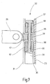
- Fig. 7 shows an embodiment in which the brake member 52 is formed partially elastomeric.
- the arrangement is similar to the arrangement of Fig. 5.
- the guide body 28 is provided with flat surfaces 65 and 66 which point in the direction of movement.
- FIGS. 4 or 6 If one of the situations according to FIGS. 4 or 6 appears, depending on the direction of movement, one of the two elastomer bodies 67 and 68 is clamped and compressed between the guide body 28 and the adjacent head 56 or 57. As a result, the relevant elastomeric body 67 or 68 is compressed and, as shown in FIG. 8, pressed against the inner wall of the groove chamber 30. Thereby, at least a part of the driving force, which originates from the drive member 32, introduced into the guide rail 29, before marriage dangerous injuries may occur.
- Fig. 8 shows the situation during extension. When entering a similar situation occurs, with the difference that not the elastomeric body 67 but the elastomeric body 68 is compressed.
- FIGS. 5 and 7 are bidirectional, while FIG. 3 shows an arrangement which is effective only during extension. The retraction need not be protected, because when retracting in the embodiment of FIG. 3, the loose abutment of the drive member 32 can submerge at any time without generating an additional force.
- the embodiments of FIGS. 5 and 7 may also be made non-directional by omitting the upper spring arm 61 in the embodiments of FIG. 5 and merely biasing the drive member 32 against the lower head 56 instead to be connected to this tensile and pressure resistant.
- the upper elastomer body 68 may also be omitted, although here the drive member 32 instead of tensile and pressure resistant to be connected to the lower head of the brake member 52 to be only pressure-resistant.
- a braking device is provided per guide rail, which ensures that at least a part of the driving force required for moving the window blind is introduced into the guide rail when the moving front edge of the window blinds abuts against an obstacle.
Landscapes
- Engineering & Computer Science (AREA)
- Mechanical Engineering (AREA)
- Operating, Guiding And Securing Of Roll- Type Closing Members (AREA)
Applications Claiming Priority (2)
| Application Number | Priority Date | Filing Date | Title |
|---|---|---|---|
| DE102005018903 | 2005-04-21 | ||
| DE102005029560A DE102005029560A1 (de) | 2005-04-21 | 2005-06-23 | Rollo mit Einklemmschutz |
Publications (2)
| Publication Number | Publication Date |
|---|---|
| EP1714813A2 true EP1714813A2 (fr) | 2006-10-25 |
| EP1714813A3 EP1714813A3 (fr) | 2009-12-02 |
Family
ID=36699082
Family Applications (1)
| Application Number | Title | Priority Date | Filing Date |
|---|---|---|---|
| EP06001172A Withdrawn EP1714813A3 (fr) | 2005-04-21 | 2006-01-20 | Store enroulable avec dispositif anti-coincement |
Country Status (6)
| Country | Link |
|---|---|
| US (1) | US20060237152A1 (fr) |
| EP (1) | EP1714813A3 (fr) |
| JP (1) | JP2006298370A (fr) |
| KR (1) | KR20060110815A (fr) |
| CN (1) | CN1854452B (fr) |
| DE (1) | DE102005029560A1 (fr) |
Cited By (1)
| Publication number | Priority date | Publication date | Assignee | Title |
|---|---|---|---|---|
| EP2017107A1 (fr) * | 2007-07-20 | 2009-01-21 | BOS GmbH & Co. KG | Store pour ombrager doté d'un verrouillage |
Families Citing this family (12)
| Publication number | Priority date | Publication date | Assignee | Title |
|---|---|---|---|---|
| DE102005029559B4 (de) * | 2005-06-23 | 2007-05-03 | Bos Gmbh & Co. Kg | Heckfensterrollo mit vollständiger Schlitzabdeckung durch das Auszugsprofil |
| ITTV20080004A1 (it) * | 2008-01-10 | 2009-07-11 | Nice Spa | Azionamento per avvolgibili con protezione contro vento eccessivo |
| JP2011131807A (ja) * | 2009-12-25 | 2011-07-07 | Toyota Boshoku Corp | サンシェード装置 |
| CN102381159A (zh) * | 2010-09-03 | 2012-03-21 | 皇田工业股份有限公司 | 遮阳帘用的挂钩 |
| JP6000563B2 (ja) * | 2012-02-09 | 2016-09-28 | 芦森工業株式会社 | 車両用ウインドウシェード装置 |
| US8540008B2 (en) * | 2012-02-14 | 2013-09-24 | Ing-Wen Chen | Lift guiding system for a car curtain |
| US9278610B2 (en) * | 2014-06-13 | 2016-03-08 | Ford Global Technologies, Llc | Vehicle anti-pinch moonroof control system and method |
| RU185222U1 (ru) * | 2017-02-13 | 2018-11-26 | Общество с ограниченной ответственностью "Цифровая динамика" | Устройство управления положением подвижной части автомобиля |
| CN109532684A (zh) * | 2018-11-22 | 2019-03-29 | 大乘汽车有限公司 | 一种遮物帘 |
| CN109552186A (zh) * | 2018-11-22 | 2019-04-02 | 大乘汽车有限公司 | 一种车用遮物帘 |
| CN115320342B (zh) * | 2022-07-19 | 2025-08-05 | 宁波精成车业有限公司 | 一种用于汽车后座侧帘的电动卷帘驱动装置 |
| CN117067876A (zh) * | 2023-07-31 | 2023-11-17 | 浙江吉利控股集团有限公司 | 遮阳帘结构及车辆 |
Family Cites Families (7)
| Publication number | Priority date | Publication date | Assignee | Title |
|---|---|---|---|---|
| US315789A (en) * | 1885-04-14 | Curtain-fixture | ||
| US529517A (en) * | 1894-11-20 | Holding device for spring-actuated shades | ||
| WO1987003035A1 (fr) * | 1985-11-06 | 1987-05-21 | Automatic Roller Doors Australia Pty Ltd | Barre de securite pour porte |
| DE10057762A1 (de) * | 2000-11-22 | 2002-06-06 | Bos Gmbh | Fensterrollo mit Ausgleich gegen Verzug |
| DE10057759A1 (de) * | 2000-11-22 | 2002-06-06 | Bos Gmbh | Fensterscheibe mit daran befestigtem Fensterrollo |
| DE10245929A1 (de) * | 2002-09-30 | 2004-04-08 | Arvinmeritor Gmbh | Baugruppe bestehend aus mindestens einer Führungsschiene und einem Schlitten, insbesondere für ein Sonnenschutzrollo in einem Kraftfahrzeug |
| DE10248958A1 (de) * | 2002-10-21 | 2004-04-29 | Arvinmeritor Gmbh | Baugruppe bestehend aus mindestens einer Führungsschiene und einem Schlitten, insbesondere für ein Sonnenschutzrollo in einem Kraftfahrzeug |
-
2005
- 2005-06-23 DE DE102005029560A patent/DE102005029560A1/de not_active Ceased
-
2006
- 2006-01-20 EP EP06001172A patent/EP1714813A3/fr not_active Withdrawn
- 2006-04-19 JP JP2006115621A patent/JP2006298370A/ja active Pending
- 2006-04-20 KR KR1020060035652A patent/KR20060110815A/ko not_active Withdrawn
- 2006-04-20 CN CN2006100755420A patent/CN1854452B/zh not_active Expired - Fee Related
- 2006-04-20 US US11/407,581 patent/US20060237152A1/en not_active Abandoned
Cited By (1)
| Publication number | Priority date | Publication date | Assignee | Title |
|---|---|---|---|---|
| EP2017107A1 (fr) * | 2007-07-20 | 2009-01-21 | BOS GmbH & Co. KG | Store pour ombrager doté d'un verrouillage |
Also Published As
| Publication number | Publication date |
|---|---|
| CN1854452B (zh) | 2012-08-01 |
| EP1714813A3 (fr) | 2009-12-02 |
| JP2006298370A (ja) | 2006-11-02 |
| KR20060110815A (ko) | 2006-10-25 |
| US20060237152A1 (en) | 2006-10-26 |
| CN1854452A (zh) | 2006-11-01 |
| DE102005029560A1 (de) | 2006-11-02 |
Similar Documents
| Publication | Publication Date | Title |
|---|---|---|
| EP1468854B1 (fr) | Store à enrouleur pour vitres latérales | |
| EP2039547B1 (fr) | Store de fenêtre latérale doté d'une aide à l'introduction | |
| EP1859976B1 (fr) | Volet roulant avec entraînement silencieux par ressort en spirale | |
| DE10228028B3 (de) | Heckscheibenrollo mit Hubkassette | |
| DE102007063705B4 (de) | Rollo mit Lochbandantrieb | |
| DE102005029559B4 (de) | Heckfensterrollo mit vollständiger Schlitzabdeckung durch das Auszugsprofil | |
| EP1942022B1 (fr) | Store doté d'un centrage par butées | |
| DE112012002485B4 (de) | Sonnenschutzvorrichtung | |
| EP2060421B1 (fr) | Agencement de store doté d'un entraînement à friction réduite | |
| EP1149718A2 (fr) | Store pour fenêtre latérale avec obturateur de fente | |
| DE10005951A1 (de) | Heckfensterrollo | |
| EP1609647A2 (fr) | Store à enrouler avec couvercle sur la fente extracte | |
| EP1932700A2 (fr) | Store de fenêtre triangulaire pour véhicules automobiles | |
| EP1533158A2 (fr) | Store à enrouleur pour vitres latérales | |
| EP1619057B1 (fr) | Agencement de store pare-soleil pour vitre latérale | |
| EP1300270B1 (fr) | Rideau de lamelles et lamelle correspondante | |
| EP1800922B1 (fr) | Store à enrouler pour ombrage total d'une vitre arrière | |
| DE102005029560A1 (de) | Rollo mit Einklemmschutz | |
| EP1724137B1 (fr) | Store à enroulement pour fenêtre avec rouleau axialement réglable | |
| EP1398190B1 (fr) | Dispositif pare-soleil à store enrouleur pour une fenêtre d'automobile | |
| DE102005032043B4 (de) | Rollovorrichtung für ein Kraftfahrzeug | |
| EP1739275A2 (fr) | Volet roulant avec dispositif anti-pincement éléctronique | |
| EP1738942B1 (fr) | Store à enrouleur pour véhicule automobile muni d'une butée de contact fixée rigidement sur un actionneur | |
| DE202005020611U1 (de) | Rollo mit Einklemmschutz | |
| DE202005020693U1 (de) | Rollo mit elektrischem Einklemmschutz |
Legal Events
| Date | Code | Title | Description |
|---|---|---|---|
| PUAI | Public reference made under article 153(3) epc to a published international application that has entered the european phase |
Free format text: ORIGINAL CODE: 0009012 |
|
| AK | Designated contracting states |
Kind code of ref document: A2 Designated state(s): AT BE BG CH CY CZ DE DK EE ES FI FR GB GR HU IE IS IT LI LT LU LV MC NL PL PT RO SE SI SK TR |
|
| AX | Request for extension of the european patent |
Extension state: AL BA HR MK YU |
|
| PUAL | Search report despatched |
Free format text: ORIGINAL CODE: 0009013 |
|
| AK | Designated contracting states |
Kind code of ref document: A3 Designated state(s): AT BE BG CH CY CZ DE DK EE ES FI FR GB GR HU IE IS IT LI LT LU LV MC NL PL PT RO SE SI SK TR |
|
| AX | Request for extension of the european patent |
Extension state: AL BA HR MK YU |
|
| RIC1 | Information provided on ipc code assigned before grant |
Ipc: E06B 7/36 20060101ALI20091028BHEP Ipc: B60R 5/04 20060101ALI20091028BHEP Ipc: B60J 1/20 20060101AFI20060803BHEP |
|
| 17P | Request for examination filed |
Effective date: 20100116 |
|
| AKX | Designation fees paid |
Designated state(s): DE FR SE |
|
| GRAP | Despatch of communication of intention to grant a patent |
Free format text: ORIGINAL CODE: EPIDOSNIGR1 |
|
| INTG | Intention to grant announced |
Effective date: 20130726 |
|
| STAA | Information on the status of an ep patent application or granted ep patent |
Free format text: STATUS: THE APPLICATION IS DEEMED TO BE WITHDRAWN |
|
| 18D | Application deemed to be withdrawn |
Effective date: 20131206 |