EP2017410A2 - Elektronischer Sperrmechanismus - Google Patents
Elektronischer Sperrmechanismus Download PDFInfo
- Publication number
- EP2017410A2 EP2017410A2 EP08158383A EP08158383A EP2017410A2 EP 2017410 A2 EP2017410 A2 EP 2017410A2 EP 08158383 A EP08158383 A EP 08158383A EP 08158383 A EP08158383 A EP 08158383A EP 2017410 A2 EP2017410 A2 EP 2017410A2
- Authority
- EP
- European Patent Office
- Prior art keywords
- piezo
- locking mechanism
- mechanism according
- film
- pusher
- Prior art date
- Legal status (The legal status is an assumption and is not a legal conclusion. Google has not performed a legal analysis and makes no representation as to the accuracy of the status listed.)
- Granted
Links
- 230000007246 mechanism Effects 0.000 title claims abstract description 39
- 230000000903 blocking effect Effects 0.000 title claims description 6
- 230000004913 activation Effects 0.000 claims abstract description 49
- 230000003213 activating effect Effects 0.000 claims abstract description 7
- 239000011888 foil Substances 0.000 claims abstract description 7
- 239000000463 material Substances 0.000 claims description 15
- 239000002985 plastic film Substances 0.000 claims description 12
- 229920006255 plastic film Polymers 0.000 claims description 12
- 239000004033 plastic Substances 0.000 claims description 3
- 238000003780 insertion Methods 0.000 description 7
- 230000037431 insertion Effects 0.000 description 7
- 238000009434 installation Methods 0.000 description 3
- 230000008878 coupling Effects 0.000 description 2
- 238000010168 coupling process Methods 0.000 description 2
- 238000005859 coupling reaction Methods 0.000 description 2
- 238000001514 detection method Methods 0.000 description 2
- 235000014676 Phragmites communis Nutrition 0.000 description 1
- 229910000639 Spring steel Inorganic materials 0.000 description 1
- 238000013475 authorization Methods 0.000 description 1
- 238000011109 contamination Methods 0.000 description 1
- 230000007797 corrosion Effects 0.000 description 1
- 238000005260 corrosion Methods 0.000 description 1
- 230000000694 effects Effects 0.000 description 1
- 238000009429 electrical wiring Methods 0.000 description 1
- 238000005538 encapsulation Methods 0.000 description 1
- 239000007789 gas Substances 0.000 description 1
- 239000002184 metal Substances 0.000 description 1
Images

Classifications
-
- E—FIXED CONSTRUCTIONS
- E05—LOCKS; KEYS; WINDOW OR DOOR FITTINGS; SAFES
- E05B—LOCKS; ACCESSORIES THEREFOR; HANDCUFFS
- E05B47/00—Operating or controlling locks or other fastening devices by electric or magnetic means
- E05B47/06—Controlling mechanically-operated bolts by electro-magnetically-operated detents
- E05B47/0611—Cylinder locks with electromagnetic control
- E05B47/0619—Cylinder locks with electromagnetic control by blocking the rotor
- E05B47/0626—Cylinder locks with electromagnetic control by blocking the rotor radially
- E05B47/063—Cylinder locks with electromagnetic control by blocking the rotor radially with a rectilinearly moveable blocking element
-
- E—FIXED CONSTRUCTIONS
- E05—LOCKS; KEYS; WINDOW OR DOOR FITTINGS; SAFES
- E05B—LOCKS; ACCESSORIES THEREFOR; HANDCUFFS
- E05B47/00—Operating or controlling locks or other fastening devices by electric or magnetic means
- E05B47/0001—Operating or controlling locks or other fastening devices by electric or magnetic means with electric actuators; Constructional features thereof
- E05B47/0011—Operating or controlling locks or other fastening devices by electric or magnetic means with electric actuators; Constructional features thereof with piezoelectric actuators
-
- E—FIXED CONSTRUCTIONS
- E05—LOCKS; KEYS; WINDOW OR DOOR FITTINGS; SAFES
- E05B—LOCKS; ACCESSORIES THEREFOR; HANDCUFFS
- E05B47/00—Operating or controlling locks or other fastening devices by electric or magnetic means
- E05B47/06—Controlling mechanically-operated bolts by electro-magnetically-operated detents
- E05B47/0611—Cylinder locks with electromagnetic control
- E05B47/0615—Cylinder locks with electromagnetic control operated by handles, e.g. by knobs
-
- E—FIXED CONSTRUCTIONS
- E05—LOCKS; KEYS; WINDOW OR DOOR FITTINGS; SAFES
- E05B—LOCKS; ACCESSORIES THEREFOR; HANDCUFFS
- E05B47/00—Operating or controlling locks or other fastening devices by electric or magnetic means
- E05B47/0001—Operating or controlling locks or other fastening devices by electric or magnetic means with electric actuators; Constructional features thereof
- E05B47/0002—Operating or controlling locks or other fastening devices by electric or magnetic means with electric actuators; Constructional features thereof with electromagnets
Definitions
- the invention relates to an electronic locking mechanism, in particular for a lock cylinder of a mortise lock, with a locking device having an electrically controllable actuator, with a control device for controlling the actuator and with an activation device for activating the control device.
- Such electronic locking mechanisms are often used in locking systems with an electronic lock cylinder.
- the locking device is designed for selectively blocking or releasing a core movably arranged in a housing or for selectively producing or solving a positive connection between a core or a knob and a locking cam of the lock cylinder.
- These lock cylinders are often equipped with its own power storage, such as a battery to avoid a consuming to be laid electrical wiring.
- Today's electronic locking mechanisms are controlled for example by means of a numerical code, a person recognition device or a receiving device for receiving signals of a portable transponder or electronic key.
- the activation device is provided which generates an activation pulse immediately before the intended activation of the control device, which activates the control device.
- the activation device In the simplest case, this is an electromechanical switch which, when an electronic key is inserted into a closing channel, connects the control device to the current memory.
- Such switches have a high installation cost and are prone to contamination and corrosion.
- the EP 1 531 431 A3 discloses an electronically activatable locking mechanism.
- a signal detection device activates a data acquisition device only after receiving a signal of a transponder. This arrangement has a particularly low power consumption. However, the power storage is constantly loaded by the signal detection means.
- the invention is based on the problem to make an electronic locking mechanism of the type mentioned so that it is particularly easy to use and very inexpensive to produce.
- the activation device has an elastically deformable piezo film that the piezo film formed as a component manufactured independently of the locking device is and is arranged such that it is deformable in an opening operation of the locking mechanism for generating an activation pulse for the control device.
- the piezo film is designed as a component manufactured independently of the blocking device, the actuator can be arranged as safe as possible inside the locking mechanism according to the invention, while the piezo film is arranged such that it is deformed directly at the beginning of the opening movement and thus early generates the activation pulse. As a result, the locking mechanism according to the invention can be actuated particularly comfortably.
- the opening operation may be, for example, the insertion of a key carrying a transponder into a lock channel of a lock cylinder, drawing a card with a transponder through a slot of a card reader or an initial movement of the core, or gripping a knob of a lock cylinder designed as a knob cylinder.
- the locking mechanism according to the invention is particularly versatile. Since the piezo film generates a signal directly through the deformation, the activation device can be produced particularly cost-effectively and has particularly small dimensions. The power requirement of the activation device is also kept very low thanks to the invention.
- the activation device is structurally particularly simple if the piezo film has a preformed or tensioned plastic film and if a layer of a piezo material is applied to the plastic film is applied.
- Another advantage of this design is that the piezo film thereby has only a very small footprint. As a result, the electronic locking mechanism is particularly compact.
- Temperature fluctuations, vibrations and the like can generate voltages in piezo foils.
- the generation of an activation pulse by temperature fluctuations or vibrations can be avoided if the plastic film has two layers of piezo material arranged next to one another and electrically separated from one another and if the activation pulse can be determined from a difference between generated stresses of the layers.
- the determination of the difference between the two signals of the layers can be determined, for example, by means of a passive operation circuit, to the inputs of which one of the layers is connected in each case. Only when a difference in the voltages of the layers of piezo material is applied to two inputs of the passive operation circuit, the operation circuit is able to pass the activation pulse to the control device. Thanks to the invention can be compensated by the layout of the plastic film, the temperature fluctuations.
- the invention contributes, if only one of the adjacent layers of piezo material is deformable during the opening operation and / or if the layers are differently polarized.
- the piezo film could for example protrude directly into a closing channel, into a slot of a card reader or a recess in the core of the lock cylinder and be deformed directly during the opening operation.
- wear of the piezo film can be kept particularly low if the activation device has a pusher and if the pusher rests with one end on the piezo film or faces it and can be deflected by the opening operation.
- This design makes it possible to ensure a precisely defined deformation of the piezo film during the opening movement. This defined deformation also ensures that the activation pulse neither exceeds nor falls short of intended limits.
- Damage to the layer of piezoelectric material during operation of the locking mechanism according to the invention can be easily avoided if the layer of piezoelectric material is arranged on the side facing away from the pusher of the plastic film. Furthermore, this makes it possible to protect the layer of the piezoelectric material particularly reliably against corrosive gases, temperature fluctuations and the effects of moisture.
- a tolerance compensation in the deformation of the piezo film could be made possible for example by a corresponding elasticity of the piezo film.
- it contributes, according to another advantageous embodiment of the invention, when the pusher between the piezo film and a movable in the opening operation component is designed elastically yielding.
- the elastically yielding design for example, by a resilient design of the Pusher, for example, be produced from spring steel or by a multi-part design of the pusher with a spring element.
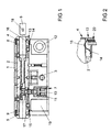
- FIG. 1 shows a double-profile lock cylinder with a housing 1 and a rotatably disposed in the housing 1 core 2.
- the core 2 has in its central region a cam 3 and at its ends in each case a closing channel 4, 5 for introducing a key 6 shown schematically
- Lock cylinder has an electronic locking mechanism with each near the front sides of the housing 1 arranged code receivers 8, 9 and with a locking device 7.
- the locking device 7 has a controllable by an electromagnet 10 locking bolt 11 as an actuator for selectively blocking or releasing the movement of the core.
- the locking mechanism on a power storage 12 with a battery.
- the electronic locking mechanism has an activation device 13, each with a, at each beginning of the closing channels 4, 5 arranged piezo foil 14, 15.
- a piezo film 14, 15 opposite pushers 16, 17 projects into the respective closing channel 4, 5 into it.
- the activation device 13 generates an activation pulse upon insertion of the key 6 into the respective closing channel 4, 5 for activating a control device 19.
- the code receiver 8, 9 detect signals from transponders 18 of the key 6 and forward them to the control device 19.
- the control device 19 determines the signals of the transponder 18, whether the key 6 is authorized to unlock the lock cylinder. In the presence of an authorization controls the control device 19, the locking device 7 and holds the locking bar 11 in a movement of the core 2 releasing position.
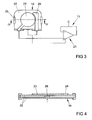
- FIG. 2 shows greatly enlarged part of the activation device 13 from FIG. 1 , It can be seen that the pusher 16 is formed as a bent metal strip and has a latching connection 20 in the core 2. With an elastically yielding arc, the pusher 16 projects into the closing channel 4. The free end of the pusher 16 is opposite to the piezo film 14 with a small distance. When inserting the key 6 into the closing channel 4, the pusher 16 presses on the piezo film 14 and deforms it. In this case, the described activation pulse is generated. The shape and the elasticity of the pusher 16 compensates for tolerances with respect to the closing channel 4 and prevents overloading of the piezo film 14.
- FIG. 3 shows a plan view of the piezo film 14 with an operation circuit 21 of the activation device 13.
- the piezo film 14 has a plastic film 22 with two juxtaposed layers 23, 24 of piezo material. Only one of the layers 23 of piezo material is in the range of motion in the Figures 1 and 2
- the other layer 24 of piezoelectric material serves as a comparison layer and allows compensation of temperature and other influences by means of the operation circuit 21.
- the activation pulse is generated by the operation circuit 21 only when generated by means of the layers 23, 24 of piezoelectric material different signals become.
- the plastic film 22 is partially encapsulated by plastic 25. The encapsulation allows easy installation of the piezo film 14 in the lock cylinder.
- FIG. 4 shows a sectional view through the piezo film 14 FIG. 3 , It can be seen here that the piezo film 14 has a total of two plastic films 22, between which a mass element 26 is arranged. The ground element 26 is also connected to the operational circuit 21 off FIG. 3 connected. The actuating direction of the piezo film 14 is indicated by an arrow.
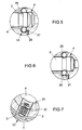
- FIG. 5 shows a sectional view through a further embodiment of the activation device 13, in which a pusher 27 is formed as a ball and rests on a piezoelectric film 28.
- a pusher 27 is formed as a ball and rests on a piezoelectric film 28.
- the pusher 27 is pressed by the tip of the key 6 against the piezoelectric film 28, whereupon it deforms.
- the pusher 27 snaps into a recess 29 of the key 6, whereby the piezo film 28 is stretched smooth by its inherent elasticity.
- the pusher 27 also holds the key 6 in its fully inserted into the closing channel 4 position.
- FIG. 7 shows a further embodiment of the activation device 13, in which a pusher 30 is designed in two parts and protrudes with one end into the closing channel 4 and rests with the other end on a preformed piezo film 31. Between the ends of the pusher 30, a spring element 32 is arranged. The spring element 32 compensates tolerances and prevents overloading of the piezo film 31. Upon insertion of the key 6 in the closing channel 4, the piezo film 31 is also deformed and generates the activation pulse.
- FIG. 8 shows a designed as a knob cylinder lock cylinder, in which a schematically illustrated locking direction 33 has an actuator, not shown for selectively releasing or generating a positive connection between a core 34 and a knob 35 has.
- the activation device 13 for generating an activation pulse for the likewise schematically illustrated Control device 19 for controlling the blocking device 33 has a pusher 36 connected to the core 34.
- the pusher 36 is biased by a spring member 37 in a series of arranged in the knob 35 recesses 38.
- the spring element 37 is supported on a piezo film 39 of the activation device 13.
- the pusher 36 Upon an initial rotation of the knob 35, the pusher 36 is moved by the depressions 38 in the knob 35 and the piezo film 39 is deformed, whereby an activation pulse for the control device 19 is generated.
- the piezo film can also directly on the outside of the knob of the lock cylinder FIG. 8 be arranged and deformed by the gripping of the knob.
Landscapes
- Physics & Mathematics (AREA)
- Electromagnetism (AREA)
- Lock And Its Accessories (AREA)
- General Electrical Machinery Utilizing Piezoelectricity, Electrostriction Or Magnetostriction (AREA)
- Electrically Driven Valve-Operating Means (AREA)
Abstract
Description
- Die Erfindung betrifft einen elektronischen Sperrmechanismus, insbesondere für einen Schließzylinder eines Einsteckschlosses, mit einer einen elektrisch ansteuerbaren Aktor aufweisenden Sperreinrichtung, mit einer Steuereinrichtung zur Ansteuerung des Aktors und mit einer Aktivierungseinrichtung zur Aktivierung der Steuereinrichtung.
- Solche elektronischen Sperrmechanismen werden häufig bei Schließanlagen mit einem elektronischen Schließzylinder eingesetzt. Die Sperreinrichtung ist zum wahlweisen Blockieren oder Freigeben eines in einem Gehäuse beweglich angeordneten Kerns oder zur wahlweisen Erzeugung oder Lösung eines Formschlusses zwischen einem Kern oder einem Knauf und einem Schließbart des Schließzylinders ausgebildet. Diese Schließzylinder sind zur Vermeidung einer aufwändig zu verlegenden elektrischen Verkabelung häufig mit einem eigenen Stromspeicher, wie einer Batterie ausgestattet. Angesteuert werden heutige elektronische Sperrmechanismen beispielsweise mittels eines Zahlencodes, einer Personenerkennungseinrichtung oder einer Empfangseinrichtung zum Empfang von Signalen eines tragbaren Transponders oder elektronischen Schlüssels. Um den Stromverbrauch des elektronischen Sperrmechanismus möglichst gering zu halten, ist die Aktivierungseinrichtung vorgesehen, welche unmittelbar vor der vorgesehenen Ansteuerung der Steuereinrichtung einen Aktivierungsimpuls erzeugt, welcher die Steuereinrichtung aktiviert. Die Aktivierungseinrichtung ist im einfachsten Fall ein elektromechanischer Schalter, welcher beim Einführen eines elektronischen Schlüssels in einen Schließkanal die Steuereinrichtung mit dem Stromspeicher verbindet. Solche Schalter weisen jedoch einen hohen Montageaufwand auf und sind anfällig gegenüber Verschmutzung und Korrosion.
- Aus der
EP 1 148 189 B1 ist ein elektronischer Sperrmechanismus der eingangs genannten Art bekannt geworden, bei der der Aktor elektromagnetisch gestaltet ist und bei einem Einführen eines elektronischen Schlüssels in den Schließkanal einen elektromagnetischen Aktivierungsimpuls für die Steuereinrichtung erzeugt. Nachteilig bei diesem elektronischen Sperrmechanismus ist die Koppelung der Erzeugung des Aktivierungsimpulses an dem Aktor. Aus Gründen der Sicherheit gegen eine unberechtigte Entriegelung sollte jedoch der Aktor im Inneren des Schließzylinders angeordnet sein. Dies führt jedoch dazu, dass die Aktivierung der Steuereinrichtung beim Einführen des Schlüssels jedoch erst zu einem späten Zeitpunkt erfolgt, so dass der elektronische Sperrmechanismus nach dem vollständigen Einführen des Schlüssels eine Zeitspanne benötigt, um die Bewegung des Kerns freizugeben. Diese Verzögerung der Freigabe des Schließzylinders wird jedoch häufig als sehr unkomfortabel wahrgenommen. Weiterhin erfordert diese Gestaltung einen sehr aufwändigen und damit kostenintensiven Elektromagneten. - Aus der
EP 1 380 714 A2 ist ein elektronischer Sperrmechanismus bekannt geworden, bei dem ein Piezobieger als Aktor ausgebildet ist. Bei einer Bewegung des Piezobiegers durch das Einführen des Schlüssels wird der Aktivierungsimpuls erzeugt. Nachteilig ist auch bei diesem Sperrmechanismus die Koppelung der Erzeugung des Aktivierungsimpulses an den Aktor, was zu einem unkomfortablen Schließen des Schließzylinders führen kann. Bei einem schnellen Einführen des Schlüssels besteht die Gefahr, dass der Aktivierungsimpuls zu stark wird. Daher erfordert dieser Sperrmechanismus aufwändige Mittel zur Begrenzung des Aktivierungsimpulses. - Aus der
DE 10 2004 004 246 A1 ist eine Aktivierung einer Steuerelektronik durch magnetische Schaltmittel, wie beispielsweise Permanentmagnete zur Ansteuerung von Hallsensoren bekannt. Solche Hallsensoren erfordern jedoch eine ständig aktive elektronische Schaltung mit einem entsprechend hohen Stromverbrauch. Passive Reed Relais sind mechanisch empfindlich und weisen einen hohen Bauraum auf. Ein Schlüssel zur Ansteuerung der Hallsensoren erfordert zudem einen sehr starken Permanentmagneten, was insbesondere bei mehreren mitzuführenden Schlüsseln unerwünscht ist. Weiterhin lassen sich solche Hallsensoren von Fremdmagnetfeldern ansteuern, was ebenfalls zu einem hohen Stromverbrauch führt. - Die
EP 1 531 431 A3 offenbart einen elektronisch aktivierbaren Sperrmechanismus. Eine Signalerfassungseinrichtung aktiviert eine Datenerfassungseinrichtung erst nach dem Empfang eines Signals eines Transponders. Diese Anordnung weist einen besonders geringen Strombedarf auf. Jedoch wird der Stromspeicher ständig durch die Signalerfassungseinrichtung belastet. - Der Erfindung liegt das Problem zugrunde, einen elektronischen Sperrmechanismus der eingangs genannten Art so zu gestalten, dass er besonders komfortabel bedienbar und besonders kostengünstig herstellbar ist.
- Dieses Problem wird erfindungsgemäß dadurch gelöst, dass die Aktivierungseinrichtung eine elastisch verformbare Piezofolie aufweist, dass die Piezofolie als unabhängig von der Sperreinrichtung gefertigtes Bauteil ausgebildet ist und derart angeordnet ist, dass sie bei einer Öffnungsbetätigung des Sperrmechanismus zur Erzeugung eines Aktivierungsimpulses für die Steuereinrichtung verformbar ist.
- Durch diese Gestaltung wird mit der Piezofolie ein besonders kompaktes Mittel zur Erzeugung des Aktivierungsimpulses eingesetzt. Da die Piezofolie als unabhängig von der Sperreinrichtung gefertigtes Bauteil ausgebildet ist, kann der Aktor manipulationssicher möglichst weit im Inneren des erfindungsgemäßen Sperrmechanismus angeordnet werden, während die Piezofolie derart angeordnet wird, dass sie direkt zu Beginn der Öffnungsbewegung verformt wird und damit frühzeitig den Aktivierungsimpuls erzeugt. Hierdurch lässt sich der erfindungsgemäße Sperrmechanismus besonders komfortabel betätigen. Die Öffnungsbetätigung kann beispielsweise die Einführung eines einen Transponder tragenden Schlüssels in einen Schließkanal eines Schließzylinders, das Durchziehen einer Karte mit einem Transponder durch einen Schlitz eines Kartenlesegerätes oder eine anfängliche Bewegung des Kerns oder ein Greifen eines Knaufes eines als Knaufzylinder ausgebildeten Schließzylinders sein. Damit ist der erfindungsgemäße Sperrmechanismus besonders vielseitig einsetzbar. Da die Piezofolie direkt durch die Verformung ein Signal erzeugt, lässt sich die Aktivierungseinrichtung besonders kostengünstig fertigen und weist besonders kleine Abmessungen auf. Der Strombedarf der Aktivierungseinrichtung wird dank der Erfindung ebenfalls besonders gering gehalten.
- Die Aktivierungseinrichtung gestaltet sich gemäß einer anderen vorteilhaften Weiterbildung der Erfindung konstruktiv besonders einfach, wenn die Piezofolie eine vorgeformte oder gespannte Kunststofffolie hat und wenn auf der Kunststofffolie eine Schicht aus einem Piezomaterial aufgebracht ist. Ein weiterer Vorteil dieser Gestaltung besteht darin, dass die Piezofolie hierdurch nur einen sehr geringen Platzbedarf aufweist. Hierdurch gestaltet sich der elektronische Sperrmechanismus besonders kompakt.
- Temperaturschwankungen, Erschütterungen und dergleichen können bei Piezofolien Spannungen erzeugen. Die Erzeugung eines Aktivierungsimpulses durch Temperaturschwankungen oder Erschütterungen lässt sich jedoch gemäß einer anderen vorteilhaften Weiterbildung der Erfindung vermeiden, wenn die Kunststofffolie zwei nebeneinander angeordnete und elektrisch voneinander getrennte Schichten aus Piezomaterial aufweist und wenn der Aktivierungsimpuls aus einer Differenz zwischen erzeugten Spannungen der Schichten ermittelbar ist. Die Ermittlung der Differenz der beiden Signale der Schichten kann beispielsweise mittels einer passiven Operationsschaltung ermittelt werden, an deren Eingängen jeweils eine der Schichten angeschlossen ist. Erst wenn an zwei Eingängen der passiven Operationsschaltung eine Differenz der Spannungen der Schichten aus Piezomaterial anliegt, vermag die Operationsschaltung den Aktivierungsimpuls an die Steuereinrichtung zu leiten. Dank der Erfindung lassen sich durch das Layout der Kunststofffolie die Temperaturschwankungen kompensieren.
- Zur weiteren Vereinfachung der Kompensation der Temperatureinflüsse trägt es gemäß einer anderen vorteilhaften Weiterbildung der Erfindung bei, wenn nur eine der nebeneinander angeordneten Schichten aus Piezomaterial bei der Öffnungsbetätigung verformbar ist und/oder wenn die Schichten unterschiedlich polarisiert sind.
- Zur Vereinfachung der Montage des erfindungsgemäßen Sperrmechanismus trägt es bei, wenn die Piezofolie mit Kunststoff teilweise umspritzt ist.
- Die Piezofolie könnte beispielsweise unmittelbar in einen Schließkanal, in einen Schlitz eines Kartenlesegerätes oder eine Vertiefung im Kern des Schließzylinders hineinragen und bei der Öffnungsbetätigung unmittelbar verformt werden. Ein Verschleiß der Piezofolie lässt sich jedoch gemäß einer anderen vorteilhaften Weiterbildung der Erfindung besonders gering halten, wenn die Aktivierungseinrichtung einen Drücker aufweist und wenn der Drücker mit einem Ende an der Piezofolie anliegt oder dieser gegenübersteht und von der Öffnungsbetätigung auslenkbar ist. Durch diese Gestaltung lässt sich eine genau definierte Verformung der Piezofolie bei der Öffnungsbewegung sicherstellen. Diese definierte Verformung stellt zudem sicher, dass der Aktivierungsimpuls vorgesehene Grenzen weder überschreitet noch unterschreitet.
- Eine Beschädigung der Schicht aus Piezomaterial im Betrieb des erfindungsgemäßen Sperrmechanismus lässt sich einfach vermeiden, wenn die Schicht aus Piezomaterial auf der dem Drücker abgewandten Seite der Kunststofffolie angeordnet ist. Weiterhin lässt sich hierdurch die Schicht aus dem Piezomaterial besonders zuverlässig vor korrosiven Gasen, Temperaturschwankungen und Feuchtigkeitseinflüssen schützen.
- Ein Toleranzausgleich bei der Verformung der Piezofolie könnte beispielsweise durch eine entsprechende Elastizität der Piezofolie ermöglicht werden. Zur Vereinfachung des Toleranzausgleichs und zur Erhöhung der Lebensdauer der Piezofolie trägt es jedoch gemäß einer anderen vorteilhaften Weiterbildung der Erfindung bei, wenn der Drücker zwischen der Piezofolie und einem bei der Öffnungsbetätigung beweglichen Bauteil elastisch nachgiebig gestaltet ist. Die elastisch nachgiebige Gestaltung kann beispielsweise durch eine federelastische Gestaltung des Drückers, beispielsweise aus Federblech erzeugt werden oder durch eine mehrteilige Gestaltung des Drückers mit einem Federelement.
- Die Erfindung lässt zahlreiche Ausführungsformen zu. Zur weiteren Verdeutlichung ihres Grundprinzips ist eine davon in der Zeichnung dargestellt und wird nachfolgend beschrieben. Diese zeigt in
- Fig. 1
- eine Schnittdarstellung durch einen Schließ- zylinder mit einem erfindungsgemäßen Sperrme- chanismus,
- Fig. 2
- stark vergrößert eine Darstellung einer Akti- vierungseinrichtung des erfindungsgemäßen Sperrmechanismus aus
Figur 1 , - Fig. 3
- schematisch die Aktivierungseinrichtung der erfindungsgemäßen Sperreinrichtung in einer Draufsicht,
- Fig. 4
- eine Schnittdarstellung durch eine Piezofolie der Aktivierungseinrichtung aus
Figur 3 ent- lang der Linie IV - IV, - Fig. 5
- eine Schnittdarstellung durch eine weitere Ausführungsform der Aktivierungseinrichtung des erfindungsgemäßen Sperrmechanismus,
- Fig. 6
- die Aktivierungseinrichtung aus
Figur 5 nach der Betätigung mittels eines Schlüssels, - Fig. 7
- eine Schnittdarstellung durch eine weitere Ausführungsform der Aktivierungseinrichtung des erfindungsgemäßen Sperrmechanismus
- Fig. 8
- einen Knaufzylinder mit einer weiteren Aus- führungsform des erfindungsgemäßen Sperrme- chanismus.
-
Figur 1 zeigt einen Doppelprofil-Schließzylinder mit einem Gehäuse 1 und einem in dem Gehäuse 1 drehbar angeordneten Kern 2. Der Kern 2 hat in seinem mittleren Bereich einen Schließbart 3 und an seinen Enden jeweils einen Schließkanal 4, 5 zum Einführen eines schematisch dargestellten Schlüssels 6. Der Schließzylinder hat einen elektronischen Sperrmechanismus mit jeweils nahe der Stirnseiten des Gehäuses 1 angeordneten Codeempfängern 8, 9 und mit einer Sperreinrichtung 7. Die Sperreinrichtung 7 hat einen von einem Elektromagneten 10 steuerbaren Sperrriegel 11 als Aktor zur wahlweisen Blockierung oder Freigabe der Bewegung des Kerns. Zur Stromversorgung weist der Sperrmechanismus einen Stromspeicher 12 mit einer Batterie auf. Weiterhin hat der elektronische Sperrmechanismus eine Aktivierungseinrichtung 13 mit jeweils einer, an jedem Anfang der Schließkanäle 4, 5 angeordneten Piezofolie 14, 15. Ein der Piezofolie 14, 15 gegenüberstehender Drücker 16, 17 ragt in den jeweiligen Schließkanal 4, 5 hinein. Die Aktivierungseinrichtung 13 erzeugt einen Aktivierungsimpuls beim Einführen des Schlüssels 6 in den jeweiligen Schließkanal 4, 5 zur Aktivierung einer Steuereinrichtung 19. Die Codeempfänger 8, 9 erfassen Signale von Transpondern 18 des Schlüssels 6 und leiten diese zu der Steuereinrichtung 19. Die Steuereinrichtung 19 ermittelt aus den Signalen des Transponders 18, ob der Schlüssel 6 berechtigt ist, den Schließzylinder zu entriegeln. Bei Vorliegen einer Berechtigung steuert die Steuereinrichtung 19 die Sperreinrichtung 7 an und hält den Sperrriegel 11 in einer die Bewegung des Kerns 2 freigebenden Stellung. -
Figur 2 zeigt stark vergrößert einen Teil der Aktivierungseinrichtung 13 ausFigur 1 . Hierbei ist zu erkennen, dass der Drücker 16 als gebogener Blechstreifen ausgebildet ist und eine Rastverbindung 20 in dem Kern 2 aufweist. Mit einem elastisch nachgiebigen Bogen ragt der Drücker 16 in den Schließkanal 4 hinein. Das freie Ende des Drückers 16 steht der Piezofolie 14 mit geringem Abstand gegenüber. Beim Einführen des Schlüssels 6 in den Schließkanal 4 drückt der Drücker 16 auf die Piezofolie 14 und verformt diese. Dabei wird der beschriebene Aktivierungsimpuls erzeugt. Die Form und die Elastizität des Drückers 16 gleicht Toleranzen gegenüber dem Schließkanal 4 aus und verhindert eine Überlastung der Piezofolie 14. -
Figur 3 zeigt eine Draufsicht auf die Piezofolie 14 mit einer Operationsschaltung 21 der Aktivierungseinrichtung 13. Die Piezofolie 14 weist eine Kunststofffolie 22 mit zwei nebeneinander angeordneten Schichten 23, 24 aus Piezomaterial auf. Nur eine der Schichten 23 aus Piezomaterial steht im Bewegungsbereich des in denFiguren 1 und 2 dargestellten Drückers 16. Die andere Schicht 24 aus Piezomaterial dient als Vergleichsschicht und ermöglicht eine Kompensation von Temperatur- und anderen Einflüssen mittels der Operationsschaltung 21. Der Aktivierungsimpuls wird von der Operationsschaltung 21 erst erzeugt, wenn mittels der Schichten 23, 24 aus Piezomaterial unterschiedliche Signale erzeugt werden. Die Kunststofffolie 22 ist teilweise von Kunststoff 25 umspritzt. Die Umspritzung ermöglicht die einfache Montage der Piezofolie 14 in dem Schließzylinder. -
Figur 4 zeigt eine Schnittdarstellung durch die Piezofolie 14 ausFigur 3 . Hierbei ist zu erkennen dass die Piezofolie 14 insgesamt zwei Kunststofffolien 22 aufweist, zwischen denen ein Masselelement 26 angeordnet ist. Das Masseelement 26 ist ebenfalls mit der Operationsschaltung 21 ausFigur 3 verbunden. Die Betätigungsrichtung der Piezofolie 14 ist mittels eines Pfeils gekennzeichnet. -
Figur 5 zeigt eine Schnittdarstellung durch eine weitere Ausführungsform der Aktivierungseinrichtung 13, bei der ein Drücker 27 als Kugel ausgebildet ist und auf einer Piezofolie 28 aufliegt. Beim Einführen des Schlüssels 6 in den Schließkanal 4 wird der Drücker 27 von der Spitze des Schlüssels 6 gegen die Piezofolie 28 gedrückt, worauf diese sich verformt. Nach einem inFigur 6 dargestellten vollständigen Einführen des Schlüssels 6 schnappt der Drücker 27 in eine Ausnehmung 29 des Schlüssels 6, wodurch die Piezofolie 28 durch ihre Eigenelastizität glatt gespannt wird. Damit werden beim Einführen des Schlüssels 6 zwei Impulse erzeugt. Der Drücker 27 hält zudem den Schlüssel 6 in seiner vollständig in den Schließkanal 4 eingeführten Stellung. -
Figur 7 zeigt eine weitere Ausführungsform der Aktivierungseinrichtung 13, bei der ein Drücker 30 zweiteilig gestaltet ist und mit einem Ende in den Schließkanal 4 hineinragt und mit dem anderem Ende auf einer vorgeformten Piezofolie 31 aufliegt. Zwischen den Enden des Drückers 30 ist ein Federelement 32 angeordnet. Das Federelement 32 gleicht Toleranzen aus und verhindert eine Überlastung der Piezofolie 31. Beim Einführen des Schlüssels 6 in den Schließkanal 4 wird ebenfalls die Piezofolie 31 verformt und erzeugt den Aktivierungsimpuls. -
Figur 8 zeigt einen als Knaufzylinder ausgebildeten Schließzylinder, bei dem eine schematisch dargestellte Sperreichrichtung 33 einen nicht näher dargestellten Aktor zum wahlweisen Lösen oder Erzeugen eines Formschlusses zwischen einem Kern 34 und einem Knauf 35 hat. Die Aktivierungseinrichtung 13 zur Erzeugung eines Aktivierungsimpulses für die ebenfalls schematisch dargestellte Steuereinrichtung 19 zur Ansteuerung der Sperreinrichtung 33 weist einen mit dem Kern 34 verbundenen Drücker 36 auf. Der Drücker 36 ist von einem Federelement 37 in eine Reihe von in dem Knauf 35 angeordneten Vertiefungen 38 vorgespannt. Das Federelement 37 stützt sich an einer Piezofolie 39 der Aktivierungseinrichtung 13 ab. Bei einer anfänglichen Drehung des Knaufes 35 wird der Drücker 36 von den Vertiefungen 38 im Knauf 35 bewegt und die Piezofolie 39 verformt, wodurch ein Aktivierungsimpuls für die Steuereinrichtung 19 erzeugt wird. - In einer alternativen, nicht dargestellten Ausführungsform kann die Piezofolie auch unmittelbar auf der Außenseite des Knaufes des Schließzylinders aus
Figur 8 angeordnet sein und durch das Greifen des Knaufes verformt werden.
Claims (8)
- Elektronischer Sperrmechanismus, insbesondere für einen Schließzylinder eines Einsteckschlosses, mit einer einen elektrisch ansteuerbaren Aktor aufweisenden Sperreinrichtung, mit einer Steuereinrichtung zur Ansteuerung des Aktors und mit einer Aktivierungseinrichtung zur Aktivierung der Steuereinrichtung, dadurch gekennzeichnet, dass die Aktivierungseinrichtung (13) eine elastisch verformbare Piezofolie (14, 15, 28, 31, 39) aufweist, dass die Piezofolie (14, 15, 28, 31, 39) als unabhängig von dem Aktor gefertigtes Bauteil ausgebildet ist und derart angeordnet ist, dass sie bei einer Öffnungsbetätigung des Sperrmechanismus zur Erzeugung eines Aktivierungsimpulses für die Steuereinrichtung verformbar ist.
- Elektronischer Sperrmechanismus nach Anspruch 1, dadurch gekennzeichnet, dass die Piezofolie (14, 15, 28, 31, 39) eine vorgeformte oder gespannte Kunststofffolie (22) hat und dass auf der Kunststofffolie (22) eine Schicht (23, 24) aus einem Piezomaterial aufgebracht ist.
- Elektronischer Sperrmechanismus nach Anspruch 2, dadurch gekennzeichnet, dass die Kunststofffolie (22) zwei nebeneinander angeordnete und elektrisch voneinander getrennte Schichten (23, 24) aus Piezomaterial aufweist und dass der Aktivierungsimpuls aus einer Differenz zwischen erzeugten Spannungen der Schichten (23, 24) ermittelbar ist.
- Elektronischer Sperrmechanismus nach Anspruch 3, dadurch gekennzeichnet, dass nur eine der nebeneinander angeordneten Schichten (23, 24) aus Piezomaterial bei der Öffnungsbetätigung verformbar ist und/oder dass die Schichten (23, 24) unterschiedlich polarisiert sind.
- Elektronischer Sperrmechanismus nach einem der vorhergehenden Ansprüche, dadurch gekennzeichnet, dass die Piezofolie (14, 15, 28, 31, 39) mit Kunststoff (25) teilweise umspritzt ist.
- Elektronischer Sperrmechanismus nach einem der vorhergehenden Ansprüche, dadurch gekennzeichnet, dass die Aktivierungseinrichtung (13) einen Drücker (16, 17, 27, 30, 36) aufweist und dass der Drücker (16, 17, 27, 30, 36) mit einem Ende an der Piezofolie (14, 15, 28, 31, 39) anliegt oder dieser gegenübersteht und von der Öffnungsbetätigung auslenkbar ist.
- Elektronischer Sperrmechanismus nach Anspruch 6, dadurch gekennzeichnet, dass die Schicht (23, 24) aus Piezomaterial auf der dem Drücker (16, 17, 27, 30, 36) abgewandten Seite der Kunststofffolie (22) angeordnet ist.
- Elektronischer Sperrmechanismus nach Anspruch 6 oder 7, dadurch gekennzeichnet, dass der Drücker (16, 17, 27, 30, 36) zwischen der Piezofolie (14, 15, 28, 31, 39) und einem bei der Öffnungsbetätigung beweglichen Bauteil elastisch nachgiebig gestaltet ist.
Applications Claiming Priority (1)
| Application Number | Priority Date | Filing Date | Title |
|---|---|---|---|
| DE102007000381A DE102007000381A1 (de) | 2007-07-17 | 2007-07-17 | Elektronischer Sperrmechanismus |
Publications (3)
| Publication Number | Publication Date |
|---|---|
| EP2017410A2 true EP2017410A2 (de) | 2009-01-21 |
| EP2017410A3 EP2017410A3 (de) | 2013-02-20 |
| EP2017410B1 EP2017410B1 (de) | 2017-09-13 |
Family
ID=40042711
Family Applications (1)
| Application Number | Title | Priority Date | Filing Date |
|---|---|---|---|
| EP08158383.3A Not-in-force EP2017410B1 (de) | 2007-07-17 | 2008-06-17 | Elektronischer Sperrmechanismus |
Country Status (2)
| Country | Link |
|---|---|
| EP (1) | EP2017410B1 (de) |
| DE (1) | DE102007000381A1 (de) |
Cited By (3)
| Publication number | Priority date | Publication date | Assignee | Title |
|---|---|---|---|---|
| EP2453083A2 (de) | 2010-11-16 | 2012-05-16 | Aug. Winkhaus GmbH & Co. KG | Elektronischer Sperrmechanismus |
| DE102010043967A1 (de) | 2010-11-16 | 2012-05-16 | Aug. Winkhaus Gmbh & Co. Kg | Codeempfänger eines elektronischen Sperrmechanismus |
| US12428874B2 (en) | 2021-12-17 | 2025-09-30 | Assa Abloy Americas Residential Inc. | Electronic lock with mortise insert |
Citations (5)
| Publication number | Priority date | Publication date | Assignee | Title |
|---|---|---|---|---|
| EP0293137A2 (de) | 1987-05-23 | 1988-11-30 | Yale Security Products Limited | Elektronisches schlüsselbetätigbares Schloss und Schlüssel dafür |
| EP1380714A2 (de) | 2002-07-10 | 2004-01-14 | Aug. Winkhaus GmbH & Co. KG | Sperrmechanismus, insbesondere für einen Schliesszylinder |
| EP1148189B1 (de) | 2000-04-22 | 2004-06-23 | Aug. Winkhaus GmbH & Co. KG | Elektromagnetisch aktivierbarer Sperrmechanismus |
| EP1531431A2 (de) | 2003-11-15 | 2005-05-18 | Aug. Winkhaus GmbH & Co. KG | Elektronisch aktivierbarer Sperrmechanismus |
| DE102004004246A1 (de) | 2004-01-21 | 2005-08-11 | Dom-Sicherheitstechnik Gmbh & Co. Kg | Elektronisches Schließsystem und zugeordnetes Verfahren |
Family Cites Families (11)
| Publication number | Priority date | Publication date | Assignee | Title |
|---|---|---|---|---|
| EP0339102A1 (de) * | 1988-04-26 | 1989-11-02 | Herz GmbH | Mechanische Energieumsetzung in elektrische für Betrieb von Elektronik und Elektromechanik in elektromechanischen Verschlusseinrichtungen |
| US5288551A (en) * | 1991-08-09 | 1994-02-22 | Kureha Kagaku Kogyo Kabushiki Kaisha | Flexible piezoelectric device |
| DE19522543A1 (de) * | 1994-08-01 | 1996-02-08 | Ntn Toyo Bearing Co Ltd | Piezoelektrisches Film-Meßfühlersystem für Lager |
| DE19517728C2 (de) * | 1995-05-15 | 1998-12-03 | Keso Gmbh | Schließvorrichtung |
| FR2749875B1 (fr) * | 1996-06-17 | 1999-10-08 | Dawalibi Nofal | Dispositif de verrouillage electronique |
| FR2764625A1 (fr) * | 1997-02-14 | 1998-12-18 | Jannick Jacques Simeray | Dispositif de commande a distance autonome |
| US6318137B1 (en) * | 1998-04-08 | 2001-11-20 | David Chaum | Electronic lock that can learn to recognize any ordinary key |
| HU223698B1 (hu) * | 2001-07-02 | 2004-12-28 | Vilmos Orczifalvi | Elektronikusan vezérelt hozzáférést biztosító berendezés és ehhez tartozó nyomáskódot tartalmazó kulcs |
| DE102004041518A1 (de) * | 2004-03-12 | 2005-09-29 | Dom-Sicherheitstechnik Gmbh & Co. Kg | Schließzylinder und Schließverfahren |
| DE102004019571B4 (de) * | 2004-04-22 | 2006-02-23 | Huf Hülsbeck & Fürst Gmbh & Co. Kg | Vorrichtung zum Betätigen einer elektrischen oder mechanischen Schließeinrichtung an einer Tür und/oder einer Klappe eines Fahrzeugs |
| DE102004063009A1 (de) * | 2004-12-22 | 2006-07-13 | Huf Hülsbeck & Fürst Gmbh & Co. Kg | Vorrichtung zum Betätigen eines elektrischen Schließsystems und/oder eines in der Tür oder Klappe oder dergleichen eingebauten Schlosses für Fahrzeuge |
-
2007
- 2007-07-17 DE DE102007000381A patent/DE102007000381A1/de not_active Withdrawn
-
2008
- 2008-06-17 EP EP08158383.3A patent/EP2017410B1/de not_active Not-in-force
Patent Citations (5)
| Publication number | Priority date | Publication date | Assignee | Title |
|---|---|---|---|---|
| EP0293137A2 (de) | 1987-05-23 | 1988-11-30 | Yale Security Products Limited | Elektronisches schlüsselbetätigbares Schloss und Schlüssel dafür |
| EP1148189B1 (de) | 2000-04-22 | 2004-06-23 | Aug. Winkhaus GmbH & Co. KG | Elektromagnetisch aktivierbarer Sperrmechanismus |
| EP1380714A2 (de) | 2002-07-10 | 2004-01-14 | Aug. Winkhaus GmbH & Co. KG | Sperrmechanismus, insbesondere für einen Schliesszylinder |
| EP1531431A2 (de) | 2003-11-15 | 2005-05-18 | Aug. Winkhaus GmbH & Co. KG | Elektronisch aktivierbarer Sperrmechanismus |
| DE102004004246A1 (de) | 2004-01-21 | 2005-08-11 | Dom-Sicherheitstechnik Gmbh & Co. Kg | Elektronisches Schließsystem und zugeordnetes Verfahren |
Cited By (6)
| Publication number | Priority date | Publication date | Assignee | Title |
|---|---|---|---|---|
| EP2453083A2 (de) | 2010-11-16 | 2012-05-16 | Aug. Winkhaus GmbH & Co. KG | Elektronischer Sperrmechanismus |
| DE102010043965A1 (de) | 2010-11-16 | 2012-05-16 | Aug. Winkhaus Gmbh & Co. Kg | Elektronischer Sperrmechanismus |
| DE102010043967A1 (de) | 2010-11-16 | 2012-05-16 | Aug. Winkhaus Gmbh & Co. Kg | Codeempfänger eines elektronischen Sperrmechanismus |
| EP2453083A3 (de) * | 2010-11-16 | 2015-05-27 | Aug. Winkhaus GmbH & Co. KG | Elektronischer Sperrmechanismus |
| DE102010043967B4 (de) | 2010-11-16 | 2023-12-21 | Aug. Winkhaus Gmbh & Co. Kg | Codeempfänger eines elektronischen Sperrmechanismus |
| US12428874B2 (en) | 2021-12-17 | 2025-09-30 | Assa Abloy Americas Residential Inc. | Electronic lock with mortise insert |
Also Published As
| Publication number | Publication date |
|---|---|
| EP2017410A3 (de) | 2013-02-20 |
| EP2017410B1 (de) | 2017-09-13 |
| DE102007000381A1 (de) | 2009-01-22 |
Similar Documents
| Publication | Publication Date | Title |
|---|---|---|
| EP1148189B1 (de) | Elektromagnetisch aktivierbarer Sperrmechanismus | |
| DE102008018906B4 (de) | Schließzylinderanordnung | |
| CH671800A5 (de) | ||
| EP1380714B1 (de) | Schliesszylinder mit einem Sperrmechanismus | |
| EP1740752A1 (de) | Verschluss für ein hausgerät | |
| DE19710834C2 (de) | Vorrichtung und Verfahren zum Betätigen eines Sperrelements | |
| DE102004025720A1 (de) | Schaltelement zur Waffensicherung | |
| EP2287424B1 (de) | Schliesszylinder | |
| EP1626142A2 (de) | Sperrmechanismus | |
| EP2017410B1 (de) | Elektronischer Sperrmechanismus | |
| DE19957046A1 (de) | Schließsystem, insbesondere für Kraftfahrzeuge | |
| DE102010043965A1 (de) | Elektronischer Sperrmechanismus | |
| DE212006000064U1 (de) | Elektro-mechanischer Drehschließzylinder | |
| DE102008055685B4 (de) | Vorrichtung zum Überwachen des Zustandes einer Schutzeinrichtung einer Maschine | |
| DE19609400C2 (de) | Schließzylinder für ein Schloß | |
| EP1505229B1 (de) | Schliesszylinder | |
| DE102007059712A1 (de) | Vorrichtung zur Ansteuerung eines Sperrgliedes | |
| WO2008095320A1 (de) | Magnetschalter | |
| EP2840205A1 (de) | Schließeinrichtung | |
| DE102005017870A1 (de) | Verschluß für ein Hausgerät | |
| DE102005034325A1 (de) | Beschlagsatz | |
| EP1726751B1 (de) | Schließzylinder | |
| EP1989084B1 (de) | Handhabe | |
| DE10104408A1 (de) | Anordnung zur elektronischen Sicherung eines Gegenstandes gegen Demontage oder Manipulation | |
| DE19755218A1 (de) | Elektronische Schließvorrichtung |
Legal Events
| Date | Code | Title | Description |
|---|---|---|---|
| PUAI | Public reference made under article 153(3) epc to a published international application that has entered the european phase |
Free format text: ORIGINAL CODE: 0009012 |
|
| AK | Designated contracting states |
Kind code of ref document: A2 Designated state(s): AT BE BG CH CY CZ DE DK EE ES FI FR GB GR HR HU IE IS IT LI LT LU LV MC MT NL NO PL PT RO SE SI SK TR |
|
| AX | Request for extension of the european patent |
Extension state: AL BA MK RS |
|
| PUAL | Search report despatched |
Free format text: ORIGINAL CODE: 0009013 |
|
| AK | Designated contracting states |
Kind code of ref document: A3 Designated state(s): AT BE BG CH CY CZ DE DK EE ES FI FR GB GR HR HU IE IS IT LI LT LU LV MC MT NL NO PL PT RO SE SI SK TR |
|
| AX | Request for extension of the european patent |
Extension state: AL BA MK RS |
|
| RIC1 | Information provided on ipc code assigned before grant |
Ipc: E05B 47/06 20060101ALI20130114BHEP Ipc: E05B 9/04 20060101ALI20130114BHEP Ipc: E05B 17/22 20060101AFI20130114BHEP |
|
| 17P | Request for examination filed |
Effective date: 20130730 |
|
| RBV | Designated contracting states (corrected) |
Designated state(s): AT BE BG CH CY CZ DE DK EE ES FI FR GB GR HR HU IE IS IT LI LT LU LV MC MT NL NO PL PT RO SE SI SK TR |
|
| AKX | Designation fees paid |
Designated state(s): AT BE BG CH CY CZ DE DK EE ES FI FR GB GR HR HU IE IS IT LI LT LU LV MC MT NL NO PL PT RO SE SI SK TR |
|
| 17Q | First examination report despatched |
Effective date: 20140523 |
|
| GRAP | Despatch of communication of intention to grant a patent |
Free format text: ORIGINAL CODE: EPIDOSNIGR1 |
|
| INTG | Intention to grant announced |
Effective date: 20170411 |
|
| GRAS | Grant fee paid |
Free format text: ORIGINAL CODE: EPIDOSNIGR3 |
|
| GRAA | (expected) grant |
Free format text: ORIGINAL CODE: 0009210 |
|
| AK | Designated contracting states |
Kind code of ref document: B1 Designated state(s): AT BE BG CH CY CZ DE DK EE ES FI FR GB GR HR HU IE IS IT LI LT LU LV MC MT NL NO PL PT RO SE SI SK TR |
|
| REG | Reference to a national code |
Ref country code: GB Ref legal event code: FG4D Free format text: NOT ENGLISH |
|
| REG | Reference to a national code |
Ref country code: CH Ref legal event code: EP |
|
| REG | Reference to a national code |
Ref country code: IE Ref legal event code: FG4D Free format text: LANGUAGE OF EP DOCUMENT: GERMAN |
|
| REG | Reference to a national code |
Ref country code: AT Ref legal event code: REF Ref document number: 928310 Country of ref document: AT Kind code of ref document: T Effective date: 20171015 |
|
| REG | Reference to a national code |
Ref country code: DE Ref legal event code: R096 Ref document number: 502008015612 Country of ref document: DE |
|
| REG | Reference to a national code |
Ref country code: NL Ref legal event code: FP |
|
| REG | Reference to a national code |
Ref country code: LT Ref legal event code: MG4D |
|
| PG25 | Lapsed in a contracting state [announced via postgrant information from national office to epo] |
Ref country code: SE Free format text: LAPSE BECAUSE OF FAILURE TO SUBMIT A TRANSLATION OF THE DESCRIPTION OR TO PAY THE FEE WITHIN THE PRESCRIBED TIME-LIMIT Effective date: 20170913 Ref country code: NO Free format text: LAPSE BECAUSE OF FAILURE TO SUBMIT A TRANSLATION OF THE DESCRIPTION OR TO PAY THE FEE WITHIN THE PRESCRIBED TIME-LIMIT Effective date: 20171213 Ref country code: HR Free format text: LAPSE BECAUSE OF FAILURE TO SUBMIT A TRANSLATION OF THE DESCRIPTION OR TO PAY THE FEE WITHIN THE PRESCRIBED TIME-LIMIT Effective date: 20170913 Ref country code: FI Free format text: LAPSE BECAUSE OF FAILURE TO SUBMIT A TRANSLATION OF THE DESCRIPTION OR TO PAY THE FEE WITHIN THE PRESCRIBED TIME-LIMIT Effective date: 20170913 Ref country code: LT Free format text: LAPSE BECAUSE OF FAILURE TO SUBMIT A TRANSLATION OF THE DESCRIPTION OR TO PAY THE FEE WITHIN THE PRESCRIBED TIME-LIMIT Effective date: 20170913 |
|
| PG25 | Lapsed in a contracting state [announced via postgrant information from national office to epo] |
Ref country code: LV Free format text: LAPSE BECAUSE OF FAILURE TO SUBMIT A TRANSLATION OF THE DESCRIPTION OR TO PAY THE FEE WITHIN THE PRESCRIBED TIME-LIMIT Effective date: 20170913 Ref country code: BG Free format text: LAPSE BECAUSE OF FAILURE TO SUBMIT A TRANSLATION OF THE DESCRIPTION OR TO PAY THE FEE WITHIN THE PRESCRIBED TIME-LIMIT Effective date: 20171213 Ref country code: GR Free format text: LAPSE BECAUSE OF FAILURE TO SUBMIT A TRANSLATION OF THE DESCRIPTION OR TO PAY THE FEE WITHIN THE PRESCRIBED TIME-LIMIT Effective date: 20171214 Ref country code: ES Free format text: LAPSE BECAUSE OF FAILURE TO SUBMIT A TRANSLATION OF THE DESCRIPTION OR TO PAY THE FEE WITHIN THE PRESCRIBED TIME-LIMIT Effective date: 20170913 |
|
| PG25 | Lapsed in a contracting state [announced via postgrant information from national office to epo] |
Ref country code: PL Free format text: LAPSE BECAUSE OF FAILURE TO SUBMIT A TRANSLATION OF THE DESCRIPTION OR TO PAY THE FEE WITHIN THE PRESCRIBED TIME-LIMIT Effective date: 20170913 Ref country code: RO Free format text: LAPSE BECAUSE OF FAILURE TO SUBMIT A TRANSLATION OF THE DESCRIPTION OR TO PAY THE FEE WITHIN THE PRESCRIBED TIME-LIMIT Effective date: 20170913 Ref country code: CZ Free format text: LAPSE BECAUSE OF FAILURE TO SUBMIT A TRANSLATION OF THE DESCRIPTION OR TO PAY THE FEE WITHIN THE PRESCRIBED TIME-LIMIT Effective date: 20170913 |
|
| PG25 | Lapsed in a contracting state [announced via postgrant information from national office to epo] |
Ref country code: SK Free format text: LAPSE BECAUSE OF FAILURE TO SUBMIT A TRANSLATION OF THE DESCRIPTION OR TO PAY THE FEE WITHIN THE PRESCRIBED TIME-LIMIT Effective date: 20170913 Ref country code: EE Free format text: LAPSE BECAUSE OF FAILURE TO SUBMIT A TRANSLATION OF THE DESCRIPTION OR TO PAY THE FEE WITHIN THE PRESCRIBED TIME-LIMIT Effective date: 20170913 Ref country code: IT Free format text: LAPSE BECAUSE OF FAILURE TO SUBMIT A TRANSLATION OF THE DESCRIPTION OR TO PAY THE FEE WITHIN THE PRESCRIBED TIME-LIMIT Effective date: 20170913 Ref country code: IS Free format text: LAPSE BECAUSE OF FAILURE TO SUBMIT A TRANSLATION OF THE DESCRIPTION OR TO PAY THE FEE WITHIN THE PRESCRIBED TIME-LIMIT Effective date: 20180113 |
|
| REG | Reference to a national code |
Ref country code: DE Ref legal event code: R097 Ref document number: 502008015612 Country of ref document: DE |
|
| REG | Reference to a national code |
Ref country code: FR Ref legal event code: PLFP Year of fee payment: 11 |
|
| PLBE | No opposition filed within time limit |
Free format text: ORIGINAL CODE: 0009261 |
|
| STAA | Information on the status of an ep patent application or granted ep patent |
Free format text: STATUS: NO OPPOSITION FILED WITHIN TIME LIMIT |
|
| PG25 | Lapsed in a contracting state [announced via postgrant information from national office to epo] |
Ref country code: DK Free format text: LAPSE BECAUSE OF FAILURE TO SUBMIT A TRANSLATION OF THE DESCRIPTION OR TO PAY THE FEE WITHIN THE PRESCRIBED TIME-LIMIT Effective date: 20170913 |
|
| PGFP | Annual fee paid to national office [announced via postgrant information from national office to epo] |
Ref country code: NL Payment date: 20180625 Year of fee payment: 11 |
|
| 26N | No opposition filed |
Effective date: 20180614 |
|
| PGFP | Annual fee paid to national office [announced via postgrant information from national office to epo] |
Ref country code: FR Payment date: 20180626 Year of fee payment: 11 |
|
| PG25 | Lapsed in a contracting state [announced via postgrant information from national office to epo] |
Ref country code: MT Free format text: LAPSE BECAUSE OF FAILURE TO SUBMIT A TRANSLATION OF THE DESCRIPTION OR TO PAY THE FEE WITHIN THE PRESCRIBED TIME-LIMIT Effective date: 20170913 |
|
| PG25 | Lapsed in a contracting state [announced via postgrant information from national office to epo] |
Ref country code: SI Free format text: LAPSE BECAUSE OF FAILURE TO SUBMIT A TRANSLATION OF THE DESCRIPTION OR TO PAY THE FEE WITHIN THE PRESCRIBED TIME-LIMIT Effective date: 20170913 |
|
| REG | Reference to a national code |
Ref country code: CH Ref legal event code: PL |
|
| GBPC | Gb: european patent ceased through non-payment of renewal fee |
Effective date: 20180617 |
|
| REG | Reference to a national code |
Ref country code: BE Ref legal event code: MM Effective date: 20180630 |
|
| REG | Reference to a national code |
Ref country code: IE Ref legal event code: MM4A |
|
| PG25 | Lapsed in a contracting state [announced via postgrant information from national office to epo] |
Ref country code: MC Free format text: LAPSE BECAUSE OF FAILURE TO SUBMIT A TRANSLATION OF THE DESCRIPTION OR TO PAY THE FEE WITHIN THE PRESCRIBED TIME-LIMIT Effective date: 20170913 Ref country code: LU Free format text: LAPSE BECAUSE OF NON-PAYMENT OF DUE FEES Effective date: 20180617 |
|
| PG25 | Lapsed in a contracting state [announced via postgrant information from national office to epo] |
Ref country code: GB Free format text: LAPSE BECAUSE OF NON-PAYMENT OF DUE FEES Effective date: 20180617 Ref country code: IE Free format text: LAPSE BECAUSE OF NON-PAYMENT OF DUE FEES Effective date: 20180617 Ref country code: LI Free format text: LAPSE BECAUSE OF NON-PAYMENT OF DUE FEES Effective date: 20180630 Ref country code: CH Free format text: LAPSE BECAUSE OF NON-PAYMENT OF DUE FEES Effective date: 20180630 |
|
| PG25 | Lapsed in a contracting state [announced via postgrant information from national office to epo] |
Ref country code: BE Free format text: LAPSE BECAUSE OF NON-PAYMENT OF DUE FEES Effective date: 20180630 |
|
| PGFP | Annual fee paid to national office [announced via postgrant information from national office to epo] |
Ref country code: AT Payment date: 20190626 Year of fee payment: 12 |
|
| REG | Reference to a national code |
Ref country code: NL Ref legal event code: MM Effective date: 20190701 |
|
| PG25 | Lapsed in a contracting state [announced via postgrant information from national office to epo] |
Ref country code: TR Free format text: LAPSE BECAUSE OF FAILURE TO SUBMIT A TRANSLATION OF THE DESCRIPTION OR TO PAY THE FEE WITHIN THE PRESCRIBED TIME-LIMIT Effective date: 20170913 |
|
| PG25 | Lapsed in a contracting state [announced via postgrant information from national office to epo] |
Ref country code: NL Free format text: LAPSE BECAUSE OF NON-PAYMENT OF DUE FEES Effective date: 20190701 |
|
| PG25 | Lapsed in a contracting state [announced via postgrant information from national office to epo] |
Ref country code: HU Free format text: LAPSE BECAUSE OF FAILURE TO SUBMIT A TRANSLATION OF THE DESCRIPTION OR TO PAY THE FEE WITHIN THE PRESCRIBED TIME-LIMIT; INVALID AB INITIO Effective date: 20080617 Ref country code: PT Free format text: LAPSE BECAUSE OF FAILURE TO SUBMIT A TRANSLATION OF THE DESCRIPTION OR TO PAY THE FEE WITHIN THE PRESCRIBED TIME-LIMIT Effective date: 20170913 |
|
| PG25 | Lapsed in a contracting state [announced via postgrant information from national office to epo] |
Ref country code: FR Free format text: LAPSE BECAUSE OF NON-PAYMENT OF DUE FEES Effective date: 20190630 Ref country code: CY Free format text: LAPSE BECAUSE OF FAILURE TO SUBMIT A TRANSLATION OF THE DESCRIPTION OR TO PAY THE FEE WITHIN THE PRESCRIBED TIME-LIMIT Effective date: 20170913 |
|
| REG | Reference to a national code |
Ref country code: AT Ref legal event code: MM01 Ref document number: 928310 Country of ref document: AT Kind code of ref document: T Effective date: 20200617 |
|
| PG25 | Lapsed in a contracting state [announced via postgrant information from national office to epo] |
Ref country code: AT Free format text: LAPSE BECAUSE OF NON-PAYMENT OF DUE FEES Effective date: 20200617 |
|
| P01 | Opt-out of the competence of the unified patent court (upc) registered |
Effective date: 20230515 |
|
| PGFP | Annual fee paid to national office [announced via postgrant information from national office to epo] |
Ref country code: DE Payment date: 20230620 Year of fee payment: 16 |
|
| REG | Reference to a national code |
Ref country code: DE Ref legal event code: R119 Ref document number: 502008015612 Country of ref document: DE |
|
| PG25 | Lapsed in a contracting state [announced via postgrant information from national office to epo] |
Ref country code: DE Free format text: LAPSE BECAUSE OF NON-PAYMENT OF DUE FEES Effective date: 20250101 |