EP2017427A2 - Multi-function system for assembling profiles - Google Patents
Multi-function system for assembling profiles Download PDFInfo
- Publication number
- EP2017427A2 EP2017427A2 EP20080012572 EP08012572A EP2017427A2 EP 2017427 A2 EP2017427 A2 EP 2017427A2 EP 20080012572 EP20080012572 EP 20080012572 EP 08012572 A EP08012572 A EP 08012572A EP 2017427 A2 EP2017427 A2 EP 2017427A2
- Authority
- EP
- European Patent Office
- Prior art keywords
- profile
- chamber
- foot
- fastening
- feet
- Prior art date
- Legal status (The legal status is an assumption and is not a legal conclusion. Google has not performed a legal analysis and makes no representation as to the accuracy of the status listed.)
- Withdrawn
Links
- 238000003780 insertion Methods 0.000 claims abstract description 17
- 230000037431 insertion Effects 0.000 claims abstract description 17
- 230000008878 coupling Effects 0.000 description 3
- 238000010168 coupling process Methods 0.000 description 3
- 238000005859 coupling reaction Methods 0.000 description 3
- 239000000463 material Substances 0.000 description 2
- 229910001092 metal group alloy Inorganic materials 0.000 description 2
- 229910000838 Al alloy Inorganic materials 0.000 description 1
- 230000001419 dependent effect Effects 0.000 description 1
- 238000012986 modification Methods 0.000 description 1
- 230000004048 modification Effects 0.000 description 1
Images




Classifications
-
- E—FIXED CONSTRUCTIONS
- E06—DOORS, WINDOWS, SHUTTERS, OR ROLLER BLINDS IN GENERAL; LADDERS
- E06B—FIXED OR MOVABLE CLOSURES FOR OPENINGS IN BUILDINGS, VEHICLES, FENCES OR LIKE ENCLOSURES IN GENERAL, e.g. DOORS, WINDOWS, BLINDS, GATES
- E06B3/00—Window sashes, door leaves, or like elements for closing wall or like openings; Layout of fixed or moving closures, e.g. windows in wall or like openings; Features of rigidly-mounted outer frames relating to the mounting of wing frames
- E06B3/96—Corner joints or edge joints for windows, doors, or the like frames or wings
- E06B3/964—Corner joints or edge joints for windows, doors, or the like frames or wings using separate connection pieces, e.g. T-connection pieces
- E06B3/9644—L-shaped corner pieces having two articulated or flexible joined legs; Corner joints with variable angle
-
- E—FIXED CONSTRUCTIONS
- E06—DOORS, WINDOWS, SHUTTERS, OR ROLLER BLINDS IN GENERAL; LADDERS
- E06B—FIXED OR MOVABLE CLOSURES FOR OPENINGS IN BUILDINGS, VEHICLES, FENCES OR LIKE ENCLOSURES IN GENERAL, e.g. DOORS, WINDOWS, BLINDS, GATES
- E06B3/00—Window sashes, door leaves, or like elements for closing wall or like openings; Layout of fixed or moving closures, e.g. windows in wall or like openings; Features of rigidly-mounted outer frames relating to the mounting of wing frames
- E06B3/96—Corner joints or edge joints for windows, doors, or the like frames or wings
- E06B3/964—Corner joints or edge joints for windows, doors, or the like frames or wings using separate connection pieces, e.g. T-connection pieces
- E06B3/968—Corner joints or edge joints for windows, doors, or the like frames or wings using separate connection pieces, e.g. T-connection pieces characterised by the way the connecting pieces are fixed in or on the frame members
- E06B3/9684—Corner joints or edge joints for windows, doors, or the like frames or wings using separate connection pieces, e.g. T-connection pieces characterised by the way the connecting pieces are fixed in or on the frame members by hooking protrusions on the connecting piece in openings of the frame member, e.g. by snap-locking
- E06B3/9685—Mitre joints
Definitions
- the present invention refers to a multi-function system for assembling profiles, in particular for making frames for openings such as doors or windows.
- profiles are known that are made of plastic material or metal alloy to make, in particular, the perimeter frame of door or window openings or more in general for building crosslinked structures. In the majority of cases, such profiles are directly fastened to the opening to be equipped. In other contexts, such profiles can be equipped with longitudinal grooves for the connection to other profiles by inserting therein sliding sliders or the use of a range of connection modules adapted to allow many assembling solutions of the profiles. Examples of such known solutions are disclosed in patents n. CN-A-1434240 , DE-A-10016608 , DE-A-19732972 , DE-A-4323488 and DE-A-3624940 .
- object of the present invention is solving the above prior art problems by providing a multi-function system for assembling profiles that allows being more easily and quickly laid than what is proposed by the prior art.
- a further object of the present invention is providing a multi-function system for assembling profiles that is more versatile than what is proposed by the prior art.
- the system for assembling profiles according to the present invention then comprises:
- a preferred embodiment of the profile 1 of the system according to the present invention is composed, in addition to the first profile chamber 3, also of a second chamber 6 arranged orthogonally to this latter one, such second chamber 6 being dimensionally equal to the first chamber 3 and also equipped with mutually parallel longitudinal ribs 5 along two opposite side walls, respectively 6a, 6b.
- the profile 1 itself is equipped with a third profile chamber 8 mirroring the first chamber 3 and a fourth profile chamber 9 mirroring the second profile chamber 6.
- a first connection module 10 of the system according to the present invention is a fastening plug equipped with the insertion foot 7, preferably equipped with grooves 7a corresponding to the longitudinal ribs 5 of the profile chambers, integral with at least one fastening plate 11 preferably orthogonal to the foot 7 itself, such plate 11 being preferably equipped with at least one through-hole 13 (preferably two) for inserting a fastening means 15 such as, for example, a screw, a small block or a nail.
- the first connection module 10 allows fastening at least one profile 1 to at least one plane surface.
- the profile 1 both oriented along its width L (as shown for example in FIG. 7a , in which the insertion foot 7 of at least one fastening plug is inserted inside a respective first profile chamber 3) and oriented along its thickness S (as shown, for example, in FIG. 7b , in which the insertion foot 7 of at least one fastening plug is inserted inside a respective second profile chamber 6).
- the profile 1 is rather versatile, allowing to use different and numerous combinations of positioning and number of fastening plugs to perform different orientations and fastening modes, possibly inserting the respective fastening feet 7 also inside the third and fourth profile chambers, respectively 8 and 9.
- Such junction square is suitable to allow the angular joining along angle ⁇ of at least two profiles 1, possibly suitably shaped at their connection ends to allow a more accurate coupling.
- connection module 20 next to an external surface with respect to angle ⁇ of each foot 7, can be equipped with respective fastening teeth 21 adapted to be inserted, due to elastic distortion or under the thrust of a possible spring (not shown), coaxial with a respective tooth 21 and housed inside the body of the related foot 7, in a corresponding seat 2 of one of the profile chambers 3, 6, 8, 9 inside which the foot 7 must be inserted.
- a possible spring not shown
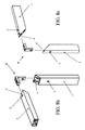
- two profiles 1 can be mutually joined in an angle ⁇ , both along their width ( FIG. 8a ) by inserting the feet 7 inside the respective first, more external profile chambers 3, and along their thickness ( FIG. 8c ) by inserting the feet 7 inside the respective second, more external profile chambers 6.
- connection module 30 is equipped with fastening teeth 31 next to an internal surface with respect to angle ⁇ of each foot 7, also such teeth 31 adapted to be inserted due to elastic distortion or under the thrust of a possible spring (not shown) coaxial with a respective tooth 31 and housed inside the body of the related foot 7, in a corresponding seat 2 of one of the profile chambers 3, 6, 8, 9 inside which the foot 7 must be inserted.
- a possible spring (not shown) coaxial with a respective tooth 31 and housed inside the body of the related foot 7, in a corresponding seat 2 of one of the profile chambers 3, 6, 8, 9 inside which the foot 7 must be inserted.
- FIG. 8b also in this case it is possible to note how two profiles 1 can be mutually joined in an angle ⁇ both along their width ( FIG. 8b ) by inserting the feet 7 inside the respective first, most internal profile chambers 3, and along their thickness (not shown) by inserting the feet 7 inside the respective second, most internal profile chambers 6.
- a fourth connection module 40 of the system according to the present invention is a junction U-bolt composed, in an end thereof, of the insertion foot 7, possibly equipped with at least one fastening tooth 41 adapted to be inserted by elastic distortion or under the thrust of a possible spring (not shown) coaxial with a respective tooth 41 and housed inside the body of the related foot 7, in the corresponding seat 2 of one of the profile chambers 3, 6, 8, 9 inside which the foot 7 must be inserted, and in an opposite end thereof, of a "T"-shaped foot 43 on the surface of which at least one fastening hole 45 is arranged.
- the fourth connection module 40 can be used to connect at least two profiles 1 in a mutually orthogonal position.
- at least one fastening means such as for example a screw 49, in order to grip the fastening hole 45 of the junction U-bolt, this one having its foot 7 inserted at least in the first profile chamber 3, to fasten a second profile 1 orthogonally along its width ( FIG. 10a ) or at least in the second profile chamber 6, to fasten a second profile 1 orthogonally along its thickness ( FIG. 10b ).
- a fifth connection module 50 of the system according to the present invention is a junction square with variable angles along an angle ⁇ , such module 50 being composed of at least two insertion feet 7, each one of which is possibly equipped with at least one fastening tooth 51 adapted to be inserted, due to elastic distortion or under the thrust of a possible spring (not shown), coaxial with a respective tooth 51 and housed inside the body of the related foot 7, in the corresponding seat 2 of one of the profile chambers 3, 6, 8, 9 inside which the foot 7 must be inserted, such feet 7 being mutually connected by interposing at least one articulated junction 53, preferably made as a hinge-type kinematism (such as, for example, in the preferred embodiment shown in FIG. 6 ).
- the articulated junction 53 can obviously be made according to any other equivalent technical solution, such as for example an elastic joint.
- Such junction square with variable angles is adapted to allow the angular union along a variable and adjustable angle ⁇ of at least two profiles 1, possibly suitably shaped at their connection ends to allow a more accurate coupling.
- distance-adjusting means between feet 7 and junction 53 could be inserted.
- each foot 7 could be fully replaced by a respective fourth connection module 40 like the previously described one, in which the distance-adjusting means are made as at least one adjusting screw 55 gripping inside each respective fastening hole 45, possibly cooperating with a respective axially-holding coaxial spring 57.
- two profiles 1 can be mutually joined in an adjustable angle ⁇ , both along their width by inserting the feet 7 inside the respective first, most external ( FIG. 9a ) or most external ( FIG. 9b ) profile chambers 3, and along their thickness, also in this case by inserting the feet 7 inside the respective second, most external ( FIG. 9c ) or most internal (not shown) profile chambers.
Landscapes
- Engineering & Computer Science (AREA)
- Civil Engineering (AREA)
- Structural Engineering (AREA)
- Mutual Connection Of Rods And Tubes (AREA)
- Paper (AREA)
- Magnetic Resonance Imaging Apparatus (AREA)
Applications Claiming Priority (1)
| Application Number | Priority Date | Filing Date | Title |
|---|---|---|---|
| ITTO20070533 ITTO20070533A1 (it) | 2007-07-18 | 2007-07-18 | Sistema multifunzione di assemblaggio di profili. |
Publications (1)
| Publication Number | Publication Date |
|---|---|
| EP2017427A2 true EP2017427A2 (en) | 2009-01-21 |
Family
ID=39708755
Family Applications (1)
| Application Number | Title | Priority Date | Filing Date |
|---|---|---|---|
| EP20080012572 Withdrawn EP2017427A2 (en) | 2007-07-18 | 2008-07-11 | Multi-function system for assembling profiles |
Country Status (2)
| Country | Link |
|---|---|
| EP (1) | EP2017427A2 (it) |
| IT (1) | ITTO20070533A1 (it) |
Cited By (2)
| Publication number | Priority date | Publication date | Assignee | Title |
|---|---|---|---|---|
| DE202011005349U1 (de) * | 2011-04-15 | 2012-07-16 | Rehau Ag + Co | Verbinder zur Erzeugung einer Verbindung zwischen einem Rahmenprofil und einem Rahmen-, Kämpfer-, Pfosten- oder Sprossenprofil eines Fensters oder einer Tür und Verbindung, die einen derartigen Verbinder umfasst |
| EP4098837A4 (en) * | 2020-02-18 | 2023-10-04 | Taroko Door & Window Technologies, Inc. | CONNECTION DEVICE FOR DOOR AND WINDOW FRAMES |
Citations (5)
| Publication number | Priority date | Publication date | Assignee | Title |
|---|---|---|---|---|
| DE3624940A1 (de) | 1986-06-12 | 1987-12-17 | Cordes Werner | Anordnung zum loesbaren verbinden von zwei ineinandersteckbaren profilabschnitten |
| DE4323488A1 (de) | 1993-07-14 | 1995-01-19 | Heinz Zerfas | Montage-Elemente |
| DE19732972A1 (de) | 1997-07-31 | 1999-02-04 | Peter Burger | Bausatz-Profil-System (BPS) für Rahmenkonstruktionen |
| DE10016608A1 (de) | 2000-04-04 | 2001-10-11 | Helmuth Kahl | Spannglied zum stirnseitigen Verbinden von Profilstäben |
| CN1434240A (zh) | 2003-03-09 | 2003-08-06 | 浙江大学 | 多功能型材构件 |
-
2007
- 2007-07-18 IT ITTO20070533 patent/ITTO20070533A1/it unknown
-
2008
- 2008-07-11 EP EP20080012572 patent/EP2017427A2/en not_active Withdrawn
Patent Citations (5)
| Publication number | Priority date | Publication date | Assignee | Title |
|---|---|---|---|---|
| DE3624940A1 (de) | 1986-06-12 | 1987-12-17 | Cordes Werner | Anordnung zum loesbaren verbinden von zwei ineinandersteckbaren profilabschnitten |
| DE4323488A1 (de) | 1993-07-14 | 1995-01-19 | Heinz Zerfas | Montage-Elemente |
| DE19732972A1 (de) | 1997-07-31 | 1999-02-04 | Peter Burger | Bausatz-Profil-System (BPS) für Rahmenkonstruktionen |
| DE10016608A1 (de) | 2000-04-04 | 2001-10-11 | Helmuth Kahl | Spannglied zum stirnseitigen Verbinden von Profilstäben |
| CN1434240A (zh) | 2003-03-09 | 2003-08-06 | 浙江大学 | 多功能型材构件 |
Cited By (3)
| Publication number | Priority date | Publication date | Assignee | Title |
|---|---|---|---|---|
| DE202011005349U1 (de) * | 2011-04-15 | 2012-07-16 | Rehau Ag + Co | Verbinder zur Erzeugung einer Verbindung zwischen einem Rahmenprofil und einem Rahmen-, Kämpfer-, Pfosten- oder Sprossenprofil eines Fensters oder einer Tür und Verbindung, die einen derartigen Verbinder umfasst |
| EP4098837A4 (en) * | 2020-02-18 | 2023-10-04 | Taroko Door & Window Technologies, Inc. | CONNECTION DEVICE FOR DOOR AND WINDOW FRAMES |
| AU2020430412B2 (en) * | 2020-02-18 | 2024-02-29 | Taroko Door & Window Technologies, Inc. | Connection device for door and window frames |
Also Published As
| Publication number | Publication date |
|---|---|
| ITTO20070533A1 (it) | 2007-10-17 |
Similar Documents
| Publication | Publication Date | Title |
|---|---|---|
| US20130272777A1 (en) | Frame connection | |
| US4910876A (en) | Level attachment | |
| CN102947601B (zh) | 用于与框架相互连结的滑动组件 | |
| US5839248A (en) | Frame assembly | |
| ES2954988T3 (es) | Conector operable para acoplar dos o más componentes, y método para acoplar dos o más componentes | |
| US9366022B2 (en) | In-line frame connector assembly and system for large portable frameworks | |
| EP2575544B1 (de) | Verbindungsvorrichtung und schublade mit einer verbindungsvorrichtung | |
| AU2017274579A1 (en) | Panel systems and components | |
| US4098493A (en) | Woven wire partition | |
| EP1619343A2 (en) | System of aluminium framed door/window panels | |
| EP2017427A2 (en) | Multi-function system for assembling profiles | |
| KR20090037222A (ko) | 패널고정장치 | |
| GB2486627A (en) | Frame connection arrangement | |
| KR20090037221A (ko) | 패널고정장치 | |
| JP2020007740A (ja) | 外装用ルーバーの連結装置 | |
| EP2093362A1 (en) | Method and clamping system for the fixation of a hinge or other metal work on profiles for windows and doors | |
| JP4659152B2 (ja) | 管継手 | |
| ES2274004T3 (es) | Dispositivo de fijacion de una pieza de herraje. | |
| SK3698A3 (en) | Mounting for longitudinally grooved cover mouldings | |
| JP2001280005A (ja) | 連窓方立 | |
| US20140356051A1 (en) | Mitered Joint Compression Fastener | |
| JP7340253B2 (ja) | 屋根用雪止め装置 | |
| JP5009086B2 (ja) | 管継手 | |
| CN210512100U (zh) | 型材及中央空调的出风口 | |
| US20060179789A1 (en) | Component for support structure |
Legal Events
| Date | Code | Title | Description |
|---|---|---|---|
| PUAI | Public reference made under article 153(3) epc to a published international application that has entered the european phase |
Free format text: ORIGINAL CODE: 0009012 |
|
| AK | Designated contracting states |
Kind code of ref document: A2 Designated state(s): AT BE BG CH CY CZ DE DK EE ES FI FR GB GR HR HU IE IS IT LI LT LU LV MC MT NL NO PL PT RO SE SI SK TR |
|
| AX | Request for extension of the european patent |
Extension state: AL BA MK RS |
|
| STAA | Information on the status of an ep patent application or granted ep patent |
Free format text: STATUS: THE APPLICATION HAS BEEN WITHDRAWN |
|
| 18W | Application withdrawn |
Effective date: 20130131 |