EP2017433B1 - Aube de turbine à gaz en forme modulaire - Google Patents
Aube de turbine à gaz en forme modulaire Download PDFInfo
- Publication number
- EP2017433B1 EP2017433B1 EP08010396.3A EP08010396A EP2017433B1 EP 2017433 B1 EP2017433 B1 EP 2017433B1 EP 08010396 A EP08010396 A EP 08010396A EP 2017433 B1 EP2017433 B1 EP 2017433B1
- Authority
- EP
- European Patent Office
- Prior art keywords
- turbine blade
- gas
- accordance
- load carrier
- die
- Prior art date
- Legal status (The legal status is an assumption and is not a legal conclusion. Google has not performed a legal analysis and makes no representation as to the accuracy of the status listed.)
- Ceased
Links
- OKTJSMMVPCPJKN-UHFFFAOYSA-N Carbon Chemical compound [C] OKTJSMMVPCPJKN-UHFFFAOYSA-N 0.000 claims description 18
- 238000001816 cooling Methods 0.000 claims description 17
- 239000002041 carbon nanotube Substances 0.000 claims description 16
- 229910021393 carbon nanotube Inorganic materials 0.000 claims description 16
- 238000000034 method Methods 0.000 claims description 5
- 229910052799 carbon Inorganic materials 0.000 claims 2
- 229910010293 ceramic material Inorganic materials 0.000 claims 1
- 238000010276 construction Methods 0.000 description 14
- 238000004519 manufacturing process Methods 0.000 description 12
- 239000000463 material Substances 0.000 description 11
- 239000000835 fiber Substances 0.000 description 8
- 230000008901 benefit Effects 0.000 description 6
- 238000005266 casting Methods 0.000 description 6
- 238000005242 forging Methods 0.000 description 5
- 239000000243 solution Substances 0.000 description 5
- 238000005495 investment casting Methods 0.000 description 3
- 238000003754 machining Methods 0.000 description 3
- 229910000831 Steel Inorganic materials 0.000 description 2
- 208000012886 Vertigo Diseases 0.000 description 2
- 239000006096 absorbing agent Substances 0.000 description 2
- 229910045601 alloy Inorganic materials 0.000 description 2
- 239000000956 alloy Substances 0.000 description 2
- 239000000919 ceramic Substances 0.000 description 2
- 239000011248 coating agent Substances 0.000 description 2
- 238000000576 coating method Methods 0.000 description 2
- 239000013078 crystal Substances 0.000 description 2
- 239000011159 matrix material Substances 0.000 description 2
- 238000003801 milling Methods 0.000 description 2
- 230000008439 repair process Effects 0.000 description 2
- 230000035939 shock Effects 0.000 description 2
- 239000010959 steel Substances 0.000 description 2
- 238000005486 sulfidation Methods 0.000 description 2
- 241000191291 Abies alba Species 0.000 description 1
- 229920000049 Carbon (fiber) Polymers 0.000 description 1
- 101100390736 Danio rerio fign gene Proteins 0.000 description 1
- 241001295925 Gegenes Species 0.000 description 1
- 101100390738 Mus musculus Fign gene Proteins 0.000 description 1
- 230000002411 adverse Effects 0.000 description 1
- 239000011230 binding agent Substances 0.000 description 1
- 239000004917 carbon fiber Substances 0.000 description 1
- 230000006835 compression Effects 0.000 description 1
- 238000007906 compression Methods 0.000 description 1
- 230000008602 contraction Effects 0.000 description 1
- 230000007797 corrosion Effects 0.000 description 1
- 238000005260 corrosion Methods 0.000 description 1
- 238000005520 cutting process Methods 0.000 description 1
- 238000013016 damping Methods 0.000 description 1
- 230000007812 deficiency Effects 0.000 description 1
- 230000001419 dependent effect Effects 0.000 description 1
- 230000006866 deterioration Effects 0.000 description 1
- 230000000694 effects Effects 0.000 description 1
- 230000007246 mechanism Effects 0.000 description 1
- 239000002184 metal Substances 0.000 description 1
- 229910001235 nimonic Inorganic materials 0.000 description 1
- 238000005457 optimization Methods 0.000 description 1
- 230000003647 oxidation Effects 0.000 description 1
- 238000007254 oxidation reaction Methods 0.000 description 1
- 238000005498 polishing Methods 0.000 description 1
- 238000000926 separation method Methods 0.000 description 1
- 210000002023 somite Anatomy 0.000 description 1
- 239000002344 surface layer Substances 0.000 description 1
- 238000004381 surface treatment Methods 0.000 description 1
Images


Classifications
-
- F—MECHANICAL ENGINEERING; LIGHTING; HEATING; WEAPONS; BLASTING
- F01—MACHINES OR ENGINES IN GENERAL; ENGINE PLANTS IN GENERAL; STEAM ENGINES
- F01D—NON-POSITIVE DISPLACEMENT MACHINES OR ENGINES, e.g. STEAM TURBINES
- F01D5/00—Blades; Blade-carrying members; Heating, heat-insulating, cooling or antivibration means on the blades or the members
- F01D5/12—Blades
- F01D5/28—Selecting particular materials; Particular measures relating thereto; Measures against erosion or corrosion
- F01D5/284—Selection of ceramic materials
-
- F—MECHANICAL ENGINEERING; LIGHTING; HEATING; WEAPONS; BLASTING
- F01—MACHINES OR ENGINES IN GENERAL; ENGINE PLANTS IN GENERAL; STEAM ENGINES
- F01D—NON-POSITIVE DISPLACEMENT MACHINES OR ENGINES, e.g. STEAM TURBINES
- F01D5/00—Blades; Blade-carrying members; Heating, heat-insulating, cooling or antivibration means on the blades or the members
- F01D5/12—Blades
- F01D5/14—Form or construction
- F01D5/147—Construction, i.e. structural features, e.g. of weight-saving hollow blades
-
- F—MECHANICAL ENGINEERING; LIGHTING; HEATING; WEAPONS; BLASTING
- F01—MACHINES OR ENGINES IN GENERAL; ENGINE PLANTS IN GENERAL; STEAM ENGINES
- F01D—NON-POSITIVE DISPLACEMENT MACHINES OR ENGINES, e.g. STEAM TURBINES
- F01D5/00—Blades; Blade-carrying members; Heating, heat-insulating, cooling or antivibration means on the blades or the members
- F01D5/12—Blades
- F01D5/28—Selecting particular materials; Particular measures relating thereto; Measures against erosion or corrosion
- F01D5/282—Selecting composite materials, e.g. blades with reinforcing filaments
-
- F—MECHANICAL ENGINEERING; LIGHTING; HEATING; WEAPONS; BLASTING
- F05—INDEXING SCHEMES RELATING TO ENGINES OR PUMPS IN VARIOUS SUBCLASSES OF CLASSES F01-F04
- F05D—INDEXING SCHEME FOR ASPECTS RELATING TO NON-POSITIVE-DISPLACEMENT MACHINES OR ENGINES, GAS-TURBINES OR JET-PROPULSION PLANTS
- F05D2230/00—Manufacture
- F05D2230/60—Assembly methods
-
- F—MECHANICAL ENGINEERING; LIGHTING; HEATING; WEAPONS; BLASTING
- F05—INDEXING SCHEMES RELATING TO ENGINES OR PUMPS IN VARIOUS SUBCLASSES OF CLASSES F01-F04
- F05D—INDEXING SCHEME FOR ASPECTS RELATING TO NON-POSITIVE-DISPLACEMENT MACHINES OR ENGINES, GAS-TURBINES OR JET-PROPULSION PLANTS
- F05D2300/00—Materials; Properties thereof
- F05D2300/20—Oxide or non-oxide ceramics
- F05D2300/21—Oxide ceramics
-
- F—MECHANICAL ENGINEERING; LIGHTING; HEATING; WEAPONS; BLASTING
- F05—INDEXING SCHEMES RELATING TO ENGINES OR PUMPS IN VARIOUS SUBCLASSES OF CLASSES F01-F04
- F05D—INDEXING SCHEME FOR ASPECTS RELATING TO NON-POSITIVE-DISPLACEMENT MACHINES OR ENGINES, GAS-TURBINES OR JET-PROPULSION PLANTS
- F05D2300/00—Materials; Properties thereof
- F05D2300/60—Properties or characteristics given to material by treatment or manufacturing
- F05D2300/603—Composites; e.g. fibre-reinforced
-
- Y—GENERAL TAGGING OF NEW TECHNOLOGICAL DEVELOPMENTS; GENERAL TAGGING OF CROSS-SECTIONAL TECHNOLOGIES SPANNING OVER SEVERAL SECTIONS OF THE IPC; TECHNICAL SUBJECTS COVERED BY FORMER USPC CROSS-REFERENCE ART COLLECTIONS [XRACs] AND DIGESTS
- Y02—TECHNOLOGIES OR APPLICATIONS FOR MITIGATION OR ADAPTATION AGAINST CLIMATE CHANGE
- Y02T—CLIMATE CHANGE MITIGATION TECHNOLOGIES RELATED TO TRANSPORTATION
- Y02T50/00—Aeronautics or air transport
- Y02T50/60—Efficient propulsion technologies, e.g. for aircraft
Definitions
- the invention relates to a gas turbine blade according to the preamble of claim 1.
- the invention relates to a gas turbine blade with an airfoil, which is provided radially outboard with a shroud and is mounted radially inwardly of a platform.
- the platform in turn is provided with a foot by means of a shaft (inner load carrier) 6 and anchored to a disc, as known from the prior art.
- Compressor blades are typically made from forgings and have thin, radially stacked cross sections.
- Turbine blades are typically made from complex investment casting ( Fig. 1 ) using a wax-melt casting method. This is very time consuming and costly.
- turbine blades In order to cope with creep and the adverse effects of the hot gas environment, turbine blades have radially stacked and thicker cross sections than compressor blades. They include cooling air ejection holes (cooling of the surface layer and the outlet edge ejection), which require additional internally cast cooling air supply passages. The pressure difference is always positive, so that cooling air always exits out into the gas path.
- Turbine blades are typically manufactured as equiaxed, aligned solidified, or single crystal castings. These castings are then finished by machining and polishing the airfoil surfaces to obtain a high degree of surface treatment. Finally, to avoid sulfidation and oxidation, the blades are coated with a thin and expensive aluminized coating.
- the lost-wax casting method is a manual, time-consuming and labor-intensive manufacturing process that sometimes leads to deficiency, such as shrinkage, especially when internal cooling passages are involved.
- the side wall wings of the blades must be quite thick in cross section, increasing the weight and the CF drag on the fir tree feet of the blades is increased due to the increased weight of the blade.
- the US Pat. No. 4,519,745 A shows a structure with a load carrier, which is surrounded by a cooling air cavity.
- the GB 2 084 262 A shows a very similar construction.
- the US 3 567 333 A shows a similar construction with a support defining individual cooling air channels.
- the FR 51 723 E shows a similar construction with a load carrier and a surrounding blade element. From the US 4,285,634 It is known to provide individual bars to connect an outdoor platform to one foot.
- the US Pat. No. 3,950,113 shows a construction in which a centric carrier is integrally connected to the foot.
- Other solutions are from the FR 2 463 849 A1 previously known.
- the GB 625 693 A shows a construction with a centric carrier and surrounding air ducts and a blade element.
- the invention has for its object to provide a gas turbine blade of the type mentioned, which avoids the disadvantages of the prior art with a simple structure and simple, cost-effective manufacturability.
- the invention thus relates to a novel design and a new manufacturing method for turbine blades.
- turbine blades are constructed and manufactured from separate modular parts which are subsequently assembled together to form a complete turbine blade assembly.
- This modular design principle can be used for blades for blowers and compressors.
- the biggest benefit in terms of cost, performance, and manufacturing is currently achieved in turbine blade design.
- the centrifugal force tensile load due to the rotational speed is carried by a radially disposed, central and / or disposed between the inner and outer platform module shaft module.
- This central shaft module lies in the interior of the airfoil-shaped bushing module and is cooled on the outside by cooling air which flows into the blade cavity around the central shaft (inner load carrier) 6.
- the aerodynamic loads are carried by an internally cooled, wing-shaped bushing module.
- the bush is subject to aerodynamic loads as well as a compressive centrifugal force load due to its own weight and sliding inner end structure.
- these compressive loads are typically only 10% of the centrifugal force tensile loads.
- the expansion of the sleeve due to the temperature compensates for the contraction due to the centrifugal force tensile loads.
- the Fig. 1 shows a perspective view of a gas turbine blade according to the prior art. This comprises a shroud 1, an airfoil 2, a platform 3, a shaft 4 and a foot 5, which is designed as Tannenbaumfuß.
- the Fig. 2 shows occurring loads of a gas turbine blade according to the prior art.
- a gas load 21 (large arrow) results in a moment arm 22 for the gas load.
- a centrifugal force 24 which is associated with a centrifugal force moment arm 25.
- Reference numeral 26 denotes a centrifugal force force pair
- a gas force force pair is denoted by 27.
- the reference numeral 28 shows a clamping region of the blade root 5 to be compensated.
- FIGS. 3A to 3D each show arrows A to F, which illustrate the manufacturing steps:
- Fig. 3A it is provided that in the steps A and B, the halves of the inner platform 3 are joined together so that grooves 12 engage a base 13 of the foot 5.
- step C a locking takes place
- step D the aerodynamic blade element 8 is inserted into the grooves 11 of the inner platform 3.
- step E the outer platform 10 is attached, so that the leaf element 8 is inserted into the groove 9 and a radially outer base 15 of the inner load carrier 6 is inserted into a recess 14 of the outer platform 10.
- step F a seal is carried out.
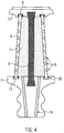
- the Fig. 4 shows an assembly drawing of an embodiment of a gas turbine blade according to the invention.
Landscapes
- Engineering & Computer Science (AREA)
- Chemical & Material Sciences (AREA)
- Mechanical Engineering (AREA)
- General Engineering & Computer Science (AREA)
- Materials Engineering (AREA)
- Architecture (AREA)
- Composite Materials (AREA)
- Ceramic Engineering (AREA)
- Turbine Rotor Nozzle Sealing (AREA)
- Structures Of Non-Positive Displacement Pumps (AREA)
Claims (10)
- Aube de turbine à gaz avec un pied (5) et une pale (2), sachant que la pale (2) comprend un porte-charge (6) situé à l'intérieur ainsi qu'un élément de pale (8) entourant celui-ci en formant un espace creux (7) s'étendant dans l'axe longitudinal de l'aube, sachant que le porte-charge (6) est conçu sous forme d'élément central sans canaux de refroidissement et que l'air de refroidissement est introduit dans l'espace creux par le pied (5), caractérisée en ce que le porte-charge (6) est fabriqué en fibres de carbone, sachant que le porte-charge (6) est constitué de fibres creuses de carbone qui sont fabriquées sous forme de faisceaux de fibres tordus en nanotubes de carbone.
- Aube de turbine à gaz selon la revendication n° 1, caractérisée en ce que l'air de refroidissement est introduit à travers une plate-forme (3) du pied (5).
- Aube de turbine à gaz selon une des revendications n° 1 ou n° 2, caractérisée en ce que l'élément de pale (8) au niveau de son extrémité radialement extérieure, est monté sur la plate-forme extérieure (10).
- Aube de turbine à gaz selon la revendication n° 3, caractérisée en ce que l'élément de pale (8) peut être soumis à une charge de compression en fonctionnement.
- Aube de turbine à gaz selon la revendication n° 3 ou n° 4, caractérisée en ce que l'élément de pale (8) au niveau de son extrémité radialement intérieure, est monté de manière déplaçable sur une plate-forme intérieure (3).
- Aube de turbine à gaz selon une des revendications n° 1 à n° 5, caractérisée en ce que l'élément de pale (8) est conçu en plusieurs pièces.
- Aube de turbine à gaz selon la revendication n° 6, caractérisée en ce que l'élément de pale (8) est réalisable au moyen d'un procédé d'assemblage.
- Aube de turbine à gaz selon une des revendications n° 1 à n° 7, caractérisée en ce que l'élément de pale (8) est fabriqué en un matériau céramique.
- Aube de turbine à gaz selon une des revendications n° 1 à n° 8, caractérisée en ce que le porte-charge (6) est relié à un support de palier radialement extérieur, en forme de plate-forme extérieure (10).
- Aube de turbine à gaz selon une des revendications n° 1 à n° 9, caractérisée en ce que le porte-charge (6), au niveau de son extrémité radialement intérieure, est relié au pied (5) par engagement positif.
Applications Claiming Priority (1)
| Application Number | Priority Date | Filing Date | Title |
|---|---|---|---|
| DE102007027465A DE102007027465A1 (de) | 2007-06-14 | 2007-06-14 | Gasturbinenschaufel mit modularem Aufbau |
Publications (3)
| Publication Number | Publication Date |
|---|---|
| EP2017433A2 EP2017433A2 (fr) | 2009-01-21 |
| EP2017433A3 EP2017433A3 (fr) | 2012-07-04 |
| EP2017433B1 true EP2017433B1 (fr) | 2018-11-21 |
Family
ID=39764680
Family Applications (1)
| Application Number | Title | Priority Date | Filing Date |
|---|---|---|---|
| EP08010396.3A Ceased EP2017433B1 (fr) | 2007-06-14 | 2008-06-06 | Aube de turbine à gaz en forme modulaire |
Country Status (3)
| Country | Link |
|---|---|
| US (1) | US8100653B2 (fr) |
| EP (1) | EP2017433B1 (fr) |
| DE (1) | DE102007027465A1 (fr) |
Families Citing this family (22)
| Publication number | Priority date | Publication date | Assignee | Title |
|---|---|---|---|---|
| US7967565B1 (en) * | 2009-03-20 | 2011-06-28 | Florida Turbine Technologies, Inc. | Low cooling flow turbine blade |
| US8678764B1 (en) * | 2009-10-27 | 2014-03-25 | Florida Turbine Technologies, Inc. | Tip cap for a turbine rotor blade |
| BR112012017122B1 (pt) | 2010-01-14 | 2021-09-28 | Senvion Gmbh | Feixe compósito para uma pá de turbina eólica |
| US10137542B2 (en) | 2010-01-14 | 2018-11-27 | Senvion Gmbh | Wind turbine rotor blade components and machine for making same |
| US8475132B2 (en) * | 2011-03-16 | 2013-07-02 | General Electric Company | Turbine blade assembly |
| JP6120942B2 (ja) | 2012-03-28 | 2017-04-26 | ゼネラル エレクトリック テクノロジー ゲゼルシャフト ミット ベシュレンクテル ハフツングGeneral Electric Technology GmbH | セラミックス部分から金属部分を分離する方法 |
| WO2013144035A1 (fr) * | 2012-03-28 | 2013-10-03 | Alstom Technology Ltd | Procédé de traitement d'un élément hybride modulaire |
| US10605086B2 (en) | 2012-11-20 | 2020-03-31 | Honeywell International Inc. | Turbine engines with ceramic vanes and methods for manufacturing the same |
| US20140255194A1 (en) * | 2012-12-21 | 2014-09-11 | General Electric Company | Tip shrouds of turbine rotor blades and methods of manufacture related thereto |
| US10329925B2 (en) * | 2013-07-15 | 2019-06-25 | United Technologies Corporation | Vibration-damped composite airfoils and manufacture methods |
| US10072503B2 (en) | 2013-08-14 | 2018-09-11 | Elwha Llc | Dual element turbine blade |
| EP3058177B1 (fr) | 2013-10-18 | 2023-11-29 | RTX Corporation | Procédé de formation d'un composant d'un moteur à turbine à gaz |
| US10731481B2 (en) * | 2016-11-01 | 2020-08-04 | Rolls-Royce Corporation | Turbine blade with ceramic matrix composite material construction |
| FR3067389B1 (fr) * | 2017-04-10 | 2021-10-29 | Safran | Aube de turbine presentant une structure amelioree |
| US10724380B2 (en) * | 2017-08-07 | 2020-07-28 | General Electric Company | CMC blade with internal support |
| US10724387B2 (en) * | 2018-11-08 | 2020-07-28 | Raytheon Technologies Corporation | Continuation of a shear tube through a vane platform for structural support |
| EP3751098A1 (fr) * | 2019-06-13 | 2020-12-16 | Siemens Aktiengesellschaft | Lame améliorée |
| US11346227B2 (en) * | 2019-12-19 | 2022-05-31 | Power Systems Mfg., Llc | Modular components for gas turbine engines and methods of manufacturing the same |
| US12146419B1 (en) * | 2020-01-07 | 2024-11-19 | Rtx Corporation | Multi-alloy turbine engine components and manufacture methods |
| US12173621B2 (en) * | 2021-06-04 | 2024-12-24 | Rtx Corporation | Hybrid platform manufacturing |
| FR3127022A1 (fr) * | 2021-09-15 | 2023-03-17 | Safran Aircraft Engines | Aube comprenant des becquets rapportés |
| US20260071548A1 (en) * | 2024-09-06 | 2026-03-12 | General Electric Company | Airfoils for gas turbine engines |
Citations (1)
| Publication number | Priority date | Publication date | Assignee | Title |
|---|---|---|---|---|
| US6821087B2 (en) * | 2002-01-21 | 2004-11-23 | Honda Giken Kogyo Kabushiki Kaisha | Flow-rectifying member and its unit and method for producing flow-rectifying member |
Family Cites Families (16)
| Publication number | Priority date | Publication date | Assignee | Title |
|---|---|---|---|---|
| FR51723E (fr) * | 1941-08-14 | 1943-04-09 | Bmw Flugmotorenbau Gmbh | Aube de rotor pour turbines à gaz d'échappement |
| GB625693A (en) * | 1946-10-25 | 1949-07-01 | Brush Electrical Eng | Improvements in and relating to turbine blades |
| BE487558A (fr) | 1948-03-03 | |||
| DE1801475B2 (de) * | 1968-10-05 | 1971-08-12 | Daimler Benz Ag, 7000 Stuttgart | Luftgekuehlte turbinenschaufel |
| US3567333A (en) | 1969-01-31 | 1971-03-02 | Curtiss Wright Corp | Gas turbine blade |
| DE2834864C3 (de) * | 1978-08-09 | 1981-11-19 | MTU Motoren- und Turbinen-Union München GmbH, 8000 München | Laufschaufel für eine Gasturbine |
| GB2050529B (en) | 1979-05-04 | 1983-08-03 | English Electric Co Ltd | Gas turbine blade |
| FR2463849A1 (fr) * | 1979-08-23 | 1981-02-27 | Onera (Off Nat Aerospatiale) | Perfectionnements apportes aux aubes tournantes de turbines a gaz, et aux turbines a gaz equipees de ces aubes |
| US4519745A (en) * | 1980-09-19 | 1985-05-28 | Rockwell International Corporation | Rotor blade and stator vane using ceramic shell |
| FR2490721B1 (fr) * | 1980-09-19 | 1987-10-09 | Rockwell International Corp | Turbomachine dont les aubages mobile et fixe sont proteges par une carapace en ceramique |
| DE3306896A1 (de) * | 1983-02-26 | 1984-08-30 | MTU Motoren- und Turbinen-Union München GmbH, 8000 München | Heissgasbeaufschlagte turbinenschaufel mit metallenem stuetzkern und umgebendem keramischen schaufelblatt |
| US6514046B1 (en) | 2000-09-29 | 2003-02-04 | Siemens Westinghouse Power Corporation | Ceramic composite vane with metallic substructure |
| US7080971B2 (en) | 2003-03-12 | 2006-07-25 | Florida Turbine Technologies, Inc. | Cooled turbine spar shell blade construction |
| US7186082B2 (en) * | 2004-05-27 | 2007-03-06 | United Technologies Corporation | Cooled rotor blade and method for cooling a rotor blade |
| US7431562B2 (en) * | 2005-12-21 | 2008-10-07 | General Electric Company | Method and apparatus for cooling gas turbine rotor blades |
| US7452189B2 (en) | 2006-05-03 | 2008-11-18 | United Technologies Corporation | Ceramic matrix composite turbine engine vane |
-
2007
- 2007-06-14 DE DE102007027465A patent/DE102007027465A1/de not_active Withdrawn
-
2008
- 2008-06-06 EP EP08010396.3A patent/EP2017433B1/fr not_active Ceased
- 2008-06-12 US US12/213,004 patent/US8100653B2/en not_active Expired - Fee Related
Patent Citations (1)
| Publication number | Priority date | Publication date | Assignee | Title |
|---|---|---|---|---|
| US6821087B2 (en) * | 2002-01-21 | 2004-11-23 | Honda Giken Kogyo Kabushiki Kaisha | Flow-rectifying member and its unit and method for producing flow-rectifying member |
Also Published As
| Publication number | Publication date |
|---|---|
| US20080310965A1 (en) | 2008-12-18 |
| EP2017433A2 (fr) | 2009-01-21 |
| US8100653B2 (en) | 2012-01-24 |
| DE102007027465A1 (de) | 2008-12-18 |
| EP2017433A3 (fr) | 2012-07-04 |
Similar Documents
| Publication | Publication Date | Title |
|---|---|---|
| EP2017433A2 (fr) | Aube de turbine à gaz en forme modulaire | |
| EP2719484B1 (fr) | Composant pour turbomachine | |
| EP1355043B1 (fr) | Aube de rotor pour une turbomachine | |
| EP2024608B1 (fr) | Turbocompresseur en montage axial | |
| EP2853688A2 (fr) | Aube pour une turbine à gaz | |
| DE3940981C2 (de) | Auswuchtgewicht zum Auswuchten des Rotors eines Gasturbinentriebwerks | |
| DE602004006323T2 (de) | Verfahren zur Herstellung einer Turbine mit Turbinenschaufeln unterschiedlicher Resonanzfrequenzen samt einer solchen Turbine | |
| EP1032749B1 (fr) | Rotor a aubes integrees | |
| DE69616460T2 (de) | Rotor aus thermostrukturellem Verbundmaterial, insbesondere mit grossem Diameter und sein Herstellungsverfahren | |
| EP3191244B1 (fr) | Procédé de production d'une aube mobile et aube obtenue | |
| EP2499378B1 (fr) | Carter de turbocompresseur | |
| DE60302525T2 (de) | Trommelrotor für eine Turbomaschine | |
| EP0629770A2 (fr) | Procédé pour la préparation d'un anneau à aubes pour des rotors tambour d'une turbomachine | |
| EP1707745A2 (fr) | Aube de rotor pour une turbomachine et turbomachine | |
| DE102012011952B4 (de) | Turbinenschaufelblatt aus Verbundwerkstoff | |
| EP1489264A1 (fr) | Aube constituèe des modules | |
| DE10361882B4 (de) | Rotor für die Hochdruckturbine eines Flugtriebwerks | |
| DE2753773A1 (de) | Laufschaufel | |
| EP1531234B1 (fr) | Virole interne pour les aubes statoriques d'un compresseur de turbine à gaz | |
| DE3305880A1 (de) | Befestigungsanordnung fuer turbinenschaufeln | |
| EP3067519B1 (fr) | Pale de soufflante pour une propulsion aéronautique | |
| EP1816401B1 (fr) | Turbomachine | |
| EP2356319A1 (fr) | Dispositif d'aubes directrices pour turbomachine axiale | |
| EP1764479A1 (fr) | Plaques de virole couplées pour une série d'aubes d'une turbomachine | |
| DE602004007071T2 (de) | Zwischenschaufelplattformen mit elastischen Seitenkanten |
Legal Events
| Date | Code | Title | Description |
|---|---|---|---|
| PUAI | Public reference made under article 153(3) epc to a published international application that has entered the european phase |
Free format text: ORIGINAL CODE: 0009012 |
|
| PUAI | Public reference made under article 153(3) epc to a published international application that has entered the european phase |
Free format text: ORIGINAL CODE: 0009012 |
|
| AK | Designated contracting states |
Kind code of ref document: A2 Designated state(s): AT BE BG CH CY CZ DE DK EE ES FI FR GB GR HR HU IE IS IT LI LT LU LV MC MT NL NO PL PT RO SE SI SK TR |
|
| AX | Request for extension of the european patent |
Extension state: AL BA MK RS |
|
| RIC1 | Information provided on ipc code assigned before grant |
Ipc: F01D 5/28 20060101ALI20120424BHEP Ipc: F01D 5/14 20060101AFI20120424BHEP |
|
| PUAL | Search report despatched |
Free format text: ORIGINAL CODE: 0009013 |
|
| AK | Designated contracting states |
Kind code of ref document: A3 Designated state(s): AT BE BG CH CY CZ DE DK EE ES FI FR GB GR HR HU IE IS IT LI LT LU LV MC MT NL NO PL PT RO SE SI SK TR |
|
| AX | Request for extension of the european patent |
Extension state: AL BA MK RS |
|
| RIC1 | Information provided on ipc code assigned before grant |
Ipc: F01D 5/14 20060101AFI20120525BHEP Ipc: F01D 5/28 20060101ALI20120525BHEP |
|
| 17P | Request for examination filed |
Effective date: 20121227 |
|
| AKX | Designation fees paid |
Designated state(s): DE FR GB |
|
| 17Q | First examination report despatched |
Effective date: 20171025 |
|
| GRAP | Despatch of communication of intention to grant a patent |
Free format text: ORIGINAL CODE: EPIDOSNIGR1 |
|
| INTG | Intention to grant announced |
Effective date: 20180619 |
|
| RIN1 | Information on inventor provided before grant (corrected) |
Inventor name: GERAKIS, JEFFREY-GEORGE Inventor name: DAVISON, PETER |
|
| GRAS | Grant fee paid |
Free format text: ORIGINAL CODE: EPIDOSNIGR3 |
|
| GRAA | (expected) grant |
Free format text: ORIGINAL CODE: 0009210 |
|
| AK | Designated contracting states |
Kind code of ref document: B1 Designated state(s): DE FR GB |
|
| REG | Reference to a national code |
Ref country code: DE Ref legal event code: R096 Ref document number: 502008016466 Country of ref document: DE |
|
| REG | Reference to a national code |
Ref country code: DE Ref legal event code: R097 Ref document number: 502008016466 Country of ref document: DE |
|
| PGFP | Annual fee paid to national office [announced via postgrant information from national office to epo] |
Ref country code: FR Payment date: 20190625 Year of fee payment: 12 |
|
| PLBE | No opposition filed within time limit |
Free format text: ORIGINAL CODE: 0009261 |
|
| STAA | Information on the status of an ep patent application or granted ep patent |
Free format text: STATUS: NO OPPOSITION FILED WITHIN TIME LIMIT |
|
| 26N | No opposition filed |
Effective date: 20190822 |
|
| PGFP | Annual fee paid to national office [announced via postgrant information from national office to epo] |
Ref country code: GB Payment date: 20190627 Year of fee payment: 12 Ref country code: DE Payment date: 20190627 Year of fee payment: 12 |
|
| REG | Reference to a national code |
Ref country code: DE Ref legal event code: R082 Ref document number: 502008016466 Country of ref document: DE |
|
| REG | Reference to a national code |
Ref country code: DE Ref legal event code: R119 Ref document number: 502008016466 Country of ref document: DE |
|
| GBPC | Gb: european patent ceased through non-payment of renewal fee |
Effective date: 20200606 |
|
| PG25 | Lapsed in a contracting state [announced via postgrant information from national office to epo] |
Ref country code: FR Free format text: LAPSE BECAUSE OF NON-PAYMENT OF DUE FEES Effective date: 20200630 Ref country code: GB Free format text: LAPSE BECAUSE OF NON-PAYMENT OF DUE FEES Effective date: 20200606 |
|
| PG25 | Lapsed in a contracting state [announced via postgrant information from national office to epo] |
Ref country code: DE Free format text: LAPSE BECAUSE OF NON-PAYMENT OF DUE FEES Effective date: 20210101 |