EP2017460B1 - Dispositif d'admission de moteur à combustion interne - Google Patents
Dispositif d'admission de moteur à combustion interne Download PDFInfo
- Publication number
- EP2017460B1 EP2017460B1 EP08012945A EP08012945A EP2017460B1 EP 2017460 B1 EP2017460 B1 EP 2017460B1 EP 08012945 A EP08012945 A EP 08012945A EP 08012945 A EP08012945 A EP 08012945A EP 2017460 B1 EP2017460 B1 EP 2017460B1
- Authority
- EP
- European Patent Office
- Prior art keywords
- negative pressure
- outlet port
- pressure outlet
- projecting portion
- passage
- Prior art date
- Legal status (The legal status is an assumption and is not a legal conclusion. Google has not performed a legal analysis and makes no representation as to the accuracy of the status listed.)
- Ceased
Links
Images


Classifications
-
- F—MECHANICAL ENGINEERING; LIGHTING; HEATING; WEAPONS; BLASTING
- F02—COMBUSTION ENGINES; HOT-GAS OR COMBUSTION-PRODUCT ENGINE PLANTS
- F02M—SUPPLYING COMBUSTION ENGINES IN GENERAL WITH COMBUSTIBLE MIXTURES OR CONSTITUENTS THEREOF
- F02M35/00—Combustion-air cleaners, air intakes, intake silencers, or induction systems specially adapted for, or arranged on, internal-combustion engines
- F02M35/10—Air intakes; Induction systems
- F02M35/104—Intake manifolds
- F02M35/112—Intake manifolds for engines with cylinders all in one line
-
- F—MECHANICAL ENGINEERING; LIGHTING; HEATING; WEAPONS; BLASTING
- F02—COMBUSTION ENGINES; HOT-GAS OR COMBUSTION-PRODUCT ENGINE PLANTS
- F02M—SUPPLYING COMBUSTION ENGINES IN GENERAL WITH COMBUSTIBLE MIXTURES OR CONSTITUENTS THEREOF
- F02M35/00—Combustion-air cleaners, air intakes, intake silencers, or induction systems specially adapted for, or arranged on, internal-combustion engines
- F02M35/10—Air intakes; Induction systems
- F02M35/10209—Fluid connections to the air intake system; their arrangement of pipes, valves or the like
- F02M35/10222—Exhaust gas recirculation [EGR]; Positive crankcase ventilation [PCV]; Additional air admission, lubricant or fuel vapour admission
-
- F—MECHANICAL ENGINEERING; LIGHTING; HEATING; WEAPONS; BLASTING
- F02—COMBUSTION ENGINES; HOT-GAS OR COMBUSTION-PRODUCT ENGINE PLANTS
- F02M—SUPPLYING COMBUSTION ENGINES IN GENERAL WITH COMBUSTIBLE MIXTURES OR CONSTITUENTS THEREOF
- F02M35/00—Combustion-air cleaners, air intakes, intake silencers, or induction systems specially adapted for, or arranged on, internal-combustion engines
- F02M35/10—Air intakes; Induction systems
- F02M35/10209—Fluid connections to the air intake system; their arrangement of pipes, valves or the like
- F02M35/10229—Fluid connections to the air intake system; their arrangement of pipes, valves or the like the intake system acting as a vacuum or overpressure source for auxiliary devices, e.g. brake systems; Vacuum chambers
-
- F—MECHANICAL ENGINEERING; LIGHTING; HEATING; WEAPONS; BLASTING
- F02—COMBUSTION ENGINES; HOT-GAS OR COMBUSTION-PRODUCT ENGINE PLANTS
- F02M—SUPPLYING COMBUSTION ENGINES IN GENERAL WITH COMBUSTIBLE MIXTURES OR CONSTITUENTS THEREOF
- F02M35/00—Combustion-air cleaners, air intakes, intake silencers, or induction systems specially adapted for, or arranged on, internal-combustion engines
- F02M35/10—Air intakes; Induction systems
- F02M35/10314—Materials for intake systems
- F02M35/10321—Plastics; Composites; Rubbers
-
- F—MECHANICAL ENGINEERING; LIGHTING; HEATING; WEAPONS; BLASTING
- F02—COMBUSTION ENGINES; HOT-GAS OR COMBUSTION-PRODUCT ENGINE PLANTS
- F02M—SUPPLYING COMBUSTION ENGINES IN GENERAL WITH COMBUSTIBLE MIXTURES OR CONSTITUENTS THEREOF
- F02M35/00—Combustion-air cleaners, air intakes, intake silencers, or induction systems specially adapted for, or arranged on, internal-combustion engines
- F02M35/10—Air intakes; Induction systems
- F02M35/1034—Manufacturing and assembling intake systems
- F02M35/10354—Joining multiple sections together
- F02M35/1036—Joining multiple sections together by welding, bonding or the like
-
- F—MECHANICAL ENGINEERING; LIGHTING; HEATING; WEAPONS; BLASTING
- F02—COMBUSTION ENGINES; HOT-GAS OR COMBUSTION-PRODUCT ENGINE PLANTS
- F02M—SUPPLYING COMBUSTION ENGINES IN GENERAL WITH COMBUSTIBLE MIXTURES OR CONSTITUENTS THEREOF
- F02M35/00—Combustion-air cleaners, air intakes, intake silencers, or induction systems specially adapted for, or arranged on, internal-combustion engines
- F02M35/02—Air cleaners
Definitions
- the present invention relates to an intake device provided in an internal combustion engine and more particularly to a waterproof construction provided in an intake device which is provided with a negative pressure outlet port for taking out negative pressure generated in an intake passage for preventing water from entering into the negative pressure outlet port.
- a projecting portion for example, a baffle plate
- the recessed portion is enlarged and the disposition of the negative pressure outlet port in the intake device becomes restricted.
- the construction of the recessed portion becomes complex and the production costs of the intake device increases.
- the projecting portion may be damaged when handling the passage wall, depending upon locations where the projecting portion is provided which makes up the waterproof construction, it is desirable to avoid such damage.
- the present invention aims to suppress the increase in passage resistance of the intake passage and to reduce the production costs.
- the present invention also aims to increase further the effect of preventing the entering of water drops into the negative pressure outlet port by the waterproof construction. Further, the present invention aims to avoid the damage to the protrusion formed on the passage walls during handling.
- an intake device of an internal combustion engine including:
- water drops falling along the inner surface of the upper passage wall towards the negative pressure outlet port flow downwards along the projecting portion which is situated closer to the intake passage side than the negative pressure outlet port and fall from the lower end portion of the projecting portion towards therebelow. Therefore, water drops are restrained from entering into the negative pressure outlet port which lies deeper than the projecting portion within the recessed portion. Accordingly, the reduction in performance of the function of taking out negative pressure is prevented which would otherwise be caused by water drops which have entered from the negative pressure outlet port and become frozen. Further, the projecting portion is accommodated within the recessed portion and does not project into the intake passage from the inner surface.
- the waterproof construction is formed by connecting the lower passage wall having the recessed portion in which the negative pressure outlet port and the upwardly opened opening are provided with the upper passage wall having the projecting portion which extends downwards; and accommodating the projecting portion so as to project from the opening into the recessed portion. Therefore, since the lower passage wall and the upper passage wall which have the recessed portion and the projecting portion, respectively, are separate members, the respective constructions of the recessed portion and the projecting portion are simplified and the respective members are able to be more easily molded.
- the projecting portion which is situated within the recessed portion is positioned between the inner surface and the negative pressure outlet port in the horizontal direction which is the direction in which the recessed portion is recessed relative to the inner surface of the lower passage wall and the projecting portion is not required to surround the negative pressure outlet port. Therefore, the recessed portion is made smaller in size.
- the degree of freedom in disposing the negative pressure outlet port is increased and the lower passage wall can be made smaller in size and lighter in weight.
- the projecting portion is positioned above the negative pressure outlet port and the projecting portion does not cover the negative pressure outlet port in the horizontal direction in which the recessed portion is recessed relative to the inner surface of the lower passage wall.
- the negative pressure taking-out function can be ensured while making the waterproof construction smaller in size in the horizontal direction.
- the projecting portion which is provided on the upper passage wall only has to be situated further upwards than the negative pressure outlet port.
- a vertical length of the projecting portion can be shortened, and a central portion of a lower end portion of the projecting portion is formed into an arc-like shape in which it projects downwards.
- an intake device 1 of the present invention is provided in a single-cylinder or multi-cylinder internal combustion engine mounted on a vehicle, or in this embodiment, an inline four-cylinder spark ignition type internal combustion engine.
- the intake device includes an air cleaner 2 for cleaning air induced thereinto, a throttle device 3 including a throttle valve 3a for controlling flow rate of intake air including the air from the air cleaner 2, and an intake pipe for guiding intake air that has flowed through the throttle device 3 to respective combustion chambers.
- the intake pipe is made up of an intake manifold 4 which is connected to a downstream of the throttle device 3 and a downstream side intake pipe 5 which is connected to the intake manifold 4. Note that the terms of upstream and downstream are used in relation to the flow of intake air.
- intake passage an intake passage formed by the intake device 1
- intake passage the intake air that has flowed through an intake passage formed by the intake device 1
- intake passage the intake passage formed by the intake device 1
- the throttle valve 3a controls the flow rate of intake air flowing through the intake passage downstream of the throttle valve 3a in accordance with its opening degree.
- the intake manifold 4 includes an inlet port 4a which forms an inlet passage 31 into which intake air from the throttle device 3 is allowed to flow, a merged portion 4b which forms a merged passage 32 into which intake air from the inlet passage 31 is allowed to flow, and a branch portion 4c which forms branch passages 33 which branch from the merged passage 32 for guiding intake air individually to the respective combustion chambers.
- the downstream side intake pipe 5 which forms a plurality of downstream side branch passages 5p which communicate with the corresponding branch passages 33 is connected to a flange portion 4d which constitutes a downstream end portion of the branch portion 4c. A downstream end of the downstream side intake pipe 5 is connected to the cylinder head.
- the flange portion 4d may be connected directly to the cylinder head without being connected thereto by the downstream side intake pipe 5.
- the merged passage way 32 is an enlarged chamber whose passage area is larger than those of the inlet passage 31 and the respective branch passages 33.
- the intake passage is made up of an air chamber 2p formed by an air cleaner casing 2a of the air cleaner 2, an in-throttle body intake passage 3p which is formed by a throttle body 3b which is a body of the throttle device 3 and in which the throttle valve 3a is disposed, the inlet passage 31, the merged passage 32 and the respective branch passages 33 which are formed by the intake manifold 4 and the respective downstream side branch passages 5p.
- the intake passage includes passage components including the air cleaner 2, the throttle device 3, the intake manifold 4 and the downstream side intake pipe 5.
- respective inner surfaces of the air cleaner casing 2a, the throttle body 3b, the intake manifold 4 and the downstream side intake pipe 5 constitutes a passage wall surface.
- the intake manifold 4 is a passage component having a separate element assembling construction which is formed by connecting together a plurality of passage walls including at least an upper passage wall and a lower passage wall which are disposed next to each other in a vertical direction A0.
- the intake manifold 4 includes a lower case 10 functioning as the upper passage wall and an upper case 20 functioning as the lower passage wall which is disposed above the lower case, and both the cases 10, 20 are configured so as to be connected to each other such that the connection is air tight at mating surfaces 10a, 20a.
- next to each other in the vertical direction A0 means above and below in the vertical direction A0.
- the lower case 10 and the upper case 20 are each a single member which is-molded integrally from a synthetic resin by using a molding die. Edge portions 10b, 20b thereof which have the mating surfaces 10a, 20a, respectively, are connected directly to each other by thermal welding as a fastening means.
- the lower case 10 and the upper case 20 may be connected to each other indirectly by bolts as a fastening means via a member separate from both the cases 10, 20 such as a seal member.
- the intake manifold 4 may be formed from materials other than resin such as metal and the like.
- the lower case 10 includes a lower inlet portion 11 which is part of the inlet portion 4a, a lower merged portion 12 which is part of the merged portion 4b and branch pipes 13 which are connected to the lower merged portion 12.
- the lower merged portion 12 has a bottom wall 15 and a lower side wall which surrounds the bottom wall 15 and has an edge portion 10b.
- the lower side wall has a side wall 16 to which the branch passages 33 open and a side wall 17 having an inner surface 17a which opposes to the side wall 16 across the merged passage 32.
- the upper case 20 includes an upper inlet portion 21 which is part of the inlet portion 4a and is connected with the lower inlet portion 11 to make up the inlet port 4a and an upper merged portion 22 which is part of the merged portion 4b and is connected with the lower merged portion 12 to make up the merged portion 4b.
- the upper merged portion 22 has a ceiling wall 25 and an upper side wall which surrounds the ceiling wall 25 and has an edge portion 20b.
- the upper side wall has a side wall 27 which is connected to the side wall 17 and which has an inner surface 27a extending in the vertical direction A0.
- the surface extends in the vertical direction A0 means that the surface extends over different positions in the vertical direction A0 so that water drops adhering to the surface flow downwards irrespective of the fact that the surface is a planar or curved surface or the fact that the surface is parallel to the vertical direction A0 or inclined relative to the vertical direction A0.
- a negative pressure outlet portion 40 which forms a negative pressure passage 41 having a negative pressure outlet port 42 from which negative pressure generated in the merged passage 32 is taken out, is provided on the side wall 17 of the lower case 10 so as to be molded integrally therewith.
- a hole in a straight line which constitutes the negative pressure passage 41 is formed in the negative pressure outlet portion 40 having a pipe joint shape.
- a negative pressure conduit pipe 48 which forms a negative pressure passage 48a for guiding a negative pressure to a negative pressure utilization device 49 is connected to the hole.
- the negative pressure utilization device 49 which is a device that operates by the negative pressure guided by both the negative pressure passages 41, 48a which are connected to each other, is, in this embodiment, a brake booster for increasing the brake effort exerted on a brake device, and the negative pressure conduit pipe 48 is connected to a negative pressure tank of the brake booster.
- the negative pressure utilization device 49 may be a negative pressure-type actuator other than the brake booster and furthermore it may be a negative pressure sensor.
- the side wall 17 of the lower case 10 has a recessed portion 50 which is recessed towards an outer surface 17b side of the side wall 17 in a first horizontal direction A1 in part of the inner surface 17a which extends in the vertical direction A0.
- the recessed portion 50 which is molded integrally with the side wall 17 and is also molded integrally with the negative pressure outlet portion 40, forms a horizontal opening 51 which opens to the merged passage 32 in the horizontal direction A1 in a position which opposes to the negative pressure outlet port 42 and a deep surface 53, which will be described later, in the horizontal direction A1.
- the opening 51 is defined by a circumferential edge portion 18 which is part of the inner surface 17a to open to the inner surface 17a.
- the recessed portion 50 has a recessed surface which is made up of the deep surface 53 and a depth surface 54.
- the deep surface 53 is positioned deep in the horizontal direction A1, extends in the horizontal direction A0 and the negative pressure outlet port 42 opens to the deep surface 53.
- the depth surface 54 extends from the deep surface 53 towards the opening 51 in a depth direction (one of which is the direction in which the recessed portion 50 is recessed relative to the circumferential edge portion 18) which is the horizontal direction A1 and continues to the circumferential edge portion 18. Accordingly, the recessed surface of the recessed portion 50 constitutes a surface which recedes from the circumferential edge portion 18 relative to the merged passage 32.
- intake air flows across the opening 51 and along the inner surface 17a.
- the depth surface 54 has a lower depth surface 54a which lies further downwards than the negative pressure outlet port 42.
- the lower depth surface 54a is inclined obliquely downwards to continue smoothly to an inner surface 15a of the bottom wall 15.
- a vertical opening 52a is provided on the recessed portion 50 in a position which opposes to the mating surface 20a of the side wall 27 of the upper case 20 in the vertical direction A0 so as to open to the mating surface 10a and to open upwards.
- the opening 52 is provided so as to extend between the deep surface 53 and the opening 51 in the horizontal direction A1 and continues to the opening 51.
- the side wall 27 of the upper case 20 has a projecting portion 60, which extends downwards towards the negative pressure outlet port 42 and projects into the recessed portion 50 through the opening 52 in the vertical direction A0, in a position which aligns with the recessed portion 50 in the vertical direction A0 in a state that both the cases 10, 20 are connected together (hereinafter, preferred to as a "connected state").
- the projecting portion 60 is molded integrally on the side wall 27 and extends from the mating surface 20a to project further downwards than the mating surface 20a.
- the projecting portion 60 is positioned such that entire thereof is positioned between the deep surface 53 or the negative pressure outlet port 42 and the circumferential edge portion 18 in the horizontal direction A1 and has a shape such that entire thereof is accommodated within the recessed portion 50.
- the projecting portion 60 has a front surface 61 and a rear surface 62.
- the front surface 61 faces the merged passage 32, continues smoothly to the inner surface 27a and extends in the vertical direction A0.
- the a rear surface 62 opposes to the deep surface 53 in the horizontal direction A1.
- the projecting portion 60 in a state that the projecting portion 60 is accommodated within the recessed portion 50, the projecting portion 60 covers part of the deep surface 53 from a merged passage 32 side, and the front face 61 is positioned on substantially the same plane as the circumferential edge portion 18 or occupies a position which recedes further than the circumferential edge portion 18. Therefore, the projecting portion 60 is situated in a position where the projecting portion 60 does not project from the circumferential edge portion 18 to the merged passage 32 side in the horizontal direction A1. Consequently, the projecting portion 60 does not project from the circumferential edge 18 to the merged passage 32.
- a gap 71 is formed in the horizontal direction A1 between the rear surface 62 of the projecting portion 60 and the deep surface 53.
- a width w1 of the gap 71 in the horizontal direction A1, a thickness w2 of the projecting portion 60 in the horizontal direction A1 and a distance w3 between the deep surface 53 and the front surface 61 in the horizontal direction are, even at their maximums, smaller than widths w7, w8 of the negative pressure outlet port 42, which will be described later.
- the thickness w1, w2 and w3 are equal to or less than one half of the widths w7, w8. According to these dimensional relations, the depth of the recessed portion 50 in the horizontal direction A1 can be reduced, and the recessed portion 50 can be made smaller in size in the horizontal direction A1.
- the projecting portion 60 has a flat plate-like shape when viewed from a front direction (hereinafter, referred to as "as viewed from the front"), the thickness w2 in the depth direction (also the horizontal direction A1) is smaller than width w6 in second horizontal direction A2 and length w5 in the vertical direction A0 and has substantially quadrangular shape as viewed from the front.
- the "front direction” means a direction which is substantially perpendicular to the opening 51 on a horizontal plane or the circumferential edge portions 18a, 18b holding the opening 51 in the horizontal direction A2 and also a direction in which the recessed portion 50 and the projecting portion 60 are viewed from the merged passage 32 side.
- a front direction A3 is exemplified in Figs.
- the front direction A3 is parallel to center axis L of the straight-line negative pressure passage 41 and the horizontal direction A1 and also perpendicular to the negative pressure outlet port 42.
- the horizontal direction A1 is perpendicular to the horizontal direction A2.
- the width w7 of the negative pressure outlet port 42 (in this embodiment, the diameter of the negative pressure outlet port 42) which is measured between end portions 44, 45 of the negative pressure outlet port 42 in the horizontal direction A2 is smaller than the width w6 of the projecting portion 60.
- the negative pressure outlet port 42 is disposed within the range of the projecting portion 60 in the horizontal direction A2.
- widths w11, w12 of respective gaps 72, 73 between the circumferential edge portion 18 and the projecting portion 60 in the horizontal direction A2 are, even at their maximums, smaller than the width w6 of the projecting portion 60 and the width w7 of the negative pressure outlet port 42.
- the respective widths w11, w12 are preferably smaller.
- a lower end portion 63 of the projecting portion 60 is positioned above the negative pressure outlet port 42 which exhibits a circular shape as viewed from the front.
- the projecting portion 60 extends downwards from the opening 52 or the mating surface 10a to cover the recessed portion 50 and also to cover the deep surface 53 above the negative pressure outlet port 42.
- the projecting portion 60 is symmetry with respect to a straight line which passes through the center axis L and which is parallel to the vertical direction A0.
- the lower end portion 63 is formed into an arc-like shape in which a central portion 65 in the horizontal direction A2 projects downwards.
- a length w5 of the projecting portion 60 is smaller than a width w6 thereof.
- a space w4 between a lowermost portion 64 and an uppermost portion 43 of the lower end portion 63 in the vertical direction A0 is substantially equal to a width w7 and a maximum width w8 of the negative pressure outlet port 42 in the vertical direction A0 (either of the widths w7, w8 is the diameter of the negative pressure outlet port 42 in this embodiment) or less than the respective widths w7, w8.
- the negative pressure outlet port 42 is not covered by the projecting portion 60 which lies above the negative pressure outlet port 42 in the horizontal direction A1 with respect to the merged passage 32, and the negative pressure outlet port 42 is opened towards the merged passage 32 so as not to be hindered by the projecting portion 60 in the front direction or the horizontal direction A1.
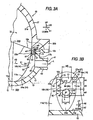
- the waterproof construction for preventing or suppressing the entering of water drops into the negative pressure outlet port 42 is made up of the recessed portion 50 and the projecting portion 60.
- the recessed portion 50 which is recessed in the horizontal direction A1, is provided on part of the inner surface 17a of the side wall 17 of the lower case 10.
- the recessed portion 50 has, in its deep portion, the deep surface 53 to which the negative pressure outlet port 42 opens, and the opening 51 opened upwards is provided in the upper portion of the recessed portion 50 in the position which opposes to the upper case 20 in the vertical direction A0.
- the upper case 20 has the projecting portion 60 which extends further downward towards the negative pressure outlet port 42 than the mating surfaces 10a, 20a and projects into the recessed portion 50 through the opening 52, and the projecting portion 60 is positioned above the negative pressure outlet port 42 and between the negative pressure outlet port 42 and the inner surface 17 in the horizontal direction A1.
- the lower end portion 63 of the projecting portion 60 is formed into the arc-like shape in which the central portion 65 in the horizontal direction A2 projects downwards. Accordingly, the water drops, which flow down towards the negative pressure outlet port 42 along the inner surface 27a of the side wall 27, flow down along the projecting portion 60 which lies closer to the merged passage 32 side than the negative pressure outlet port 42 to fall downwards from the lower end portion 63 of the projecting portion 60.
- the entering of water drops into the negative pressure outlet port 42 which lies deeper than the projecting portion 60 in the recessed portion 50 is suppressed. Accordingly, the reduction in performance of the function of taking-out the negative pressure can be prevented which would otherwise be caused by water drops which have entered from the negative pressure outlet port 42 become frozen. Further, since the projecting portion 60 is accommodated within the recessed portion 50 and hence does not project from the inner surface 17a into the merged passage 32, the increase in passage resistance in the merged passage 32 by the waterproof construction made up of the recessed portion 50 and the projecting portion 60 is suppressed, and the intake efficiency is increased by such an extent that the increase in passage resistance is so suppressed.
- the waterproof construction is configured by connecting to each other the lower case 10, which has the recessed portion 50 on which the negative pressure outlet port 42 and the opening 52 opened upwards are provided, and the upper case 20, which has the projecting portion 60 extending downwards, while accommodating the projecting portion 60 so as to project from the opening 52 into the recessed portion 52. Therefore, since the lower case 10 and the upper case 20 which have the recessed portion 50 and the projecting portion 60, respectively, are separate members, the respective constructions of the recessed portion 50 and the projecting portion 60 are simplified. Further, their easiness of molding process is increased including a case where the recessed portion 50 and the projecting portion 60 are molded integrally on the lower case 10 and the upper case 20, respectively. Therefore, the production costs of the intake device 1 can be reduced.
- the projecting portion 60 which is situated within the recessed portion 50 is positioned between the inner surface 17a and the negative pressure outlet port 42 in the horizontal direction A1 which is also the direction in which the recessed portion 50 is recessed relative to the inner surface of the lower case 10. Therefore, the projecting portion 60 is not required to surround the negative pressure outlet port 42. Accordingly, the recessed portion 50 is made smaller in size, which increases the degree of freedom in disposing the negative pressure outlet port 42, and the lower case 10 can be made smaller in size and lighter in weight. Since the negative pressure outlet port 42 opens to the deep surface 53, compared with a case where the negative pressure outlet port 42 opens to the depth surface 54 of the recessed portion 50, the recessed portion 50 can be made small in size in the horizontal direction A1.
- the projecting portion 60 is positioned above the negative pressure outlet port 42 and is not positioned further downwards than the negative pressure outlet port 42.
- the projecting portion 60 does not cover the negative pressure outlet port 42 in the horizontal direction A1 which is also the direction in which the recessed portion 50 is recessed relative to the inner surface 17a. Therefore, even if the projecting portion 60 and the negative pressure outlet port 42 are positioned closed to each other in the horizontal direction A1, a negative pressure is not prevented from taking-out from the negative pressure outlet port 42 by the projecting portion 60.
- the negative pressure taking-out function can be ensured while making the waterproof construction small in size in the horizontal direction A1.
- the length w5 of the projecting portion 60 can be made shorter than the width w6 so as to shorten the length w5 of the projecting portion 60 in the vertical direction A0, and the lower end portion 63 is formed into the arc-like shape in which the central portion 65 projects downwards. Therefore, the damage to the projecting portion 60, such as a case where the projecting portion 60 is broken which would otherwise occur when the upper case 20 is placed temporarily with its mating surface 20a oriented downwards before it is connected to the lower case 10, can be avoided.
- the projecting portion 60 situated within the recessed portion 50 extends downwards to cover the recessed portion 50, the turbulent flow of intake air caused by the recessed portion 50 is suppressed. Therefore, the increase in passage resistance in the intake passage due to the recessed portion 50 is suppressed further. Moreover, the adhesion of water drops to the recessed surface, which includes the deep surface 53 above the negative pressure outlet port, 42 is suppressed. Thus, the effect of preventing the entering of water drops into the negative pressure outlet port 42 is improved.
- the recessed surface of the recessed portion 50 has the deep surface 53 which opposes to the projecting portion 60 in the horizontal direction A1, and the negative pressure outlet port 42 opens to the deep surface 53.
- the gap 71 provided between the deep surface 53 and the projecting portion 60 in the horizontal direction water drops falling along the projecting portion 60 are prevented from continuing to fall from the lower end portion 63 of the projecting portion 60 to the deep surface 53 opened to the negative pressure outlet port 42 by the gap 71 provided between the projecting portion 60 and the deep surface 53 in the horizontal direction A1. Consequently, the entering of water drops into the negative pressure outlet port 42 can be suppressed further.
- the effect of preventing the entering of water drops into the negative pressure outlet port 42 by the waterproof construction is improved.
- passage components other than an intake manifold 4 which makes up an intake passage may be made up of a plurality of passage walls which include at least a lower passage wall and an upper passage wall, and a recessed portion, a projecting portion and a negative pressure outlet portion 42 may be provided in the passage components.
- a recessed portion 50 or a projecting portion 60 may be a separate member from a side wall 17 of a lower case 10 or a side wall 27 of an upper case 20 and may be made up of a passage wall which is may be attached and/or detached to the side walls 17, 27.
- a negative pressure outlet portion 40 may be a separate member from the recessed portion 50.
- a gap 71 may be formed so that a rear surface 62 of a projecting portion 60 and a deep surface 53 are in contact with each other via a projecting portion which is provided on the rear surface 62 or the deep surface 53.
- the rear surface 62 and the deep surface 53 may be in surface contact with each other over substantially the whole area thereof.
- the shape of the negative pressure outlet port 42 may take other shapes than the circular shape. In the embodiments, while the negative pressure outlet port 42 opens only to the deep surface 53, the negative pressure outlet port 42 may also open to a range between the deep surface 53 and the depth surface 54 or only to the depth surface 54.
- the throttle device 3 is a carburetor.
- the intake manifold 4 which is other than the merged portion 4b such as the branch portion 4c or the passage components which makes up the intake device 1 and is other than the intake manifold 4 (for example, the throttle body 3b of the throttle device 3) may include an upper passage wall having a recessed portion 50 and an upper passage wall having a projecting portion 60.
- the internal combustion engine may be a compression ignition type internal combustion engine or an internal combustion engine that is used for a marine propulsion system such as a marine outboard engine which includes a crankshaft directed in a vertical direction A0.
- An intake passage is formed by connecting upper and lower cases 10, 20 of an intake manifold.
- the lower case 10 has a recessed portion 50 on an inner surface 17a.
- the recessed portion 50 has a deep surface 53 to which a negative pressure outlet port 42 opens, and an opening 51 is provided in an upper portion of the recessed portion 50.
- the upper case 20 has a projecting portion 60 extending further downwards towards the negative pressure outlet port 42 than mating surfaces 10a, 20a and projects into the recessed portion 50 through an opening 52.
- the projecting portion 60 is positioned above the negative pressure outlet port 42 and between the negative pressure outlet port 42 and the inner surface 17a.
- a lower end portion 63 of the projecting portion 60 is formed into an arc-like shape of which central portion 65 projects downwards.
Landscapes
- Engineering & Computer Science (AREA)
- Chemical & Material Sciences (AREA)
- Combustion & Propulsion (AREA)
- Mechanical Engineering (AREA)
- General Engineering & Computer Science (AREA)
- Manufacturing & Machinery (AREA)
- Control Of Throttle Valves Provided In The Intake System Or In The Exhaust System (AREA)
Claims (2)
- Dispositif d'admission (1) d'un moteur à combustion interne, comprenant :une paroi de passage supérieure (20) et une paroi de passage inférieure (10) qui sont disposées l'une à côté de l'autre dans une direction verticale et sont raccordées ensemble afin de former un passage d'admission, dans lequel :la paroi de passage inférieure (10) a une partie évidée (50), qui est évidée dans une direction horizontale, dans une partie de sa surface interne,dans une partie profonde dans la direction horizontale, la partie évidée (50) a une surface évidée dans laquelle s'ouvre un orifice de sortie de pression négative (42) pour retirer la pression négative générée dans le passage d'admission,une ouverture (52) qui s'ouvre vers le haut, est prévue dans une position qui s'oppose à la paroi de passage supérieure dans la direction verticale au niveau d'une partie supérieure de la partie évidée,la paroi de passage supérieure (20) a une partie en saillie (60) qui s'étend davantage vers le bas qu'une surface de couplage située entre la paroi de passage supérieure (20) et la paroi de passage inférieure (10) et qui fait saillie dans la partie évidée à travers l'ouverture,la partie en saillie (60) est positionnée au-dessus de l'orifice de sortie de pression négative (42) et entre l'orifice de sortie de pression négative (42) et la surface interne dans la direction horizontale, etune partie d'extrémité inférieure (63) de la partie en saillie est formée selon une forme d'arc dans laquelle une partie centrale dans une direction qui est perpendiculaire à la direction horizontale, lorsqu'elle est observée à partir d'une direction verticale, fait saillie vers le bas.
- Dispositif d'admission du moteur à combustion interne selon la revendication 1, dans lequel :la surface évidée (54) a une surface profonde qui s'oppose à la partie en saillie dans la direction horizontale,l'orifice de sortie de pression négative (40) s'ouvre sur la surface profonde, etun espace (71) est prévu dans la direction horizontale entre la surface profonde et la partie en saillie.
Applications Claiming Priority (1)
| Application Number | Priority Date | Filing Date | Title |
|---|---|---|---|
| JP2007186039A JP4823159B2 (ja) | 2007-07-17 | 2007-07-17 | 内燃機関の吸気装置 |
Publications (2)
| Publication Number | Publication Date |
|---|---|
| EP2017460A1 EP2017460A1 (fr) | 2009-01-21 |
| EP2017460B1 true EP2017460B1 (fr) | 2011-06-15 |
Family
ID=39926645
Family Applications (1)
| Application Number | Title | Priority Date | Filing Date |
|---|---|---|---|
| EP08012945A Ceased EP2017460B1 (fr) | 2007-07-17 | 2008-07-17 | Dispositif d'admission de moteur à combustion interne |
Country Status (4)
| Country | Link |
|---|---|
| US (1) | US7895984B2 (fr) |
| EP (1) | EP2017460B1 (fr) |
| JP (1) | JP4823159B2 (fr) |
| CN (1) | CN101349227B (fr) |
Family Cites Families (15)
| Publication number | Priority date | Publication date | Assignee | Title |
|---|---|---|---|---|
| US1616247A (en) * | 1925-09-11 | 1927-02-01 | Leonard E Aske | Electric heater or vaporizer |
| US4715348A (en) * | 1985-08-31 | 1987-12-29 | Nippondenso Co., Ltd. | Self-diagnosis system for exhaust gas recirculation system of internal combustion engine |
| JPH11141417A (ja) * | 1997-11-06 | 1999-05-25 | Toyota Motor Corp | サージタンク |
| JP2000088688A (ja) * | 1998-09-11 | 2000-03-31 | Nippon Soken Inc | 内燃機関の圧力検出装置 |
| JP3505431B2 (ja) | 1999-05-12 | 2004-03-08 | 小島プレス工業株式会社 | Vsv用ポートの水入り防止構造 |
| CN1362578A (zh) * | 2001-12-27 | 2002-08-07 | 干方飞 | 真空负压式可变长度的内燃机进气系统 |
| JP2003254179A (ja) | 2002-02-26 | 2003-09-10 | Denso Corp | インテークマニホールド |
| JP4088505B2 (ja) * | 2002-10-03 | 2008-05-21 | トヨタ自動車株式会社 | 内燃機関吸気系の吸気負圧取り出し部の水入り防止構造 |
| CA2470599C (fr) * | 2003-06-13 | 2010-08-03 | Honda Motor Co., Ltd. | Dispositif d'admission a double orifice pour moteur a combustion , forme par moulage par injection |
| JP4357233B2 (ja) | 2003-07-31 | 2009-11-04 | トヨタ自動車株式会社 | 内燃機関のサージタンク |
| US6971358B2 (en) * | 2004-04-22 | 2005-12-06 | Keihin Corporation | Intake system for internal combustion engine and method of controlling internal combustion engine |
| US7036493B1 (en) * | 2004-10-08 | 2006-05-02 | General Motors Corporation | Intake manifold for an internal combustion engine |
| JP4422654B2 (ja) * | 2005-08-02 | 2010-02-24 | トヨタ自動車株式会社 | インテークマニホルド |
| JP4928135B2 (ja) * | 2006-02-27 | 2012-05-09 | 株式会社マーレ フィルターシステムズ | 内燃機関の吸気装置および吸気マニホルド |
| JP4814164B2 (ja) * | 2007-07-17 | 2011-11-16 | 本田技研工業株式会社 | 内燃機関の吸気装置 |
-
2007
- 2007-07-17 JP JP2007186039A patent/JP4823159B2/ja not_active Expired - Fee Related
-
2008
- 2008-07-16 US US12/174,423 patent/US7895984B2/en active Active
- 2008-07-17 EP EP08012945A patent/EP2017460B1/fr not_active Ceased
- 2008-07-17 CN CN2008101315643A patent/CN101349227B/zh active Active
Also Published As
| Publication number | Publication date |
|---|---|
| CN101349227A (zh) | 2009-01-21 |
| JP4823159B2 (ja) | 2011-11-24 |
| EP2017460A1 (fr) | 2009-01-21 |
| JP2009024523A (ja) | 2009-02-05 |
| US20090020096A1 (en) | 2009-01-22 |
| US7895984B2 (en) | 2011-03-01 |
| CN101349227B (zh) | 2011-07-20 |
Similar Documents
| Publication | Publication Date | Title |
|---|---|---|
| JP4422654B2 (ja) | インテークマニホルド | |
| EP2017461B1 (fr) | Dispositif d'admission de moteur à combustion interne | |
| JP4722800B2 (ja) | レゾネータを備える多気筒内燃機関 | |
| JP2009203966A (ja) | 内燃機関の吸気装置 | |
| US6622682B2 (en) | Sealing arrangement for an intake manifold of an internal combustion engine | |
| EP2123896B1 (fr) | Collecteur d'admission pour moteur à combustion interne à plusieurs cylindres | |
| JP4305828B2 (ja) | 内燃機関の吸気マニホールド | |
| KR101129918B1 (ko) | 다기통 내연기관의 흡기 매니폴드 | |
| EP2017460B1 (fr) | Dispositif d'admission de moteur à combustion interne | |
| JP7605188B2 (ja) | インテークマニホールド | |
| US11635050B2 (en) | Intake manifold and outboard motor | |
| CN220395794U (zh) | 全地形车 | |
| JP4960944B2 (ja) | 内燃機関の吸気装置 | |
| CN220487745U (zh) | 全地形车 | |
| JP2002256991A (ja) | インテークマニホールドの負圧取出し構造 | |
| JP7371534B2 (ja) | エンジンにおけるブローバイガス還流構造 | |
| JP5416534B2 (ja) | 内燃機関の排気ガス還流装置 | |
| JP4257638B2 (ja) | 樹脂製吸気マニホルド | |
| JP2003314327A (ja) | 吸気通路の圧力検出装置 | |
| JP4478602B2 (ja) | エンジン | |
| CN119222074A (zh) | 全地形车 | |
| TH40422A3 (th) | ช่องทางการจ่ายอากาศทุติยภูมิสำหรับเครื่องยนต์ |
Legal Events
| Date | Code | Title | Description |
|---|---|---|---|
| PUAI | Public reference made under article 153(3) epc to a published international application that has entered the european phase |
Free format text: ORIGINAL CODE: 0009012 |
|
| 17P | Request for examination filed |
Effective date: 20080717 |
|
| AK | Designated contracting states |
Kind code of ref document: A1 Designated state(s): AT BE BG CH CY CZ DE DK EE ES FI FR GB GR HR HU IE IS IT LI LT LU LV MC MT NL NO PL PT RO SE SI SK TR |
|
| AX | Request for extension of the european patent |
Extension state: AL BA MK RS |
|
| AKX | Designation fees paid |
Designated state(s): DE GB |
|
| GRAP | Despatch of communication of intention to grant a patent |
Free format text: ORIGINAL CODE: EPIDOSNIGR1 |
|
| GRAS | Grant fee paid |
Free format text: ORIGINAL CODE: EPIDOSNIGR3 |
|
| RAP1 | Party data changed (applicant data changed or rights of an application transferred) |
Owner name: KEIHIN CORPORATION Owner name: HONDA MOTOR CO., LTD. |
|
| GRAA | (expected) grant |
Free format text: ORIGINAL CODE: 0009210 |
|
| AK | Designated contracting states |
Kind code of ref document: B1 Designated state(s): DE GB |
|
| REG | Reference to a national code |
Ref country code: GB Ref legal event code: FG4D |
|
| REG | Reference to a national code |
Ref country code: DE Ref legal event code: R096 Ref document number: 602008007541 Country of ref document: DE Effective date: 20110804 |
|
| PLBE | No opposition filed within time limit |
Free format text: ORIGINAL CODE: 0009261 |
|
| STAA | Information on the status of an ep patent application or granted ep patent |
Free format text: STATUS: NO OPPOSITION FILED WITHIN TIME LIMIT |
|
| 26N | No opposition filed |
Effective date: 20120316 |
|
| REG | Reference to a national code |
Ref country code: DE Ref legal event code: R097 Ref document number: 602008007541 Country of ref document: DE Effective date: 20120316 |
|
| GBPC | Gb: european patent ceased through non-payment of renewal fee |
Effective date: 20120717 |
|
| PG25 | Lapsed in a contracting state [announced via postgrant information from national office to epo] |
Ref country code: GB Free format text: LAPSE BECAUSE OF NON-PAYMENT OF DUE FEES Effective date: 20120717 |
|
| PGFP | Annual fee paid to national office [announced via postgrant information from national office to epo] |
Ref country code: DE Payment date: 20200707 Year of fee payment: 13 |
|
| REG | Reference to a national code |
Ref country code: DE Ref legal event code: R119 Ref document number: 602008007541 Country of ref document: DE |
|
| PG25 | Lapsed in a contracting state [announced via postgrant information from national office to epo] |
Ref country code: DE Free format text: LAPSE BECAUSE OF NON-PAYMENT OF DUE FEES Effective date: 20220201 |