EP2017462A1 - Procédé et appareil pour nettoyer une ligne de fluide - Google Patents
Procédé et appareil pour nettoyer une ligne de fluide Download PDFInfo
- Publication number
- EP2017462A1 EP2017462A1 EP07110767A EP07110767A EP2017462A1 EP 2017462 A1 EP2017462 A1 EP 2017462A1 EP 07110767 A EP07110767 A EP 07110767A EP 07110767 A EP07110767 A EP 07110767A EP 2017462 A1 EP2017462 A1 EP 2017462A1
- Authority
- EP
- European Patent Office
- Prior art keywords
- bypass
- fuel
- closure element
- filter element
- medium line
- Prior art date
- Legal status (The legal status is an assumption and is not a legal conclusion. Google has not performed a legal analysis and makes no representation as to the accuracy of the status listed.)
- Granted
Links
- 238000004140 cleaning Methods 0.000 title claims abstract description 16
- 238000000034 method Methods 0.000 title claims abstract description 15
- 239000012530 fluid Substances 0.000 title description 2
- 239000000446 fuel Substances 0.000 claims abstract description 76
- 238000002485 combustion reaction Methods 0.000 claims abstract description 20
- 238000001914 filtration Methods 0.000 claims abstract description 9
- 230000009849 deactivation Effects 0.000 claims description 3
- 238000004519 manufacturing process Methods 0.000 description 20
- 239000012535 impurity Substances 0.000 description 5
- KFZMGEQAYNKOFK-UHFFFAOYSA-N Isopropanol Chemical compound CC(C)O KFZMGEQAYNKOFK-UHFFFAOYSA-N 0.000 description 4
- 238000009434 installation Methods 0.000 description 4
- 239000000356 contaminant Substances 0.000 description 3
- 239000002828 fuel tank Substances 0.000 description 3
- 230000032258 transport Effects 0.000 description 3
- 230000006835 compression Effects 0.000 description 1
- 238000007906 compression Methods 0.000 description 1
- 238000011109 contamination Methods 0.000 description 1
- 230000000694 effects Effects 0.000 description 1
- 230000002349 favourable effect Effects 0.000 description 1
- 239000007788 liquid Substances 0.000 description 1
- 238000010926 purge Methods 0.000 description 1
- 238000007789 sealing Methods 0.000 description 1
Images


Classifications
-
- F—MECHANICAL ENGINEERING; LIGHTING; HEATING; WEAPONS; BLASTING
- F02—COMBUSTION ENGINES; HOT-GAS OR COMBUSTION-PRODUCT ENGINE PLANTS
- F02M—SUPPLYING COMBUSTION ENGINES IN GENERAL WITH COMBUSTIBLE MIXTURES OR CONSTITUENTS THEREOF
- F02M37/00—Apparatus or systems for feeding liquid fuel from storage containers to carburettors or fuel-injection apparatus; Arrangements for purifying liquid fuel specially adapted for, or arranged on, internal-combustion engines
- F02M37/22—Arrangements for purifying liquid fuel specially adapted for, or arranged on, internal-combustion engines, e.g. arrangements in the feeding system
- F02M37/32—Arrangements for purifying liquid fuel specially adapted for, or arranged on, internal-combustion engines, e.g. arrangements in the feeding system characterised by filters or filter arrangements
- F02M37/36—Arrangements for purifying liquid fuel specially adapted for, or arranged on, internal-combustion engines, e.g. arrangements in the feeding system characterised by filters or filter arrangements with bypass means
-
- F—MECHANICAL ENGINEERING; LIGHTING; HEATING; WEAPONS; BLASTING
- F02—COMBUSTION ENGINES; HOT-GAS OR COMBUSTION-PRODUCT ENGINE PLANTS
- F02M—SUPPLYING COMBUSTION ENGINES IN GENERAL WITH COMBUSTIBLE MIXTURES OR CONSTITUENTS THEREOF
- F02M37/00—Apparatus or systems for feeding liquid fuel from storage containers to carburettors or fuel-injection apparatus; Arrangements for purifying liquid fuel specially adapted for, or arranged on, internal-combustion engines
- F02M37/0011—Constructional details; Manufacturing or assembly of elements of fuel systems; Materials therefor
- F02M37/0017—Constructional details; Manufacturing or assembly of elements of fuel systems; Materials therefor related to fuel pipes or their connections, e.g. joints or sealings
-
- F—MECHANICAL ENGINEERING; LIGHTING; HEATING; WEAPONS; BLASTING
- F02—COMBUSTION ENGINES; HOT-GAS OR COMBUSTION-PRODUCT ENGINE PLANTS
- F02M—SUPPLYING COMBUSTION ENGINES IN GENERAL WITH COMBUSTIBLE MIXTURES OR CONSTITUENTS THEREOF
- F02M37/00—Apparatus or systems for feeding liquid fuel from storage containers to carburettors or fuel-injection apparatus; Arrangements for purifying liquid fuel specially adapted for, or arranged on, internal-combustion engines
- F02M37/0011—Constructional details; Manufacturing or assembly of elements of fuel systems; Materials therefor
- F02M37/0023—Valves in the fuel supply and return system
- F02M37/0035—Thermo sensitive valves
-
- F—MECHANICAL ENGINEERING; LIGHTING; HEATING; WEAPONS; BLASTING
- F02—COMBUSTION ENGINES; HOT-GAS OR COMBUSTION-PRODUCT ENGINE PLANTS
- F02M—SUPPLYING COMBUSTION ENGINES IN GENERAL WITH COMBUSTIBLE MIXTURES OR CONSTITUENTS THEREOF
- F02M37/00—Apparatus or systems for feeding liquid fuel from storage containers to carburettors or fuel-injection apparatus; Arrangements for purifying liquid fuel specially adapted for, or arranged on, internal-combustion engines
- F02M37/22—Arrangements for purifying liquid fuel specially adapted for, or arranged on, internal-combustion engines, e.g. arrangements in the feeding system
- F02M37/32—Arrangements for purifying liquid fuel specially adapted for, or arranged on, internal-combustion engines, e.g. arrangements in the feeding system characterised by filters or filter arrangements
- F02M37/34—Arrangements for purifying liquid fuel specially adapted for, or arranged on, internal-combustion engines, e.g. arrangements in the feeding system characterised by filters or filter arrangements by the filter structure, e.g. honeycomb, mesh or fibrous
Definitions
- the invention relates to a method for cleaning at least a portion of a medium line of an internal combustion engine.
- the invention also relates to a device for carrying out the method.
- Medium lines such as or fuel lines of an internal combustion engine are production-related often manufacturing residues, such as chips or the like.
- the medium lines or the low-pressure side of the high-pressure pump fuel lines are flushed before their installation on the internal combustion engine by means of a cleaning liquid and cleaned.
- Isopropanol is currently used as cleaning fluid. This purging is required for all the vacuum side fuel lines which are arranged between the main filter and the high pressure pump.
- the known cleaning method depending on the number and length of the fuel line, very expensive and must be performed to avoid additional contamination in a special clean room.
- the transport of the medium lines or fuel lines to and from the clean room increases the cost in addition.
- the invention has the object to improve a method and an apparatus of the type mentioned above so that the aforementioned disadvantages are repealed.
- the invention is based on the idea that when starting an internal combustion engine, the passage of a fuel through a medium line any impurities and / or contaminants removed from this medium line. Subsequent filtering prevents impurities / contaminants from being carried on with the fuel. The medium line is cleaned in this way. After some time / duration of operation, the filtering can be deactivated, since then usually all impurities / contaminants are washed out of the medium line.
- the fuel such as fuel such. B. diesel
- the filter element By means of the bypass according to the invention, the fuel, such as fuel such. B. diesel, which entrains the impurities in the at least one portion of the medium line and transported through the bypass to the filter element, filtered so that z. B. manufacturing residues z. B. can not get into a high-pressure pump, but are collected by the filter element.
- the at least one section of the medium line, preferably the fuel or diesel line from the fuel tank to the high pressure pump can be sufficiently cleaned of the manufacturing residues, without the costly cleaning measures must be performed in clean rooms.
- the life of the high-pressure pump according to the known cleaning with cleaning media such. B. Isopropanol is secured.
- the cleaning process is preferably carried out by the manufacturer.
- fuel z. B. diesel from a central tank filled in the fuel tank of the motor vehicle.
- the fuel or diesel has a relatively low temperature of about 20 ° C.
- the fuel heats up to a higher temperature, for example 80 ° C., due to friction and the compression of the fuel in a fuel pump.
- This effect is advantageously exploited by using a thermovalve responsive to the temperature change as the closure element.
- the closure member or thermal valve remains in a bypass opening position (use position).
- the bypass is opened after the first start of the internal combustion engine, and shut off the vacuum-side input to the high-pressure pump.
- the fuel is forced to flow through the bypass and transport the entrained production residues to the filter element, in which they are collected.
- the fuel is subject to a suction pressure generated by the internal combustion engine and flows at a flow rate of, for example, 120 l / h. If the fuel or diesel reaches the operating temperature of the closure element or of the thermal valve after a sufficient time, the bypass is closed and the vacuum-side inlet to the high-pressure pump is opened.
- the bypass remains permanently closed, so that the fuel can flow through the bypass or through the filter element into the high-pressure pump.
- the filter element is permanently bypassed by the bypass is permanently closed.
- the closure element or the thermal valve is designed such that it keeps the bypass closed even at a temperature below its operating temperature, so no longer opens after the one-time closing.
- the exemplary (vacuum side) fuel line can be installed or mounted on the internal combustion engine, and be cleaned with the inventive method in the installed on the engine position of the manufacturing residues, without cleaning before installation is necessary.
- the object is also achieved by a device for cleaning at least a portion of a medium line of an internal combustion engine with the features of claim 5.
- the medium line or fuel line is a closable by means of a closure element bypass, in which a filter element is arranged, assigned such that fuel from the at least a portion of the medium line after a first start of the engine flows through the bypass, the bypass permanently closed is when the at least a portion of the medium line is cleaned.
- the closure element is expediently designed as a thermal valve, wherein the bypass in the flow direction of the fuel or fuel z.
- B. Diesel for example, between the actual fuel filter and the internal combustion engine, preferably a high-pressure pump is arranged immediately.
- the high pressure pump has a negative pressure side and a positive pressure side.
- Overpressure-side fuel lines or the high-pressure pump itself are cleaned of manufacturing residues prior to installation on the internal combustion engine.
- vacuum-side fuel lines can be cleaned with the proposed device and the method according to the invention.
- the bypass is therefore arranged with its input side on the negative pressure side and with its output branch on the overpressure side, so that the high-pressure pump is bypassed.
- the closure element is arranged on the input side of the bypass. It is also possible that the closure element is arranged in a flow channel between the input side and the corresponding output port in the medium line.
- the filter element is expediently arranged between the closure element and the outlet port in the bypass, that is, as seen in the flow direction of the fuel or fuel expedient behind the closure element. It is also possible to provide a flap element in front of the exit orifice, preferably a non-return flap, in order to avoid that the bypass is opened in the event of an unexpected failure of the closure element.
- the filter element is designed in a preferred embodiment as a so-called disk filter, which holds the manufacturing residues in the flow direction.
- the filter element is not limited to this embodiment, but can be selected in any suitable embodiment, provided that the manufacturing residues can be sufficiently collected and recorded.
- the filter element should not replace the actual fuel filter, which is to filter impurities of the fuel or diesel; Because the bypass is open only temporarily after a first start of the engine until the fuel has reached the operating temperature of the closure element and then permanently closed. This can, however, be carried out a cleaning, for example, based on the high pressure pump vacuum side fuel line after installation on the engine.
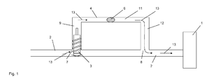
- FIG. 1 shows in principle an internal combustion engine 1 with a medium line 2.
- the medium line 2 is designed as a fuel line, and is hereinafter referred to as such.
- the fuel line 2 has a closable by means of a closure element 3 by-pass 4.
- a filter element 6 is arranged in the bypass 4.
- fuel such as diesel
- the fuel line 2 takes on manufacturing residues (chips or the like) and transports them through the bypass 4 to the filter element 6.
- manufacturing residues are collected and permanently detained.
- the bypass 4 is executed in the illustrated embodiment in longitudinal section seen U-shaped.
- the bypass 4 has an input side 7 and a corresponding output port 8 connected to the fuel line 2.
- the bypass 4 runs on the input side with its input branch 9 initially oriented perpendicularly away from the fuel line 2, and merges into a parallel to the fuel line 2 flow section 11.
- the flow section 11 merges into an outlet branch 12, which is oriented in the direction of the fuel line 2 and opens with its outlet opening 8 in this.
- the bypass 4 may be implemented in any other suitable embodiment.
- the bypass 4 could be seen in longitudinal section cut horseshoe-shaped with a curved flow section.
- the closure element 3 is arranged on the input side. In the in FIG. 1 shown position, the closure element 3 is in a bypass 4 opening position (use position), so that fuel, for example diesel flows through the bypass 4 and the filter element 6 in the direction of the outlet port 8. The flow direction is shown by the arrows 13.
- the filter element 6 is arranged in the flow direction of the fuel (arrow 13) behind the closure element 3.
- FIG. 1 is exemplified a common rail line of a diesel engine with a high-pressure pump, not shown.
- the high pressure pump not shown, has a negative pressure side and a positive pressure side.
- the bypass 4 is arranged so that the input side 7 on the vacuum side and the output port. 8 is arranged on the pressure side.
- the bypass 4 bypasses the high-pressure pump. This is favorable for the purposes of the invention, since the overpressure-side fuel line (as seen from the high pressure pump) and the high-pressure pump itself are already cleaned of manufacturing residues.
- the filter element 6 so the production residues of at least a portion of the fuel line, preferably the vacuum-side fuel line are collected, without that they can get into the high-pressure pump.
- the fuel for example diesel is filled from a central tank in the fuel tank of the motor vehicle and has a relatively low temperature of about 20 ° C.
- the filter element 6 catches the manufacturing residues, so that the vacuum side fuel line is cleaned of them .
- the closure element 3 is therefore advantageously designed as a thermal valve, which permanently closes the bypass 4, for example, at 70 ° C fuel temperature.
- the fuel z. B.
- the bypass 4 remains permanently closed. This condition is in FIG. 2 shown.
- the closure element 3 in the preferred embodiment as a thermal valve is designed such that it no longer opens after closing the bypass 4, or keeps the bypass 4 permanently closed. In this respect, it is also possible to speak of a temporary bypass 4 or filter element 6, the only function of which is to be seen in the cleaning of the vacuum-side fuel line; because after the fuel line is cleaned of the manufacturing residues, the bypass 4 remains permanently closed.
- the closure element 3 has a sealing device 14 on the foot side, which bears sealingly against the upper inner wall 16 of the fuel line 2 in the plane of the drawing ( FIG. 2 ).
- a flap element 17, for example, a non-return valve is arranged in the output branch 12 in the output branch 12.
- the flap element 17 is arranged in a position permanently closing the output branch 12 when the bypass 4 is permanently closed by means of the closure element 3 or the thermo-valve.
- the flap member 17 prevents inflow into the bypass 4, in the event that the closure element 3, the bypass 4 should open unexpectedly.
- the flap element 17 serves as a kind of second closure element or as a securing element. Conveniently, the flap member 17 is permanently fixed in the output branch 12 closing position, for example, locked.
- closure element 3 is arranged in the flow channel 11, wherein the filter element 6 is arranged in the output branch 12.
- the closure element 3 closes the bypass 4 and simultaneously opens the entrance to the high-pressure pump.
- the flap member 17 can of course also in the embodiment according to FIG. 3 be provided.
- the respective closure element 3 in the FIGS. 1 to 3 should be shown only by way of example, this should be carried out in each case so that on the one hand, a closing of the input side of the high-pressure pump and on the other a permanent closing of the bypass 4 is possible.
Landscapes
- Engineering & Computer Science (AREA)
- Chemical & Material Sciences (AREA)
- Combustion & Propulsion (AREA)
- Mechanical Engineering (AREA)
- General Engineering & Computer Science (AREA)
- Fuel-Injection Apparatus (AREA)
Priority Applications (2)
| Application Number | Priority Date | Filing Date | Title |
|---|---|---|---|
| DE502007004018T DE502007004018D1 (de) | 2007-06-21 | 2007-06-21 | Verfahren und Vorrichtung zum Reinigen einer Mediumleitung |
| EP07110767A EP2017462B1 (fr) | 2007-06-21 | 2007-06-21 | Procédé et appareil pour nettoyer une ligne de fluide |
Applications Claiming Priority (1)
| Application Number | Priority Date | Filing Date | Title |
|---|---|---|---|
| EP07110767A EP2017462B1 (fr) | 2007-06-21 | 2007-06-21 | Procédé et appareil pour nettoyer une ligne de fluide |
Publications (2)
| Publication Number | Publication Date |
|---|---|
| EP2017462A1 true EP2017462A1 (fr) | 2009-01-21 |
| EP2017462B1 EP2017462B1 (fr) | 2010-06-02 |
Family
ID=38670803
Family Applications (1)
| Application Number | Title | Priority Date | Filing Date |
|---|---|---|---|
| EP07110767A Ceased EP2017462B1 (fr) | 2007-06-21 | 2007-06-21 | Procédé et appareil pour nettoyer une ligne de fluide |
Country Status (2)
| Country | Link |
|---|---|
| EP (1) | EP2017462B1 (fr) |
| DE (1) | DE502007004018D1 (fr) |
Cited By (2)
| Publication number | Priority date | Publication date | Assignee | Title |
|---|---|---|---|---|
| EP2009275A1 (fr) * | 2007-06-23 | 2008-12-31 | Careng automotive GmbH | Filtre et procédé de filtration d'un liquide |
| EP2886844A1 (fr) * | 2013-12-17 | 2015-06-24 | TI Automotive (Heidelberg) GmbH | Module de conduite de carburant et procédé de fonctionnement d'un module de conduite de carburant |
Citations (7)
| Publication number | Priority date | Publication date | Assignee | Title |
|---|---|---|---|---|
| DE3631579C1 (de) * | 1986-09-17 | 1992-02-20 | Daimler Benz Ag | Niederdruckkraftstoffkreislauf mit Kraftstoffvorwaermung fuer eine luftverdichtende Einspritzbrennkraftmaschine,insbesondere fuer Nutzfahrzeuge |
| EP1136689A2 (fr) | 2000-03-21 | 2001-09-26 | Mannesmann VDO Aktiengesellschaft | Dispositif d'alimentation en carburant |
| WO2002014680A1 (fr) * | 2000-08-11 | 2002-02-21 | Siemens Aktiengesellschaft | Dispositif filtrant destine a une zone haute pression du systeme d'injection d'un reservoir de stockage destine a un moteur a combustion interne |
| WO2004020816A1 (fr) | 2002-08-28 | 2004-03-11 | Robert Bosch Gmbh | Dispositif d'injection de carburant pour moteur a combustion interne |
| EP1475534A2 (fr) | 2003-04-11 | 2004-11-10 | Mann+Hummel Gmbh | Véhicule automobile avec moteur à combustion interne fonctionnant à carburant diesel |
| WO2007031120A1 (fr) | 2005-05-18 | 2007-03-22 | Schaeffler Kg | Soupape de pression pour dispositif d'injection de carburant d'un moteur a combustion interne |
| EP1826393A1 (fr) | 2006-02-22 | 2007-08-29 | Mann+Hummel Gmbh | Système de filtration pour liquides |
-
2007
- 2007-06-21 EP EP07110767A patent/EP2017462B1/fr not_active Ceased
- 2007-06-21 DE DE502007004018T patent/DE502007004018D1/de active Active
Patent Citations (7)
| Publication number | Priority date | Publication date | Assignee | Title |
|---|---|---|---|---|
| DE3631579C1 (de) * | 1986-09-17 | 1992-02-20 | Daimler Benz Ag | Niederdruckkraftstoffkreislauf mit Kraftstoffvorwaermung fuer eine luftverdichtende Einspritzbrennkraftmaschine,insbesondere fuer Nutzfahrzeuge |
| EP1136689A2 (fr) | 2000-03-21 | 2001-09-26 | Mannesmann VDO Aktiengesellschaft | Dispositif d'alimentation en carburant |
| WO2002014680A1 (fr) * | 2000-08-11 | 2002-02-21 | Siemens Aktiengesellschaft | Dispositif filtrant destine a une zone haute pression du systeme d'injection d'un reservoir de stockage destine a un moteur a combustion interne |
| WO2004020816A1 (fr) | 2002-08-28 | 2004-03-11 | Robert Bosch Gmbh | Dispositif d'injection de carburant pour moteur a combustion interne |
| EP1475534A2 (fr) | 2003-04-11 | 2004-11-10 | Mann+Hummel Gmbh | Véhicule automobile avec moteur à combustion interne fonctionnant à carburant diesel |
| WO2007031120A1 (fr) | 2005-05-18 | 2007-03-22 | Schaeffler Kg | Soupape de pression pour dispositif d'injection de carburant d'un moteur a combustion interne |
| EP1826393A1 (fr) | 2006-02-22 | 2007-08-29 | Mann+Hummel Gmbh | Système de filtration pour liquides |
Cited By (2)
| Publication number | Priority date | Publication date | Assignee | Title |
|---|---|---|---|---|
| EP2009275A1 (fr) * | 2007-06-23 | 2008-12-31 | Careng automotive GmbH | Filtre et procédé de filtration d'un liquide |
| EP2886844A1 (fr) * | 2013-12-17 | 2015-06-24 | TI Automotive (Heidelberg) GmbH | Module de conduite de carburant et procédé de fonctionnement d'un module de conduite de carburant |
Also Published As
| Publication number | Publication date |
|---|---|
| DE502007004018D1 (de) | 2010-07-15 |
| EP2017462B1 (fr) | 2010-06-02 |
Similar Documents
| Publication | Publication Date | Title |
|---|---|---|
| EP2039893B1 (fr) | Dispositif et procédé de nettoyage de lubrifiants et circuit de lubrifiants | |
| EP2052660B1 (fr) | Appareil d'aspiration | |
| DE102010047354B3 (de) | Kraftstofffiltersystem eines Kraftstoffsystems einer Brennkraftmaschine und Verfahren zur Abscheidung von Wasser aus Kraftstoff | |
| EP3095995B1 (fr) | Refroidisseur d'air de suralimentation | |
| EP2435160B1 (fr) | Procédé de traitement d'air comprimé, dispositif de traitement d'air comprimé et véhicule automobile équipé dudit dispositif | |
| DE102008038026A1 (de) | Verfahren zum Reinigen eines Partikelfilters eines Kraftfahrzeugs | |
| DE102016216235B4 (de) | Vorrichtung zur wassereinspritzung in einem fahrzeug sowie verfahren zum betrieb einer solchen vorrichtung | |
| DE102017203796B4 (de) | Flüssigkeitsfilter mit einem Verdrängungskörper und Filterkartusche mit einem Verdrängungskörper | |
| EP1648583B1 (fr) | Ensemble filtre a huile et element filtrant | |
| EP3197581B1 (fr) | Element de filtre, filtre et system de filtre avec dérivation de retour | |
| WO2018234182A1 (fr) | Système de filtration à élément filtrant et élément secondaire pour fermer un tube médian | |
| DE69100220T2 (de) | Verfahren und Vorrichtung zum Filtrieren einer Flüssigkeit. | |
| EP2017462B1 (fr) | Procédé et appareil pour nettoyer une ligne de fluide | |
| DE102017214150A1 (de) | Kraftstoffeinspritzsystem und Versorgungsanordnung | |
| DE102011012031A1 (de) | Druckluftaufbereitungsanlage und Verfahren zur Herstellung einer Druckluftaufbereitungsanlage | |
| DE102010029600A1 (de) | Dosiersystem zum Eindosieren eines Reduktionsmittels in den Abgasstrang eines Kraftfahrzeuges | |
| DE102009030500A1 (de) | Flüssigkeitsfiltersystem eines Flüssigkeitskreislaufs | |
| DE102012017059A1 (de) | Filteranordnung zur Ölfiltration und Verfahren zum Betreiben derselben | |
| EP3371021B1 (fr) | Dispositif de préparation d'air comprimé et procédé pour faire fonctionner un tel dispositif | |
| DE102016212591A1 (de) | Flüssigfiltereinrichtung | |
| DE102015007059A1 (de) | Vorrichtung zum Überprüfen der Dichtheit eines Tanks, insbesondere für ein Kraftfahrzeug | |
| EP2716344A2 (fr) | Procédé et dispositif de régénération de filtres à particules de suie de moteurs diesel | |
| DE102012212558B4 (de) | Verfahren zum Befüllen und Entlüften von trockenen Komponenten eines Förder- und Dosiersystems | |
| EP2545975A1 (fr) | Mécanisme d'assemblage pour un élément de filtre, dispositif d'appui avec le mécanisme d'assemblage et agencement de filtre avec le dispositif d'appui | |
| DE102014006029C5 (de) | Austragsystem |
Legal Events
| Date | Code | Title | Description |
|---|---|---|---|
| PUAI | Public reference made under article 153(3) epc to a published international application that has entered the european phase |
Free format text: ORIGINAL CODE: 0009012 |
|
| PUAI | Public reference made under article 153(3) epc to a published international application that has entered the european phase |
Free format text: ORIGINAL CODE: 0009012 |
|
| AK | Designated contracting states |
Kind code of ref document: A1 Designated state(s): AT BE BG CH CY CZ DE DK EE ES FI FR GB GR HU IE IS IT LI LT LU LV MC MT NL PL PT RO SE SI SK TR |
|
| AX | Request for extension of the european patent |
Extension state: AL BA HR MK RS |
|
| 17P | Request for examination filed |
Effective date: 20090721 |
|
| AKX | Designation fees paid |
Designated state(s): DE FR GB |
|
| GRAC | Information related to communication of intention to grant a patent modified |
Free format text: ORIGINAL CODE: EPIDOSCIGR1 |
|
| GRAP | Despatch of communication of intention to grant a patent |
Free format text: ORIGINAL CODE: EPIDOSNIGR1 |
|
| GRAS | Grant fee paid |
Free format text: ORIGINAL CODE: EPIDOSNIGR3 |
|
| GRAA | (expected) grant |
Free format text: ORIGINAL CODE: 0009210 |
|
| AK | Designated contracting states |
Kind code of ref document: B1 Designated state(s): DE FR GB |
|
| REG | Reference to a national code |
Ref country code: GB Ref legal event code: FG4D Free format text: NOT ENGLISH |
|
| REF | Corresponds to: |
Ref document number: 502007004018 Country of ref document: DE Date of ref document: 20100715 Kind code of ref document: P |
|
| PLBE | No opposition filed within time limit |
Free format text: ORIGINAL CODE: 0009261 |
|
| STAA | Information on the status of an ep patent application or granted ep patent |
Free format text: STATUS: NO OPPOSITION FILED WITHIN TIME LIMIT |
|
| 26N | No opposition filed |
Effective date: 20110303 |
|
| REG | Reference to a national code |
Ref country code: DE Ref legal event code: R097 Ref document number: 502007004018 Country of ref document: DE Effective date: 20110302 |
|
| REG | Reference to a national code |
Ref country code: FR Ref legal event code: PLFP Year of fee payment: 10 |
|
| REG | Reference to a national code |
Ref country code: FR Ref legal event code: PLFP Year of fee payment: 11 |
|
| REG | Reference to a national code |
Ref country code: FR Ref legal event code: PLFP Year of fee payment: 12 |
|
| PGFP | Annual fee paid to national office [announced via postgrant information from national office to epo] |
Ref country code: DE Payment date: 20190515 Year of fee payment: 13 |
|
| PGFP | Annual fee paid to national office [announced via postgrant information from national office to epo] |
Ref country code: FR Payment date: 20190522 Year of fee payment: 13 |
|
| PGFP | Annual fee paid to national office [announced via postgrant information from national office to epo] |
Ref country code: GB Payment date: 20190524 Year of fee payment: 13 |
|
| REG | Reference to a national code |
Ref country code: DE Ref legal event code: R119 Ref document number: 502007004018 Country of ref document: DE |
|
| GBPC | Gb: european patent ceased through non-payment of renewal fee |
Effective date: 20200621 |
|
| PG25 | Lapsed in a contracting state [announced via postgrant information from national office to epo] |
Ref country code: GB Free format text: LAPSE BECAUSE OF NON-PAYMENT OF DUE FEES Effective date: 20200621 Ref country code: FR Free format text: LAPSE BECAUSE OF NON-PAYMENT OF DUE FEES Effective date: 20200630 |
|
| PG25 | Lapsed in a contracting state [announced via postgrant information from national office to epo] |
Ref country code: DE Free format text: LAPSE BECAUSE OF NON-PAYMENT OF DUE FEES Effective date: 20210101 |