EP1136689A2 - Dispositif d'alimentation en carburant - Google Patents
Dispositif d'alimentation en carburant Download PDFInfo
- Publication number
- EP1136689A2 EP1136689A2 EP01104331A EP01104331A EP1136689A2 EP 1136689 A2 EP1136689 A2 EP 1136689A2 EP 01104331 A EP01104331 A EP 01104331A EP 01104331 A EP01104331 A EP 01104331A EP 1136689 A2 EP1136689 A2 EP 1136689A2
- Authority
- EP
- European Patent Office
- Prior art keywords
- fuel
- conveying device
- fuel filter
- bypass line
- line
- Prior art date
- Legal status (The legal status is an assumption and is not a legal conclusion. Google has not performed a legal analysis and makes no representation as to the accuracy of the status listed.)
- Granted
Links
Images

Classifications
-
- F—MECHANICAL ENGINEERING; LIGHTING; HEATING; WEAPONS; BLASTING
- F02—COMBUSTION ENGINES; HOT-GAS OR COMBUSTION-PRODUCT ENGINE PLANTS
- F02M—SUPPLYING COMBUSTION ENGINES IN GENERAL WITH COMBUSTIBLE MIXTURES OR CONSTITUENTS THEREOF
- F02M37/00—Apparatus or systems for feeding liquid fuel from storage containers to carburettors or fuel-injection apparatus; Arrangements for purifying liquid fuel specially adapted for, or arranged on, internal-combustion engines
- F02M37/0011—Constructional details; Manufacturing or assembly of elements of fuel systems; Materials therefor
- F02M37/0023—Valves in the fuel supply and return system
-
- F—MECHANICAL ENGINEERING; LIGHTING; HEATING; WEAPONS; BLASTING
- F02—COMBUSTION ENGINES; HOT-GAS OR COMBUSTION-PRODUCT ENGINE PLANTS
- F02M—SUPPLYING COMBUSTION ENGINES IN GENERAL WITH COMBUSTIBLE MIXTURES OR CONSTITUENTS THEREOF
- F02M37/00—Apparatus or systems for feeding liquid fuel from storage containers to carburettors or fuel-injection apparatus; Arrangements for purifying liquid fuel specially adapted for, or arranged on, internal-combustion engines
- F02M37/0047—Layout or arrangement of systems for feeding fuel
-
- F—MECHANICAL ENGINEERING; LIGHTING; HEATING; WEAPONS; BLASTING
- F02—COMBUSTION ENGINES; HOT-GAS OR COMBUSTION-PRODUCT ENGINE PLANTS
- F02M—SUPPLYING COMBUSTION ENGINES IN GENERAL WITH COMBUSTIBLE MIXTURES OR CONSTITUENTS THEREOF
- F02M37/00—Apparatus or systems for feeding liquid fuel from storage containers to carburettors or fuel-injection apparatus; Arrangements for purifying liquid fuel specially adapted for, or arranged on, internal-combustion engines
- F02M37/22—Arrangements for purifying liquid fuel specially adapted for, or arranged on, internal-combustion engines, e.g. arrangements in the feeding system
- F02M37/32—Arrangements for purifying liquid fuel specially adapted for, or arranged on, internal-combustion engines, e.g. arrangements in the feeding system characterised by filters or filter arrangements
- F02M37/36—Arrangements for purifying liquid fuel specially adapted for, or arranged on, internal-combustion engines, e.g. arrangements in the feeding system characterised by filters or filter arrangements with bypass means
-
- F—MECHANICAL ENGINEERING; LIGHTING; HEATING; WEAPONS; BLASTING
- F02—COMBUSTION ENGINES; HOT-GAS OR COMBUSTION-PRODUCT ENGINE PLANTS
- F02M—SUPPLYING COMBUSTION ENGINES IN GENERAL WITH COMBUSTIBLE MIXTURES OR CONSTITUENTS THEREOF
- F02M37/00—Apparatus or systems for feeding liquid fuel from storage containers to carburettors or fuel-injection apparatus; Arrangements for purifying liquid fuel specially adapted for, or arranged on, internal-combustion engines
- F02M37/22—Arrangements for purifying liquid fuel specially adapted for, or arranged on, internal-combustion engines, e.g. arrangements in the feeding system
- F02M37/32—Arrangements for purifying liquid fuel specially adapted for, or arranged on, internal-combustion engines, e.g. arrangements in the feeding system characterised by filters or filter arrangements
- F02M37/50—Filters arranged in or on fuel tanks
-
- F—MECHANICAL ENGINEERING; LIGHTING; HEATING; WEAPONS; BLASTING
- F02—COMBUSTION ENGINES; HOT-GAS OR COMBUSTION-PRODUCT ENGINE PLANTS
- F02M—SUPPLYING COMBUSTION ENGINES IN GENERAL WITH COMBUSTIBLE MIXTURES OR CONSTITUENTS THEREOF
- F02M37/00—Apparatus or systems for feeding liquid fuel from storage containers to carburettors or fuel-injection apparatus; Arrangements for purifying liquid fuel specially adapted for, or arranged on, internal-combustion engines
- F02M37/0076—Details of the fuel feeding system related to the fuel tank
- F02M37/0082—Devices inside the fuel tank other than fuel pumps or filters
-
- F—MECHANICAL ENGINEERING; LIGHTING; HEATING; WEAPONS; BLASTING
- F02—COMBUSTION ENGINES; HOT-GAS OR COMBUSTION-PRODUCT ENGINE PLANTS
- F02M—SUPPLYING COMBUSTION ENGINES IN GENERAL WITH COMBUSTIBLE MIXTURES OR CONSTITUENTS THEREOF
- F02M37/00—Apparatus or systems for feeding liquid fuel from storage containers to carburettors or fuel-injection apparatus; Arrangements for purifying liquid fuel specially adapted for, or arranged on, internal-combustion engines
- F02M37/04—Feeding by means of driven pumps
- F02M37/08—Feeding by means of driven pumps electrically driven
- F02M37/10—Feeding by means of driven pumps electrically driven submerged in fuel, e.g. in reservoir
-
- Y—GENERAL TAGGING OF NEW TECHNOLOGICAL DEVELOPMENTS; GENERAL TAGGING OF CROSS-SECTIONAL TECHNOLOGIES SPANNING OVER SEVERAL SECTIONS OF THE IPC; TECHNICAL SUBJECTS COVERED BY FORMER USPC CROSS-REFERENCE ART COLLECTIONS [XRACs] AND DIGESTS
- Y10—TECHNICAL SUBJECTS COVERED BY FORMER USPC
- Y10T—TECHNICAL SUBJECTS COVERED BY FORMER US CLASSIFICATION
- Y10T137/00—Fluid handling
- Y10T137/8158—With indicator, register, recorder, alarm or inspection means
- Y10T137/8326—Fluid pressure responsive indicator, recorder or alarm
Definitions
- the invention relates to a conveyor for conveying of fuel from a fuel tank to one Internal combustion engine of a motor vehicle with a feed pump and with one connected to the feed pump Flow line and with one arranged in the flow line Fuel filter.
- Such conveyors are used in today's motor vehicles frequently used and are known from practice.
- the fuel filter to reduce one Escape of fuel into the environment within the Fuel tank arranged.
- the fuel filter must therefore have a service opening in the fuel tank be opened. Through the service opening and the seal escapes from the fuel tank however, a large amount of fuel in the area.
- the invention is based on the problem of a conveyor of the type mentioned in such a way that a promotion of fuel after adding the Fuel filter reliably secured with dirt and that there is an escape of fuel into the environment largely prevented.
- the fuel bypassed the fuel filter can be according to another advantageous development simply filter the invention when in the bypass line a second fuel filter is arranged.
- the number of sealing points on the outside of the fuel tank can be advantageous according to another Keep further development of the invention particularly low, if the bypass line and that through the fuel filter leading area of the supply line within the fuel tank are merged.
- the outside of the fuel tank another Position the fuel filter if the bypass line and the area of the supply line leading through the fuel filter one connection on the outside of each Have fuel tank and if the bypass line has a blind closure.
- the means for closing and releasing the bypass line are designed according to another advantageous Further development of the invention is particularly simple in construction, if they have a changeover valve arranged in the supply line exhibit.
- the changeover valve can be operated manually, for example if there is no fuel supply.
- the control of the means for locking and releasing the bypass line requires a particularly low one construction effort if the means to close and Release the bypass line from the pressure upstream of the fuel filter are controllable.
- the changeover valve is designed according to another one advantageous development of the invention is particularly constructive easy if it's a longitudinally slidable Has closing body.
- the switching valve can be controlled manually, for example or electrically controlled.
- the control of the changeover valve however requires according to another advantageous development of the invention a particularly little effort if the movement of the closing body in Dependency of the pressure of the feed pump is controllable.
- the switch valve can be advantageous according to another Development of the invention with particularly little Control construction costs electrically or manually, if the changeover valve has a rotatable closing body.
- Figure 1 shows an upper portion of a fuel tank 1 with a conveyor 2.
- the conveyor 2 has a feed pump 3 for conveying Fuel into an internal combustion engine, not shown leading flow line 4.
- the lead pipe 4 penetrates one inserted into an assembly opening 5 Flange 6.
- Inside the flow line 4 is a fuel filter 7 is arranged.
- the fuel filter 7 is parallel to one to one on the outside of the Flange 6 located blind closure 8 guided bypass line 9 arranged.
- FIG. 2 shows a conveyor 11, in which in the around the first fuel filter 7 bypass line 9 a second fuel filter 12 is arranged. Seen in the flow direction after the fuel filters 7, 12 is a switching valve 13 which is optional one or the other fuel filter 7, 12 with the area outside the fuel tank the flow line 4 connects. This allows clogging the first fuel filter 7, the switching valve 13 can be controlled so that the second Fuel filter 12 is flowed through with fuel.
- Figure 3 shows a conveyor 14 in which a changeover valve 15 seen in the flow direction before Fuel filter 7 is arranged.
- the Switching valve can optionally fuel over the Fuel filter 7 or through the bypass line 16 through direct a second fuel filter 17.
- the second fuel filter 17 can initially be omitted and this only after switching the switching valve 15 in the outside of the fuel tank 1 Mount the area of the flow line 4.
- the conveyor 14 can also Provide multiple switching valves, not shown, and two or more bypass lines with or without arranged therein Have fuel filters.
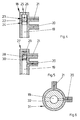
- FIG. 4 shows a changeover valve 18 as it is in the conveying devices 11, 14 used according to Figures 2 and 3 can be.
- the switching valve 18 has one with the feed pump 3 shown in FIGS. 2 and 3 connected port 19, one to the first fuel filter 7 leading connector 20 and a connector 21 for the bypass line 9, 16.
- a closing body 22 is longitudinally movable arranged, which is the terminal 21 of the bypass line 9, 16 can optionally lock or release.
- the closing body 22 has an external thread 23 and is in an internal thread 24 of the connection 19 of the feed pump 3 screwed in. Through an opening 25 is a slot 26 of the closing body 22 for attaching a not shown Turning tool accessible.
- Figure 5 shows a changeover valve 27, as it is in the conveyor 14 from Figure 3 can be used.
- the connection can be made 21 of the bypass line 16 from a longitudinally movable Release or close the closing body 28.
- the pressure in the connection increases 19 of the feed pump 3.
- the closing body 28 will then by the pressure of the feed pump 3 against the Force of the spring 29 moves until the terminal 21 of the bypass line 16 is released.
- FIG. 6 shows a changeover valve 31 as it is in the conveying devices 11, 14 from Figures 2 and 3 used can be.
- this switching valve 31 is the Connection 19 for the feed pump 3 arranged centrally. From this port 19 lead to the first fuel filter 7 connected connector 20 and connector 21 the bypass line 9, 16 away.
- a rotatable Closing body 32 allows connection 19 of the feed pump 3 optionally with the other two connections 20, 21 connect.
- the control of the closing body 32 can either electrical or manual.
Landscapes
- Engineering & Computer Science (AREA)
- Chemical & Material Sciences (AREA)
- Combustion & Propulsion (AREA)
- Mechanical Engineering (AREA)
- General Engineering & Computer Science (AREA)
- Cooling, Air Intake And Gas Exhaust, And Fuel Tank Arrangements In Propulsion Units (AREA)
- Structures Of Non-Positive Displacement Pumps (AREA)
- Pipeline Systems (AREA)
- Jet Pumps And Other Pumps (AREA)
- Filtration Of Liquid (AREA)
- Fuel-Injection Apparatus (AREA)
Applications Claiming Priority (2)
| Application Number | Priority Date | Filing Date | Title |
|---|---|---|---|
| DE10013905 | 2000-03-21 | ||
| DE10013905A DE10013905A1 (de) | 2000-03-21 | 2000-03-21 | Fördereinrichtung zum Fördern von Kraftstoff |
Publications (3)
| Publication Number | Publication Date |
|---|---|
| EP1136689A2 true EP1136689A2 (fr) | 2001-09-26 |
| EP1136689A3 EP1136689A3 (fr) | 2002-07-10 |
| EP1136689B1 EP1136689B1 (fr) | 2003-05-02 |
Family
ID=7635719
Family Applications (1)
| Application Number | Title | Priority Date | Filing Date |
|---|---|---|---|
| EP01104331A Expired - Lifetime EP1136689B1 (fr) | 2000-03-21 | 2001-02-23 | Dispositif d'alimentation en carburant |
Country Status (5)
| Country | Link |
|---|---|
| US (1) | US6422213B2 (fr) |
| EP (1) | EP1136689B1 (fr) |
| AU (1) | AU2327201A (fr) |
| BR (1) | BR0101097A (fr) |
| DE (2) | DE10013905A1 (fr) |
Cited By (5)
| Publication number | Priority date | Publication date | Assignee | Title |
|---|---|---|---|---|
| EP1826393A1 (fr) * | 2006-02-22 | 2007-08-29 | Mann+Hummel Gmbh | Système de filtration pour liquides |
| EP2009275A1 (fr) * | 2007-06-23 | 2008-12-31 | Careng automotive GmbH | Filtre et procédé de filtration d'un liquide |
| EP2017462A1 (fr) | 2007-06-21 | 2009-01-21 | Ford Global Technologies, LLC | Procédé et appareil pour nettoyer une ligne de fluide |
| ITMI20102449A1 (it) * | 2010-12-29 | 2012-06-30 | Alessandro Tommasi | Dispositivo di comando a distanza per intercettare filtri nafta, olio ed acqua, particolarmente per il settore navale, industriale ed automobilistico. |
| EP2716901A1 (fr) * | 2012-10-04 | 2014-04-09 | Peugeot Citroën Automobiles Sa | Système de filtration de carburant |
Families Citing this family (5)
| Publication number | Priority date | Publication date | Assignee | Title |
|---|---|---|---|---|
| US6817344B2 (en) * | 2002-12-30 | 2004-11-16 | Caterpillar Inc | Fuel supply system |
| DE102004005772B4 (de) * | 2004-02-05 | 2012-05-24 | Deutz Ag | Kraftstofffilter mit Sperrventil |
| DE102004046580A1 (de) * | 2004-09-23 | 2006-03-30 | Mahle Filtersysteme Gmbh | Kraftstofffilter eines insbesondere Verbrennungsmotors mit Reservefiltereinsatz |
| US7228848B1 (en) * | 2006-02-07 | 2007-06-12 | Delphi Technologies, Inc. | Self positioning filter assembly |
| SE539340C2 (en) * | 2015-07-02 | 2017-07-11 | Scania Cv Ab | Fuel system for an internal combustion engine |
Family Cites Families (16)
| Publication number | Priority date | Publication date | Assignee | Title |
|---|---|---|---|---|
| GB892692A (en) * | 1959-11-27 | 1962-03-28 | Gen Motors Corp | Gas turbine engine with fuel filter systems |
| JPS4810746B1 (fr) * | 1970-05-19 | 1973-04-06 | ||
| US4423751A (en) * | 1980-12-09 | 1984-01-03 | Cummins Engine Company, Inc. | Bypass valve and alarm assembly |
| US4366837A (en) * | 1980-12-09 | 1983-01-04 | Cummins Engine Company, Inc. | Early warning bypass valve assembly |
| DE3237964C2 (de) * | 1982-10-13 | 1986-02-20 | Dr.Ing.H.C. F. Porsche Ag, 7000 Stuttgart | Kraftstoffördersystem zur Kraftstoffversorgung eines Mehrzylinder-Flugmotors |
| US5547572A (en) * | 1985-05-14 | 1996-08-20 | Parker Hannifin Corporation | Fuel Filter |
| DE3739614A1 (de) * | 1987-11-23 | 1989-06-01 | Hengst Walter Gmbh & Co Kg | Kraftstoff-doppelfilter |
| DE4042238C2 (de) * | 1990-12-29 | 1995-08-24 | Filtertek Sa | Filter für Flüssigkeiten, insbesondere für Kraftstoffe von Verbrennungsmaschinen |
| JP3556983B2 (ja) * | 1994-12-28 | 2004-08-25 | トヨタ自動車株式会社 | 内燃機関の燃料供給装置 |
| JPH08338335A (ja) * | 1995-06-09 | 1996-12-24 | Nippondenso Co Ltd | 内燃機関の燃料供給装置 |
| DE19716979A1 (de) * | 1997-04-23 | 1998-10-29 | Porsche Ag | Kraftstoffördersystem für Fahrzeuge mit Filterüberwachung |
| US5881699A (en) * | 1997-12-22 | 1999-03-16 | Ford Global Technologies, Inc. | Diesel fuel recirculating manifold |
| AU2330399A (en) * | 1998-01-22 | 1999-08-09 | Donaldson Company Inc. | Spin-on filter assembly with valve arrangements |
| GB9802747D0 (en) * | 1998-02-09 | 1998-04-08 | Chainings Ltd | Fuel filter |
| DE19823143A1 (de) * | 1998-05-23 | 1999-11-25 | Alfmeier Praezision Ag | Kraftstoffversorgungssystem |
| DE19828931A1 (de) * | 1998-06-29 | 1999-12-30 | Bosch Gmbh Robert | Kraftstoffversorgungsvorrichtung für eine Brennkraftmaschine |
-
2000
- 2000-03-21 DE DE10013905A patent/DE10013905A1/de not_active Withdrawn
-
2001
- 2001-02-23 EP EP01104331A patent/EP1136689B1/fr not_active Expired - Lifetime
- 2001-02-23 DE DE50100201T patent/DE50100201D1/de not_active Expired - Fee Related
- 2001-02-27 AU AU23272/01A patent/AU2327201A/en not_active Abandoned
- 2001-03-13 US US09/805,788 patent/US6422213B2/en not_active Expired - Fee Related
- 2001-03-20 BR BR0101097-2A patent/BR0101097A/pt not_active Application Discontinuation
Cited By (6)
| Publication number | Priority date | Publication date | Assignee | Title |
|---|---|---|---|---|
| EP1826393A1 (fr) * | 2006-02-22 | 2007-08-29 | Mann+Hummel Gmbh | Système de filtration pour liquides |
| EP2017462A1 (fr) | 2007-06-21 | 2009-01-21 | Ford Global Technologies, LLC | Procédé et appareil pour nettoyer une ligne de fluide |
| EP2009275A1 (fr) * | 2007-06-23 | 2008-12-31 | Careng automotive GmbH | Filtre et procédé de filtration d'un liquide |
| ITMI20102449A1 (it) * | 2010-12-29 | 2012-06-30 | Alessandro Tommasi | Dispositivo di comando a distanza per intercettare filtri nafta, olio ed acqua, particolarmente per il settore navale, industriale ed automobilistico. |
| EP2716901A1 (fr) * | 2012-10-04 | 2014-04-09 | Peugeot Citroën Automobiles Sa | Système de filtration de carburant |
| FR2996603A1 (fr) * | 2012-10-04 | 2014-04-11 | Peugeot Citroen Automobiles Sa | Systeme de filtration de carburant |
Also Published As
| Publication number | Publication date |
|---|---|
| US20010027781A1 (en) | 2001-10-11 |
| BR0101097A (pt) | 2001-11-06 |
| AU2327201A (en) | 2001-09-27 |
| EP1136689B1 (fr) | 2003-05-02 |
| DE10013905A1 (de) | 2001-09-27 |
| EP1136689A3 (fr) | 2002-07-10 |
| DE50100201D1 (de) | 2003-06-05 |
| US6422213B2 (en) | 2002-07-23 |
Similar Documents
| Publication | Publication Date | Title |
|---|---|---|
| DE69715576T2 (de) | Lufteinlasssystem mit verbesserter Luftfilterzugänglichkeit | |
| DE69512285T2 (de) | Aufprallsicheres Magnetventil für ein erdgasgetriebenes Fahrzeug | |
| DE60203217T2 (de) | Staudruck Abgasrückführleitung | |
| DE19932713A1 (de) | Kraftstoffbehälter | |
| EP1136689B1 (fr) | Dispositif d'alimentation en carburant | |
| DE2851672A1 (de) | Absperrvorrichtung fuer die zuleitung eines stroemenden mediums | |
| EP1056945B1 (fr) | Soupape d'admission d'une dose de carburant volatilise | |
| DE102020123912A1 (de) | Ventilvorrichtung zur Steuerung des Durchflusses von Fluiden in zwei Temperierkreisläufen, Ausgleichsbehältervorrichtung mit einer solchen Ventilvorrichtung und Temperierkreislaufvorrichtung mit einer solchen Ausgleichsbehältervorrichtung | |
| DE10241698A1 (de) | Emissionsreinigungsvorrichtung | |
| EP0305821B1 (fr) | Dispositif pour fermer l'embranchement d'un tube | |
| DE102007043522A1 (de) | Abschalt-Vorrichtung für eine Saugstrahlpumpe, insbesondere in einem Kraftstofftank eines Kraftfahrzeugs | |
| DE102006008524B4 (de) | Mehrwege-Ventilanordnung | |
| DE19960203A1 (de) | Flüssigkeitsfilter, insbesondere Ölfilter für eine Brennkraftmaschine | |
| DE3739614A1 (de) | Kraftstoff-doppelfilter | |
| DE102016115360B4 (de) | Überströmventil zum zumindest teilweisen Verschließen und Öffnen eines Fluidleitungssystems | |
| DE3811438C2 (fr) | ||
| DE19538605A1 (de) | Luftansaugsystem | |
| DE4310452C2 (de) | Kraftstofftank für Fahrzeuge mit einer nach außerhalb des Tanks führenden Leitung | |
| DE1947441C3 (de) | Schieber-Auspuffbremse für Brennkraftmaschinen | |
| EP1118764B1 (fr) | Dispositif d'alimentation en carburant pour moteur de véhicule | |
| DE102004063065B4 (de) | Ventilanordnung zur Führung einer Flüssigkeit gegen ein Gasdruckgefälle | |
| DE102007058759A1 (de) | Rückschlagventil für eine Schmierstoffpumpe sowie Schmierstoffpumpe | |
| DE112008001318T5 (de) | Filteranordnung mit Ventil und Filter mit Vorsprung zum Eingreifen in das Ventil | |
| DE202021103120U1 (de) | Entlüftungsventil für einen Kraftstoffbehälter | |
| DE102020116049A1 (de) | Entlüftungsvorrichtung |
Legal Events
| Date | Code | Title | Description |
|---|---|---|---|
| PUAI | Public reference made under article 153(3) epc to a published international application that has entered the european phase |
Free format text: ORIGINAL CODE: 0009012 |
|
| AK | Designated contracting states |
Kind code of ref document: A2 Designated state(s): AT BE CH CY DE DK ES FI FR GB GR IE IT LI LU MC NL PT SE TR |
|
| AX | Request for extension of the european patent |
Free format text: AL;LT;LV;MK;RO;SI |
|
| RAP1 | Party data changed (applicant data changed or rights of an application transferred) |
Owner name: SIEMENS AKTIENGESELLSCHAFT |
|
| PUAL | Search report despatched |
Free format text: ORIGINAL CODE: 0009013 |
|
| AK | Designated contracting states |
Kind code of ref document: A3 Designated state(s): AT BE CH CY DE DK ES FI FR GB GR IE IT LI LU MC NL PT SE TR |
|
| AX | Request for extension of the european patent |
Free format text: AL;LT;LV;MK;RO;SI |
|
| 17P | Request for examination filed |
Effective date: 20020708 |
|
| GRAH | Despatch of communication of intention to grant a patent |
Free format text: ORIGINAL CODE: EPIDOS IGRA |
|
| GRAH | Despatch of communication of intention to grant a patent |
Free format text: ORIGINAL CODE: EPIDOS IGRA |
|
| GRAA | (expected) grant |
Free format text: ORIGINAL CODE: 0009210 |
|
| AKX | Designation fees paid |
Designated state(s): DE ES FR GB SE |
|
| AK | Designated contracting states |
Designated state(s): DE ES FR GB SE |
|
| PG25 | Lapsed in a contracting state [announced via postgrant information from national office to epo] |
Ref country code: FR Free format text: LAPSE BECAUSE OF FAILURE TO SUBMIT A TRANSLATION OF THE DESCRIPTION OR TO PAY THE FEE WITHIN THE PRESCRIBED TIME-LIMIT Effective date: 20030502 Ref country code: GB Free format text: LAPSE BECAUSE OF FAILURE TO SUBMIT A TRANSLATION OF THE DESCRIPTION OR TO PAY THE FEE WITHIN THE PRESCRIBED TIME-LIMIT Effective date: 20030502 |
|
| REG | Reference to a national code |
Ref country code: GB Ref legal event code: FG4D Free format text: NOT ENGLISH |
|
| REF | Corresponds to: |
Ref document number: 50100201 Country of ref document: DE Date of ref document: 20030605 Kind code of ref document: P |
|
| REG | Reference to a national code |
Ref country code: IE Ref legal event code: FG4D Free format text: GERMAN |
|
| PG25 | Lapsed in a contracting state [announced via postgrant information from national office to epo] |
Ref country code: SE Free format text: LAPSE BECAUSE OF FAILURE TO SUBMIT A TRANSLATION OF THE DESCRIPTION OR TO PAY THE FEE WITHIN THE PRESCRIBED TIME-LIMIT Effective date: 20030802 |
|
| PG25 | Lapsed in a contracting state [announced via postgrant information from national office to epo] |
Ref country code: ES Free format text: LAPSE BECAUSE OF FAILURE TO SUBMIT A TRANSLATION OF THE DESCRIPTION OR TO PAY THE FEE WITHIN THE PRESCRIBED TIME-LIMIT Effective date: 20030813 |
|
| GBV | Gb: ep patent (uk) treated as always having been void in accordance with gb section 77(7)/1977 [no translation filed] |
Effective date: 20030502 |
|
| REG | Reference to a national code |
Ref country code: IE Ref legal event code: FD4D Ref document number: 1136689E Country of ref document: IE |
|
| PLBE | No opposition filed within time limit |
Free format text: ORIGINAL CODE: 0009261 |
|
| STAA | Information on the status of an ep patent application or granted ep patent |
Free format text: STATUS: NO OPPOSITION FILED WITHIN TIME LIMIT |
|
| 26N | No opposition filed |
Effective date: 20040203 |
|
| EN | Fr: translation not filed | ||
| PG25 | Lapsed in a contracting state [announced via postgrant information from national office to epo] |
Ref country code: DE Free format text: LAPSE BECAUSE OF NON-PAYMENT OF DUE FEES Effective date: 20040901 |