EP2017485A2 - Connecting device - Google Patents
Connecting device Download PDFInfo
- Publication number
- EP2017485A2 EP2017485A2 EP08104126A EP08104126A EP2017485A2 EP 2017485 A2 EP2017485 A2 EP 2017485A2 EP 08104126 A EP08104126 A EP 08104126A EP 08104126 A EP08104126 A EP 08104126A EP 2017485 A2 EP2017485 A2 EP 2017485A2
- Authority
- EP
- European Patent Office
- Prior art keywords
- threaded rod
- threaded
- fixing
- adjusting
- sleeve member
- Prior art date
- Legal status (The legal status is an assumption and is not a legal conclusion. Google has not performed a legal analysis and makes no representation as to the accuracy of the status listed.)
- Granted
Links
- 230000000903 blocking effect Effects 0.000 claims description 13
- 238000006073 displacement reaction Methods 0.000 description 3
- 238000009434 installation Methods 0.000 description 2
- 238000004873 anchoring Methods 0.000 description 1
- 230000015572 biosynthetic process Effects 0.000 description 1
- 239000002981 blocking agent Substances 0.000 description 1
- 230000006835 compression Effects 0.000 description 1
- 238000007906 compression Methods 0.000 description 1
- 238000011161 development Methods 0.000 description 1
- 230000018109 developmental process Effects 0.000 description 1
- 238000000034 method Methods 0.000 description 1
- 239000000758 substrate Substances 0.000 description 1
- 238000009423 ventilation Methods 0.000 description 1
Images
Classifications
-
- F—MECHANICAL ENGINEERING; LIGHTING; HEATING; WEAPONS; BLASTING
- F16—ENGINEERING ELEMENTS AND UNITS; GENERAL MEASURES FOR PRODUCING AND MAINTAINING EFFECTIVE FUNCTIONING OF MACHINES OR INSTALLATIONS; THERMAL INSULATION IN GENERAL
- F16B—DEVICES FOR FASTENING OR SECURING CONSTRUCTIONAL ELEMENTS OR MACHINE PARTS TOGETHER, e.g. NAILS, BOLTS, CIRCLIPS, CLAMPS, CLIPS OR WEDGES; JOINTS OR JOINTING
- F16B37/00—Nuts or like thread-engaging members
- F16B37/08—Quickly-detachable or mountable nuts, e.g. consisting of two or more parts; Nuts movable along the bolt after tilting the nut
- F16B37/0807—Nuts engaged from the end of the bolt, e.g. axially slidable nuts
- F16B37/0864—Nuts engaged from the end of the bolt, e.g. axially slidable nuts with the threaded portions of the nut engaging the thread of the bolt by pressing or rotating an external retaining member such as a cap, a nut, a ring or a sleeve
-
- F—MECHANICAL ENGINEERING; LIGHTING; HEATING; WEAPONS; BLASTING
- F16—ENGINEERING ELEMENTS AND UNITS; GENERAL MEASURES FOR PRODUCING AND MAINTAINING EFFECTIVE FUNCTIONING OF MACHINES OR INSTALLATIONS; THERMAL INSULATION IN GENERAL
- F16B—DEVICES FOR FASTENING OR SECURING CONSTRUCTIONAL ELEMENTS OR MACHINE PARTS TOGETHER, e.g. NAILS, BOLTS, CIRCLIPS, CLAMPS, CLIPS OR WEDGES; JOINTS OR JOINTING
- F16B37/00—Nuts or like thread-engaging members
- F16B37/08—Quickly-detachable or mountable nuts, e.g. consisting of two or more parts; Nuts movable along the bolt after tilting the nut
- F16B37/0807—Nuts engaged from the end of the bolt, e.g. axially slidable nuts
- F16B37/0857—Nuts engaged from the end of the bolt, e.g. axially slidable nuts with the threaded portions of the nut engaging the thread of the bolt by the action of one or more springs or resilient retaining members
Definitions
- the invention relates to a tying device for a threaded rod with a fastening element for fixing the tether to a component and with an adjusting device for the threaded rod, wherein the adjusting device rotatably mounted in the fastener sleeve member having an internal thread for the threaded rod and at a first end portion a radially from Having the sleeve member projecting projection for engaging behind the fastener.
- the pipes are arranged in pipe clamps and fixed by threaded rods on a component or a substrate.
- a tying device for a threaded rod on a component in the form of a mounting rail which has a fastening element and an adjusting device for the threaded rod.
- the adjusting device has a rotatably mounted in the fastening element sleeve element with an internal thread for the threaded rod and with an external thread.
- a radially projecting from this projection for engaging behind the fastener is provided.
- a clamping nut is screwed onto the external thread of the sleeve member until the tethering device is fixed to the component.
- the threaded rod to be fixed to the tying device is screwed into the internal thread and fixed according to the desired orientation with respect to the mounting rail with a locking nut arranged on the threaded rod in this position.
- a disadvantage of the known solution is that the threaded rod must be screwed, which is costly in a larger anchoring length of the threaded rod in the tether.
- the object of the invention is to provide a tying device for adjustable threaded rods, which allows not only a fine adjustment but also a simple coarse adjustment or a quick connection of the threaded rod.
- the internal thread of the sleeve member is formed by at least two threaded jaws, which are mounted displaceably in recesses of the sleeve member in the radial direction. Further, a rotatably connected to the sleeve member and axially displaceable to this fixing is provided which fixes the threaded jaws in a position engaging in the thread of the threaded rod in a fixing position.
- the threaded jaws are displaceable in the radial direction relative to the longitudinal axis of the attachment device or of the sleeve element.
- the tying device can simply be pushed onto the free end of the threaded rod, with the threaded jaws mounted in the sleeve element deflecting radially outward.
- the threaded rod By turning the sleeve member, the threaded rod, which engages over the threaded jaws with the sleeve member, adjusted in height or at a distance to the component, without a rotation of the threaded rod and an element arranged thereon, such as a pipe clamp takes place.
- a significant advantage of the tying device according to the invention lies in the flexibility of the application, which at all times a fine as well as a Coarse adjustment of the threaded rod arranged thereon and also a quick connection of the threaded rod to the tethering allowed.
- openings for the implementation of fasteners such. B. screws provided in the fastener, which allow an arrangement of the tether on the component.
- the entire adjusting device is rotatably mounted in the fastening element via the sleeve element and ensures the fixation of the threaded rod in the axial direction.
- mounting rails are advantageously provided as components on which the threaded rods are fixed.
- Such mounting rails have at least one in the longitudinal extent of the mounting rail extending, limited by spaced edges mounting opening.
- the fastening element is designed, for example, as a rear engagement part which advantageously has a length which is smaller than the distance between the edges bounding the mounting opening of the mounting rail and a width which is greater than the distance of the edges the mounting opening is one another.
- a fastener can be inserted through the mounting hole in the mounting rail and be brought by a rotation of the tether about the longitudinal axis of about 90 ° in a position engaging behind the mounting hole. In the unstressed position of the tether this is displaceable for positioning of the clamp along the mounting rail.
- a spring element is provided for spring loading of the fastening element between the projection arranged on the first end region of the sleeve element and the fastening element.
- the spring element is a compression spring and, for example, designed as a spiral spring.
- the spring element biases the fastening element in the direction of the free, the first end region of the sleeve member opposite end of the sleeve member, so that after the arrangement of the tether on a component with a limited by edges mounting opening, such. B. a mounting rail, the tether z. B. is held self-locking in conjunction with a arranged on the threaded rod locking means. Due to the self-locking displaceability of the tether in the mounting hole is also For vertically aligned components ensures easy mounting of the tether.
- the tether comprises a stop element between the rear engagement part and z. B. is provided a securing means.
- the stop element comes into contact with the outside of the mounting rail.
- the adjustment is advantageous on the outside of the stop and is rotatable to this. If the component has a mounting opening delimited by edges, then the areas of the edges bounding the mounting opening are clamped between the fastening element and the stop element during bracing of the tether.
- the tethering device is advantageously provided preassembled to the user, wherein the individual parts of the tethering device are further advantageously connected to one another in a captive manner.
- a spring element is provided for the radial spring loading of the threaded jaws, which biases the threaded jaws radially inward relative to the sleeve element. This ensures a secure engagement of the threaded jaws in the thread of the threaded rod as soon as they are no longer pressed radially outward by the threaded rod pushed in the direction of the longitudinal axis.
- the fixing means preferably comprises blocking elements for fixing the threaded jaws. If the blocking agent from its release position in the fixing position, z. B. axially offset in the direction of the fastener, the blocking elements come with the threaded jaws in abutment and fix them in an engaging in the thread of the threaded rod position, so that the threaded jaws are secured radially immovable.
- the blocking elements are in the fixing position of the fixing means on the radially outer side outer surface of the threaded jaws.
- the blocking elements are guided in at least one axial receptacle in the sleeve member and form the rotationally fixed connection between the adjusting element and the sleeve member.
- the axial receptacle is, for example, a bore which opens from a second, the first end region opposite end of the sleeve element, starting in the recesses for the internal thread of the sleeve member forming thread jaws.
- blocking elements are provided for fixing the threaded jaws on the adjusting element, wherein the blocking elements protrude from the adjusting element in the direction of the fastening element.
- Sleeve member axially displaceable, which allows easy displacement of the adjustment.
- the blocking elements are guided in at least one axial receptacle in the sleeve member.
- the axial receptacle is, for example, a bore which opens from a second, the first end region opposite end of the sleeve element, starting in the recesses for the internal thread of the sleeve member forming thread jaws.
- an adjustment is provided, wherein the fixing project from the adjusting element in the direction of the fastening element and form a rotationally fixed connection between the adjusting element and the sleeve member.
- the fine adjustment of the fixed in the tether threaded rod is simplified by the adjustment.
- the adjusting member By turning the adjusting member rotatably connected to the sleeve member, the sleeve member is rotated and the threaded rod in the height or at a distance to the component adjusted without rotation of the threaded rod and an element arranged thereon, such as a pipe clamp takes place.
- the adjustment forms an abutment. When tightening the tether, the areas of the mounting opening bounding edges are clamped during bracing of the tether between the fastener and the setting directly or in the presence of a stop element indirectly on this.
- the adjusting element preferably has a stop facing the fastening element, which restricts the axial displaceability of the adjusting element in the direction of the fastening element.
- a rotary handle e.g. B. for a tool provided on the adjusting element, which allows a simple fine adjustment of the fixed in the tether threaded rod.
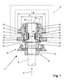
- FIGS. 1 and 2 is a tethering device 11 for a load adjustable threaded rod 5 for fixing to a component, shown here on a mounting rail 6.
- the mounting rail 6 has an extending in the longitudinal extent of the mounting rail 6 mounting opening 7, which is bounded by mutually spaced at a distance A edges 8.
- the tethering device 11 comprises a fastening element 31 for fixing the tethering device 11 to a component, wherein the fastening element 31 is designed as a rear engagement part for the areawise engagement of the edges 8 of the mounting rail 6 delimiting the mounting opening 7.
- the fastening element 31 advantageously has a length which is smaller than the distance A between the mounting opening 7 of the mounting rail 6 bounding edges 8 to each other, and a width B, which is greater than the distance A of the edges 8 of the mounting hole 7 to each other.
- the fastening element 31 is provided on two mutually opposite side edges, which come into engagement with the mounting rail 6 in the engagement state of the fastening element 31, with a profiling formed as a toothing.
- the tethering device 11 comprises an adjusting device 12 for the threaded rod 5, wherein the adjusting device 12 a rotatably mounted in the fastening element 31 sleeve member 13 with an internal thread, which is formed by two thread jaws 14, for the threaded rod 5 and at a first end portion 20 a radially Having protruding from the sleeve member 13 projection 17 for engaging behind the fastener 31 has.
- the internal thread forming threaded jaws 14 are mounted radially displaceable in the longitudinal axis 26 of the tether 11 in recesses 15 of the sleeve member 13 and spring-loaded by a threaded jaws 14 on the outside surrounding spring element 16 radially inwardly.
- the adjusting device 12 a rotatably connected to the sleeve member 13 and axially displaceable to this fixing means for fixing the threaded jaws 14 in the form of two blocking elements 23 which protrude from an adjusting member 21 in the direction of the fastening element 31.
- the blocking elements 23 are guided in an axial receptacle 19 in the sleeve member 13 and form the rotationally fixed connection between the Adjustment element 21 and the sleeve member 13 from.
- the fixing fix in a fixing position the threaded jaws 14 in an engaging in the thread of the threaded rod 5 position.
- a stop 24 facing the fastening element 31 is provided which limits the axial displaceability of the adjusting element 21 in the direction of the fastening element 31.
- a hexagonal formation is provided as a rotary handle 22 for a clamping tool.
- a spring element 36 for spring loading of the fastening element 31 in the direction of the adjusting element 21 is provided between the first end portion 20 of the sleeve member 13 circumferentially arranged projection 17 and the fastening element 31. Furthermore, the tethering device 11 between the fastening element 31 and the adjusting element 21 comprises a stop element 41 which can be brought into contact with the outside of the mounting rail 6.
- the fastening element 31 of the tethering device 11 which may be arranged on the threaded rod 5 before the assembly on the mounting rail 6, inserted at the desired location in the mounting rail 6 and the entire tethering device 11 about its longitudinal axis 26th rotated by about 90 °, so that the side edges of the fastener 31 engage behind the edges 8 of the mounting hole 7.
- the tying device 11 is self-lockingly displaceable along the mounting opening 7.
- the adjusting element 21 and thus the fixing means are in the, with reference to the drawing retracted release position (see Fig. 1 ), in which the blocking elements 23 do not limit the displaceability of the threaded jaws 14 radially outwards.
- the threaded rod 5 is inserted in the direction of arrow 4 in the arranged on the mounting rail 6 tether 11, wherein the threaded jaws 14 dodge radially outward (see double arrow 18 in Fig. 1 ). If there is no further displacement of the threaded rod 5 along the longitudinal axis 26, the threaded jaws 14 engage in the thread of the threaded rod 5 and secure the threaded rod 5 in the axial direction. Now the line to be fastened (not shown here) is inserted into the pipe clamp.
- the rotatably mounted in the fastening element 31 sleeve member 13 is rotated about the fixing means, wherein over the thread with the threaded rod 5 engaged threaded jaws 14 of the sleeve member 13, the threaded rod 5 according to the direction of rotation of the adjusting member 21 along the longitudinal axis 26th the tether 11 in the direction of the double arrow 9 is shifted toward the mounting rail 6 or away from it.
- This will be the Position of the arranged in the pipe clamp line perpendicular to the longitudinal direction of the component forming mounting rail 6 set.
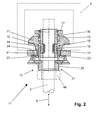
- the adjusting element 21 and thus the fixing means is displaced axially in the direction of the fastening element 31 and thereby brought into the fixing position.
- the blocking elements 23 of the adjusting element 21 engage behind the threaded jaws 14 in the fixing position and secure them against dodging radially outwards.
- the fastener 31 facing the stop 24 on the adjusting element 21 limits the axial displacement of the adjusting element 21 in the direction of the fastening element 31.
- the threaded rod 5 is inserted before the arrangement of the tethering device 11 on the component in the tethering device 11 and this set simultaneously with the tethering device 11 on the component.
- the fixing means can be displaced axially in the direction of the fastening element 31 even before the fine adjustment of the threaded rod 5, since the fine adjustment can also take place in this position of the fixing means.
- a subsequent fine and coarse adjustment of the line is possible at any time with the tethering device 11 according to the invention with a loosened locknut 46.
Landscapes
- Engineering & Computer Science (AREA)
- General Engineering & Computer Science (AREA)
- Mechanical Engineering (AREA)
- Mutual Connection Of Rods And Tubes (AREA)
- Clamps And Clips (AREA)
Abstract
Description
Die Erfindung betrifft eine Anbindevorrichtung für eine Gewindestange mit einem Befestigungselement zur Festlegung der Anbindevorrichtung an einem Bauteil und mit einer Justiereinrichtung für die Gewindestange, wobei die Justiereinrichtung ein drehbar in dem Befestigungselement gelagertes Hülsenelement mit einem Innengewinde für die Gewindestange sowie an einem ersten Endbereich einen radial von dem Hülsenelement abragenden Vorsprung zum Hintergreifen des Befestigungselementes aufweist.The invention relates to a tying device for a threaded rod with a fastening element for fixing the tether to a component and with an adjusting device for the threaded rod, wherein the adjusting device rotatably mounted in the fastener sleeve member having an internal thread for the threaded rod and at a first end portion a radially from Having the sleeve member projecting projection for engaging behind the fastener.
Für eine flexible Installation von Leitungen, wie Rohren, Lüftungskanälen, Elektrokabeltrassen und dergleichen, im Bereich der Haustechnik oder der Industrie werden die Leitungen in Rohrschellen angeordnet und über Gewindestangen an einem Bauteil oder einem Untergrund festgelegt.For a flexible installation of pipes, such as pipes, ventilation ducts, electrical cable trays and the like, in the field of building services or industry, the pipes are arranged in pipe clamps and fixed by threaded rods on a component or a substrate.
Aus der
Nach dem Einlegen der Leitungen in die Rohrschellen ist es oftmals erforderlich, z. B. aufgrund von Unebenheiten des Untergrundes oder zur Gewährleistung eines Gefälles der zu fixierenden Leitung, die Anbindung nachträglich in der Höhe zu justieren und somit die Leitungen jeweils im gewünschten Abstand zum Untergrund auszurichten.After inserting the lines in the clamps, it is often necessary, for. B. due to unevenness of the ground or to ensure a gradient of to be fixed line to adjust the connection later in height and thus align the lines each at the desired distance to the ground.
Nachteilig an der bekannten Lösung ist, dass die Gewindestange eingeschraubt werden muss, was bei einer grösseren Verankerungslänge der Gewindestange in der Anbindevorrichtung aufwändig ist.A disadvantage of the known solution is that the threaded rod must be screwed, which is costly in a larger anchoring length of the threaded rod in the tether.
Aufgabe der Erfindung ist es, eine Anbindevorrichtung für justierbare Gewindestangen zu schaffen, die neben einer Feinjustierung auch eine einfache Grobjustierung beziehungsweise eine Schnellanbindung der Gewindestange ermöglicht.The object of the invention is to provide a tying device for adjustable threaded rods, which allows not only a fine adjustment but also a simple coarse adjustment or a quick connection of the threaded rod.
Die Aufgabe ist durch die Merkmale des unabhängigen Anspruchs gelöst. Vorteilhafte Weiterbildungen sind in den Unteransprüchen dargelegt.The object is solved by the features of the independent claim. Advantageous developments are set forth in the subclaims.
Gemäss der Erfindung ist das Innengewinde des Hülsenelementes von zumindest zwei Gewindebacken gebildet, die in Ausnehmungen des Hülsenelementes in radialer Richtung verschieblich gelagert sind. Ferner ist ein drehfest mit dem Hülsenelement verbundenes und axial zu diesem versetzbares Fixiermittel vorgesehen, das in einer Fixierstellung die Gewindebacken in einer in das Gewinde der Gewindestange eingreifenden Stellung fixiert.According to the invention, the internal thread of the sleeve member is formed by at least two threaded jaws, which are mounted displaceably in recesses of the sleeve member in the radial direction. Further, a rotatably connected to the sleeve member and axially displaceable to this fixing is provided which fixes the threaded jaws in a position engaging in the thread of the threaded rod in a fixing position.
In einer Freigabestellung des Fixiermittels sind die Gewindebacken in radialer Richtung bezogen auf die Längsachse der Anbindevorrichtung beziehungsweise des Hülsenelementes verschieblich. Die Anbindevorrichtung kann in der Freigabestellung des Fixiermittels einfach auf das freie Ende der Gewindestange geschoben werden, wobei die im Hülsenelement gelagerten Gewindebacken radial nach aussen ausweichen. Sobald der Vorschub der Gewindestange in Richtung der Längsachse der Anbindevorrichtung unterbrochen wird, greifen die zumindest zwei Gewindebacken wieder in das Gewinde der Gewindestange ein. Das entsprechende Ende der Gewindestange kann auch in eine bereits am Bauteil festgelegte Anbindevorrichtung eingeschoben werden.In a release position of the fixing means, the threaded jaws are displaceable in the radial direction relative to the longitudinal axis of the attachment device or of the sleeve element. In the release position of the fixing means, the tying device can simply be pushed onto the free end of the threaded rod, with the threaded jaws mounted in the sleeve element deflecting radially outward. Once the feed of the threaded rod is interrupted in the direction of the longitudinal axis of the tether, engage the at least two threaded jaws back into the thread of the threaded rod. The corresponding end of the threaded rod can also be inserted into an already fixed to the component tether.
Durch Drehen des Hülsenelementes wird die Gewindestange, welche über die Gewindebacken mit dem Hülsenelement in Eingriff steht, in der Höhe beziehungsweise im Abstand zu dem Bauteil justiert, ohne dass eine Rotation der Gewindestange und einem daran angeordneten Element, wie beispielsweise einer Rohrschelle erfolgt. Dadurch kann die Gewindestange einfach auch unter Last in der Höhe feinjustiert werden. Anschliessend wird beispielsweise ein auf der Gewindestange angeordnetes Sicherungsmittel, z. B. in Form einer Sicherungsmutter zur Sicherung der Anbindung mit der Justiereinrichtung in Anlage gebracht. Ein wesentlicher Vorteil der erfindungsgemässen Anbindevorrichtung liegt in der Flexibilität der Anwendung, welche zu jedem Zeitpunkt eine Fein- wie auch eine Grobjustierung der daran angeordneten Gewindestange und zudem eine Schnellanbindung der Gewindestange an der Anbindevorrichtung erlaubt.By turning the sleeve member, the threaded rod, which engages over the threaded jaws with the sleeve member, adjusted in height or at a distance to the component, without a rotation of the threaded rod and an element arranged thereon, such as a pipe clamp takes place. This allows the threaded rod to be easily adjusted even under load in height. Subsequently, for example, arranged on the threaded rod securing means, for. B. brought in the form of a lock nut to secure the connection with the adjustment system. A significant advantage of the tying device according to the invention lies in the flexibility of the application, which at all times a fine as well as a Coarse adjustment of the threaded rod arranged thereon and also a quick connection of the threaded rod to the tethering allowed.
In einer Ausführungsform der Erfindung sind beispielsweise Öffnungen für die Durchführung von Befestigungsmitteln, wie z. B. Schrauben in dem Befestigungselement vorgesehen, welche eine Anordnung der Anbindevorrichtung am Bauteil ermöglichen. Die gesamte Justiereinrichtung ist über das Hülsenelement drehbar in dem Befestigungselement gelagert und stellt die Fixierung der Gewindestange in axialer Richtung sicher.In one embodiment of the invention, for example, openings for the implementation of fasteners, such. B. screws provided in the fastener, which allow an arrangement of the tether on the component. The entire adjusting device is rotatably mounted in the fastening element via the sleeve element and ensures the fixation of the threaded rod in the axial direction.
Für eine einfache und flexible Installation von Leitungen werden vorteilhafterweise Montageschienen als Bauteile vorgesehen, an denen die Gewindestangen festgelegt werden. Derartige Montageschienen weisen zumindest eine in Längserstreckung der Montageschiene verlaufende, von zueinander beabstandeten Rändern begrenzte Montageöffnung auf.For a simple and flexible installation of cables mounting rails are advantageously provided as components on which the threaded rods are fixed. Such mounting rails have at least one in the longitudinal extent of the mounting rail extending, limited by spaced edges mounting opening.
Zur Ausbildung einer an einer solchen Montageschiene anordnenbaren Anbindevorrichtung ist das Befestigungselement beispielsweise als ein Hintergreifteil ausgebildet, das vorteilhaft eine Länge, die kleiner als der Abstand der die Montageöffnung der Montageschiene begrenzenden Ränder zueinander ist, sowie eine Breite aufweist, die grösser als der Abstand der Ränder der Montageöffnung zueinander ist. Ein derartiges Befestigungselement kann durch die Montageöffnung in die Montageschiene eingeführt und durch eine Drehung der Anbindevorrichtung um die Längsachse von etwa 90° in eine die Montageöffnung hintergreifende Stellung gebracht werden. In der unverspannten Stellung der Anbindevorrichtung ist diese für eine Positionierung der Rohrschelle entlang der Montageschiene verschiebbar. Beim Verspannen der Anbindevorrichtung werden Bereiche der die Montageöffnung begrenzenden Ränder zwischen dem Befestigungselement und einem Sicherungsmittel eingeklemmt.To form a tying device which can be arranged on such a mounting rail, the fastening element is designed, for example, as a rear engagement part which advantageously has a length which is smaller than the distance between the edges bounding the mounting opening of the mounting rail and a width which is greater than the distance of the edges the mounting opening is one another. Such a fastener can be inserted through the mounting hole in the mounting rail and be brought by a rotation of the tether about the longitudinal axis of about 90 ° in a position engaging behind the mounting hole. In the unstressed position of the tether this is displaceable for positioning of the clamp along the mounting rail. When bracing the tether portions of the mounting opening bounding edges between the fastener and a securing means are clamped.
Weiter vorteilhaft ist ein Federelement zur Federbeaufschlagung des Befestigungselementes zwischen dem am ersten Endbereich des Hülsenelementes angeordneten Vorsprung und dem Befestigungselement vorgesehen. Das Federelement ist eine Druckfeder und beispielsweise als Spiralfeder ausgebildet. Das Federelement spannt das Befestigungselement in Richtung des freien, dem ersten Endbereich des Hülsenelementes gegenüberliegenden Endes des Hülsenelementes vor, so dass nach der Anordnung der Anbindevorrichtung an einem Bauteil mit einer von Rändern begrenzten Montageöffnung, wie z. B. eine Montageschiene, die Anbindevorrichtung z. B. in Verbindung mit einem auf der Gewindestange angeordneten Sicherungsmittel selbsthemmend gehalten ist. Infolge der selbsthemmenden Verschiebbarkeit der Anbindevorrichtung in der Montageöffnung ist auch bei vertikal ausgerichteten Bauteilen eine einfache Montage der Anbindevorrichtung gewährleistet.Further advantageously, a spring element is provided for spring loading of the fastening element between the projection arranged on the first end region of the sleeve element and the fastening element. The spring element is a compression spring and, for example, designed as a spiral spring. The spring element biases the fastening element in the direction of the free, the first end region of the sleeve member opposite end of the sleeve member, so that after the arrangement of the tether on a component with a limited by edges mounting opening, such. B. a mounting rail, the tether z. B. is held self-locking in conjunction with a arranged on the threaded rod locking means. Due to the self-locking displaceability of the tether in the mounting hole is also For vertically aligned components ensures easy mounting of the tether.
Weiter vorteilhaft umfasst die Anbindevorrichtung ein Anschlagelement, das zwischen dem Hintergreifteil und z. B. einem Sicherungsmittel vorgesehen ist. Das Anschlagelement kommt mit der Aussenseite der Montageschiene in Anlage. Das Einstellelement liegt vorteilhaft an der Aussenseite des Anschlags an und ist zu diesem verdrehbar. Weist das Bauteil eine von Rändern begrenzte Montageöffnung auf, so werden die Bereiche der die Montageöffnung begrenzenden Ränder beim Verspannen der Anbindevorrichtung zwischen dem Befestigungselement und dem Anschlagelement eingeklemmt.Further advantageously, the tether comprises a stop element between the rear engagement part and z. B. is provided a securing means. The stop element comes into contact with the outside of the mounting rail. The adjustment is advantageous on the outside of the stop and is rotatable to this. If the component has a mounting opening delimited by edges, then the areas of the edges bounding the mounting opening are clamped between the fastening element and the stop element during bracing of the tether.
Die Anbindevorrichtung wird dem Anwender vorteilhaft vormontiert zur Verfügung gestellt, wobei die einzelnen Teile der Anbindevorrichtung weiter vorteilhaft unverlierbar miteinander verbunden sind.The tethering device is advantageously provided preassembled to the user, wherein the individual parts of the tethering device are further advantageously connected to one another in a captive manner.
Vorzugsweise ist ein Federelement zur radialen Federbeaufschlagung der Gewindebacken vorgesehen, welches die Gewindebacken bezogen auf das Hülsenelement nach radial innen vorspannt. Dies gewährleistet einen sicheren Eingriff der Gewindebacken in das Gewinde der Gewindestange sobald diese nicht mehr von der in Richtung der Längsachse geschobenen Gewindestange nach radial aussen gedrückt werden.Preferably, a spring element is provided for the radial spring loading of the threaded jaws, which biases the threaded jaws radially inward relative to the sleeve element. This ensures a secure engagement of the threaded jaws in the thread of the threaded rod as soon as they are no longer pressed radially outward by the threaded rod pushed in the direction of the longitudinal axis.
Bevorzugt umfasst das Fixiermittel Blockierelemente zur Fixierung der Gewindebacken. Werden die Blockiermittel von ihrer Freigabestellung in die Fixierstellung, z. B. in Richtung des Befestigungselementes axial versetzt, kommen die Blockierelemente mit den Gewindebacken in Anlage und fixieren diese in einer in das Gewinde der Gewindestange eingreifenden Position, so dass die Gewindebacken radial unverschieblich gesichert sind. Vorteilhaft liegen die Blockierelemente in der Fixierstellung des Fixiermittels an der radial aussenseitigen Aussenfläche der Gewindebacken an.The fixing means preferably comprises blocking elements for fixing the threaded jaws. If the blocking agent from its release position in the fixing position, z. B. axially offset in the direction of the fastener, the blocking elements come with the threaded jaws in abutment and fix them in an engaging in the thread of the threaded rod position, so that the threaded jaws are secured radially immovable. Advantageously, the blocking elements are in the fixing position of the fixing means on the radially outer side outer surface of the threaded jaws.
Vorzugsweise sind die Blockierelemente in zumindest einer axialen Aufnahme im Hülsenelement geführt und bilden die drehfeste Verbindung zwischen dem Einstellelement und dem Hülsenelement aus. Die axiale Aufnahme ist beispielsweise eine Bohrung die von einem zweiten, dem ersten Endbereich gegenüberliegenden Ende des Hülsenelementes ausgehend in die Ausnehmungen für die das Innengewinde des Hülsenelementes bildenden Gewindebacken mündet.Preferably, the blocking elements are guided in at least one axial receptacle in the sleeve member and form the rotationally fixed connection between the adjusting element and the sleeve member. The axial receptacle is, for example, a bore which opens from a second, the first end region opposite end of the sleeve element, starting in the recesses for the internal thread of the sleeve member forming thread jaws.
Bevorzugt sind Blockierelemente zur Fixierung der Gewindebacken an dem Einstellelement vorgesehen, wobei die Blockierelemente von dem Einstellelement in Richtung des Befestigungselementes abragen. Weiter vorteilhaft ist das Einstellelement zum Hülsenelement axial verschiebbar, was ein einfaches Versetzen des Einstellelementes ermöglicht.Preferably, blocking elements are provided for fixing the threaded jaws on the adjusting element, wherein the blocking elements protrude from the adjusting element in the direction of the fastening element. Next advantageous is the adjustment for Sleeve member axially displaceable, which allows easy displacement of the adjustment.
Bevorzugt sind die Blockierelemente in zumindest einer axialen Aufnahme im Hülsenelement geführt. Die axiale Aufnahme ist beispielsweise eine Bohrung die von einem zweiten, dem ersten Endbereich gegenüberliegenden Ende des Hülsenelementes ausgehend in die Ausnehmungen für die das Innengewinde des Hülsenelementes bildenden Gewindebacken mündet.Preferably, the blocking elements are guided in at least one axial receptacle in the sleeve member. The axial receptacle is, for example, a bore which opens from a second, the first end region opposite end of the sleeve element, starting in the recesses for the internal thread of the sleeve member forming thread jaws.
Vorzugsweise ist ein Einstellelement vorgesehen, wobei die Fixiermittel von dem Einstellelement in Richtung des Befestigungselementes abragen und eine drehfeste Verbindung zwischen dem Einstellelement und dem Hülsenelement ausbilden. Die Feinjustierung der in der Anbindevorrichtung festgelegten Gewindestange ist durch das Einstellelement vereinfacht. Durch Drehen des drehfest mit dem Hülsenelement verbundenen Einstellelementes wird das Hülsenelement gedreht und die Gewindestange in der Höhe beziehungsweise im Abstand zu dem Bauteil justiert, ohne dass eine Rotation der Gewindestange und einem daran angeordneten Element, wie beispielsweise einer Rohrschelle erfolgt. Bei einer Anbindevorrichtung, die als Befestigungselement ein Hintergreifteil zur Anordnung der Anbindevorrichtung beispielsweise an einer Montageschiene aufweist, bildet das Einstellelement ein Gegenlager aus. Beim Verspannen der Anbindevorrichtung werden die Bereiche der die Montageöffnung begrenzenden Ränder beim Verspannen der Anbindevorrichtung zwischen dem Befestigungselement und dem Einstellelement direkt oder bei Vorhandensein eines Anschlagelementes indirekt über dieses eingeklemmt.Preferably, an adjustment is provided, wherein the fixing project from the adjusting element in the direction of the fastening element and form a rotationally fixed connection between the adjusting element and the sleeve member. The fine adjustment of the fixed in the tether threaded rod is simplified by the adjustment. By turning the adjusting member rotatably connected to the sleeve member, the sleeve member is rotated and the threaded rod in the height or at a distance to the component adjusted without rotation of the threaded rod and an element arranged thereon, such as a pipe clamp takes place. In a tether, which has a rear engagement part for the arrangement of the tether, for example on a mounting rail as a fastener, the adjustment forms an abutment. When tightening the tether, the areas of the mounting opening bounding edges are clamped during bracing of the tether between the fastener and the setting directly or in the presence of a stop element indirectly on this.
Bevorzugt weist das Einstellelement einen dem Befestigungselement zugewandeten Anschlag auf, der die axiale Verschiebbarkeit des Einstellelementes in Richtung des Befestigungselementes beschränkt. Vorteilhaft ist der Abstand des Einstellelementes zum Befestigungselement in der Fixierstellung der Fixiermittel, in welcher die Gewindebacken in eingreifender Stellung fixiert sind, kleiner, als in der Freigabestellung der Fixiermittel, in welcher die Gewindebacken nach radial aussen verschieblich sind.The adjusting element preferably has a stop facing the fastening element, which restricts the axial displaceability of the adjusting element in the direction of the fastening element. Advantageously, the distance of the adjusting element to the fastening element in the fixing position of the fixing means, in which the threaded jaws are fixed in an engaging position, smaller than in the release position of the fixing means, in which the threaded jaws are radially outwardly displaceable.
Vorzugsweise ist ein Drehangriffsmittel, z. B. für ein Werkzeug, an dem Einstellelement vorgesehen, das ein einfaches Feinjustieren der in der Anbindevorrichtung festgelegten Gewindestange ermöglicht.Preferably, a rotary handle, e.g. B. for a tool provided on the adjusting element, which allows a simple fine adjustment of the fixed in the tether threaded rod.
Die Erfindung wird nachstehend anhand eines Ausführungsbeispiels näher erläutert. Es zeigen:
- Fig. 1
- Einen Schnitt durch eine erfindungsgemässe Anbindevorrichtung in der Freigabestellung; und
- Fig. 2
- Einen Schnitt durch die erfindungsgemässe Anbindevorrichtung in der Fixierstellung.
- Fig. 1
- A section through an inventive tether in the release position; and
- Fig. 2
- A section through the inventive tether in the fixing position.
Grundsätzlich sind in den Figuren gleiche Teile mit den gleichen Bezugszeichen versehen.Basically, the same parts are provided with the same reference numerals in the figures.
In den
Die Anbindevorrichtung 11 umfasst ein Befestigungselement 31 zur Festlegung der Anbindevorrichtung 11 an einem Bauteil, wobei das Befestigungselement 31 als Hintergreifteil zum bereichsweisen Hintergreifen der die Montageöffnung 7 begrenzenden Ränder 8 der Montageschiene 6 ausgebildet ist. Das Befestigungselement 31 weist vorteilhaft eine Länge, die kleiner als der Abstand A der die Montageöffnung 7 der Montageschiene 6 begrenzenden Ränder 8 zueinander ist, sowie eine Breite B auf, die grösser als der Abstand A der Ränder 8 der Montageöffnung 7 zueinander ist. Das Befestigungselement 31 ist an zwei, einander gegenüberliegenden Seitenrändern, die im hintergreifenden Zustand des Befestigungselementes 31 mit der Montageschiene 6 in Anlage kommen, mit einer als Verzahnung ausgebildeten Profilierung versehen.The
Weiter umfasst die Anbindevorrichtung 11 eine Justiereinrichtung 12 für die Gewindestange 5, wobei die Justiereinrichtung 12 ein drehbar in dem Befestigungselement 31 gelagertes Hülsenelement 13 mit einem Innengewinde, das von zwei Gewindebacken 14 gebildet ist, für die Gewindestange 5 sowie an einem ersten Endbereich 20 einen radial von dem Hülsenelement 13 abragenden Vorsprung 17 zum Hintergreifen des Befestigungselementes 31 aufweist. Die das Innengewinde ausbildenden Gewindebacken 14 sind radial zur Längsachse 26 der Anbindevorrichtung 11 verschieblich in Ausnehmungen 15 des Hülsenelementes 13 gelagert und von einem die Gewindebacken 14 aussenseitig umgebenden Federelement 16 radial nach innen federbeaufschlagt.Further, the
Weiter weist die Justiereinrichtung 12 ein drehfest mit dem Hülsenelement 13 verbundenes und axial zu diesem versetzbares Fixiermittel zur Fixierung der Gewindebacken 14 in Form von zwei Blockierelementen 23 auf, die von einem Einstellelement 21 in Richtung des Befestigungselementes 31 abragen. Die Blockierelemente 23 sind in einer axialen Aufnahme 19 im Hülsenelement 13 geführt und bilden die drehfeste Verbindung zwischen dem Einstellelement 21 und dem Hülsenelement 13 aus. Die Fixiermittel fixieren in einer Fixierstellung die Gewindebacken 14 in einer in das Gewinde der Gewindestange 5 eingreifenden Stellung. An dem Einstellelement 21 ist ein dem Befestigungselement 31 zugewandeter Anschlag 24 vorgesehen, der die axiale Verschiebbarkeit des Einstellelementes 21 in Richtung des Befestigungselementes 31 begrenzt. An der Aussenseite des Einstellelementes 21 ist eine Sechskantausbildung als Drehangriff 22 für ein Verspannwerkzeug vorgesehen.Next, the adjusting device 12 a rotatably connected to the
Ein Federelement 36 zur Federbeaufschlagung des Befestigungselementes 31 in Richtung des Einstellelementes 21 ist zwischen dem ersten Endbereich 20 des Hülsenelementes 13 umlaufend angeordneten Vorsprung 17 und dem Befestigungselement 31 vorgesehen. Weiter umfasst die Anbindevorrichtung 11 zwischen dem Befestigungselement 31 und dem Einstellelement 21 ein Anschlagelement 41, das mit der Aussenseite der Montageschiene 6 in Anlage bringbar ist.A
Zur Montage einer hier nicht dargestellten Rohrschelle wird das Befestigungselement 31 der Anbindevorrichtung 11, welche bereits vor der Anordnung an der Montageschiene 6 an der Gewindestange 5 angeordnet sein kann, an der gewünschten Stelle in die Montageschiene 6 eingeführt und die gesamte Anbindevorrichtung 11 um ihre Längsachse 26 um etwa 90° verdreht, so dass die Seitenränder des Befestigungselementes 31 die Ränder 8 der Montageöffnung 7 hintergreifen. Die Anbindevorrichtung 11 ist entlang der Montageöffnung 7 selbsthemmend verschiebbar. Das Einstellelement 21 und somit die Fixiermittel befinden sich in der, bezogen auf die Zeichnung zurückgezogenen Freigabestellung (siehe
Durch Drehen des Einstellelementes 21 wird über die Fixiermittel das drehbar im Befestigungselement 31 gelagerte Hülsenelement 13 mitgedreht, wobei die über das mit dem Gewinde der Gewindestange 5 in Eingriff stehenden Gewindebacken 14 des Hülsenelementes 13 die Gewindestange 5 entsprechend der Drehrichtung des Einstellelementes 21 entlang der Längsachse 26 der Anbindevorrichtung 11 in Richtung des Doppelpfeils 9 zur Montageschiene 6 hin oder davon weg verschoben wird. Damit wird die Position der in der Rohrschelle angeordneten Leitung senkrecht zur Längsrichtung der das Bauteil bildenden Montageschiene 6 eingestellt. Nach der Justierung der Gewindestange 5 wird das Einstellelement 21 und somit das Fixiermittel axial in Richtung der Befestigungselement 31 verschoben und dadurch in die Fixierstellung gebracht. Die Blockierelemente 23 des Einstellelementes 21 hintergreifen in der Fixierstellung die Gewindebacken 14 und sichern diese gegen ein Ausweichen nach radial aussen. Der dem Befestigungselement 31 zugewandete Anschlag 24 am Einstellelement 21 begrenzt die axiale Verschiebung des Einstellelementes 21 in Richtung des Befestigungselementes 31. Mittels einer Sicherungsmutter 46 als Sicherungsmittel, die auf die Gewindestange 5 aufgeschraubt und mit dem Einstellelement 21 in Anlage gebracht wird, wird die Anbindevorrichtung 11 mit der Montageschiene 6 als Bauteil verspannt.By turning the adjusting
In einer Variante des Montagevorgangs wird die Gewindestange 5 bereits vor der Anordnung der Anbindevorrichtung 11 an dem Bauteil in die Anbindevorrichtung 11 eingeschoben und diese gleichzeitig mit der Anbindevorrichtung 11 an dem Bauteil festgelegt.In a variant of the assembly process, the threaded
Weiter können die Fixiermittel bereits vor der Feinjustierung der Gewindestange 5 axial in Richtung des Befestigungselementes 31 verschoben werden, da die Feinjustierung auch in dieser Stellung der Fixiermittel erfolgen kann. Eine nachträgliche Fein- und Grobjustierung der Leitung ist mit der erfindungsgemässen Anbindevorrichtung 11 bei einer gelösten Sicherungsmutter 46 jederzeit möglich.Furthermore, the fixing means can be displaced axially in the direction of the
Claims (7)
die Justiereinrichtung (12) ein drehbar in dem Befestigungselement (31) gelagertes Hülsenelement (13) mit einem Innengewinde für die Gewindestange (5) sowie an einem ersten Endbereich (20) einen radial von dem Hülsenelement (13) abragenden Vorsprung (17) zum Hintergreifen des Befestigungselementes (31) aufweist, dadurch
gekennzeichnet, dass
das Innengewinde des Hülsenelementes (13) von zumindest zwei Gewindebacken (14) gebildet ist, die in Ausnehmungen (15) des Hülsenelementes (13) in radialer Richtung verschieblich gelagert sind, und
ein drehfest mit dem Hülsenelement (13) verbundenes und axial zu diesem versetzbares Fixiermittel vorgesehen ist, das in einer Fixierstellung die Gewindebacken (14) in einer in das Gewinde der Gewindestange (5) eingreifenden Stellung fixiert.Tying device for a threaded rod (5) with a fastening element (31) for fixing the tether (11) on a component and with an adjusting device (12) for the threaded rod (5), wherein
the adjusting device (12) has a sleeve element (13) rotatably mounted in the fastening element (31) with an internal thread for the threaded rod (5) and at a first end region (20) a projection (17) projecting radially from the sleeve element (13) for engaging behind of the fastening element (31), characterized
marked that
the internal thread of the sleeve member (13) of at least two threaded jaws (14) is formed, which are displaceably mounted in recesses (15) of the sleeve member (13) in the radial direction, and
a rotationally fixed with the sleeve member (13) connected and axially displaceable to this fixing is provided which fixes the threaded jaws (14) in a position engaging in the thread of the threaded rod (5) in a fixing position.
Applications Claiming Priority (1)
| Application Number | Priority Date | Filing Date | Title |
|---|---|---|---|
| DE102007000387A DE102007000387A1 (en) | 2007-07-18 | 2007-07-18 | Tying |
Publications (3)
| Publication Number | Publication Date |
|---|---|
| EP2017485A2 true EP2017485A2 (en) | 2009-01-21 |
| EP2017485A3 EP2017485A3 (en) | 2010-03-17 |
| EP2017485B1 EP2017485B1 (en) | 2012-01-04 |
Family
ID=40042605
Family Applications (1)
| Application Number | Title | Priority Date | Filing Date |
|---|---|---|---|
| EP08104126A Not-in-force EP2017485B1 (en) | 2007-07-18 | 2008-05-28 | Connecting device |
Country Status (4)
| Country | Link |
|---|---|
| EP (1) | EP2017485B1 (en) |
| AT (1) | ATE540229T1 (en) |
| DE (1) | DE102007000387A1 (en) |
| ES (1) | ES2376497T3 (en) |
Cited By (4)
| Publication number | Priority date | Publication date | Assignee | Title |
|---|---|---|---|---|
| EP3783233A1 (en) | 2019-08-21 | 2021-02-24 | Hilti Aktiengesellschaft | Threaded rod connector with mouthwardly projecting arms |
| EP3783235A1 (en) | 2019-08-21 | 2021-02-24 | Hilti Aktiengesellschaft | Connector insert with rod accommodation hole |
| EP3783234A1 (en) | 2019-08-21 | 2021-02-24 | Hilti Aktiengesellschaft | Threaded rod connector with rotationally locked collar |
| WO2025257809A1 (en) * | 2024-06-14 | 2025-12-18 | Eaton Intelligent Power Limited | Quick lock nut assembly |
Citations (2)
| Publication number | Priority date | Publication date | Assignee | Title |
|---|---|---|---|---|
| EP0905425A2 (en) | 1997-09-26 | 1999-03-31 | Wolfgang Halpaus | Fastener |
| US20050238460A1 (en) | 2004-04-26 | 2005-10-27 | Feiyu Li | Quick coupling nut |
Family Cites Families (2)
| Publication number | Priority date | Publication date | Assignee | Title |
|---|---|---|---|---|
| DE3823000C2 (en) | 1988-07-07 | 1996-02-29 | Wolfgang Halpaus | Fastener |
| DE10256861A1 (en) * | 2002-12-05 | 2004-06-24 | Hilti Ag | fastening system |
-
2007
- 2007-07-18 DE DE102007000387A patent/DE102007000387A1/en not_active Withdrawn
-
2008
- 2008-05-28 AT AT08104126T patent/ATE540229T1/en active
- 2008-05-28 ES ES08104126T patent/ES2376497T3/en active Active
- 2008-05-28 EP EP08104126A patent/EP2017485B1/en not_active Not-in-force
Patent Citations (2)
| Publication number | Priority date | Publication date | Assignee | Title |
|---|---|---|---|---|
| EP0905425A2 (en) | 1997-09-26 | 1999-03-31 | Wolfgang Halpaus | Fastener |
| US20050238460A1 (en) | 2004-04-26 | 2005-10-27 | Feiyu Li | Quick coupling nut |
Cited By (10)
| Publication number | Priority date | Publication date | Assignee | Title |
|---|---|---|---|---|
| EP3783233A1 (en) | 2019-08-21 | 2021-02-24 | Hilti Aktiengesellschaft | Threaded rod connector with mouthwardly projecting arms |
| EP3783235A1 (en) | 2019-08-21 | 2021-02-24 | Hilti Aktiengesellschaft | Connector insert with rod accommodation hole |
| EP3783234A1 (en) | 2019-08-21 | 2021-02-24 | Hilti Aktiengesellschaft | Threaded rod connector with rotationally locked collar |
| WO2021032517A1 (en) | 2019-08-21 | 2021-02-25 | Hilti Aktiengesellschaft | Threaded rod connector with mouthwardly projecting arms |
| WO2021032527A1 (en) | 2019-08-21 | 2021-02-25 | Hilti Aktiengesellschaft | Connector insert with rod accommodation hole |
| WO2021032536A1 (en) | 2019-08-21 | 2021-02-25 | Hilti Aktiengesellschaft | Threaded rod connector with rotationally locked collar |
| US12146315B2 (en) | 2019-08-21 | 2024-11-19 | Hilti Aktiengesellschaft | Connector insert with rod accommodation hole |
| US12146520B2 (en) | 2019-08-21 | 2024-11-19 | Hilti Aktiengesellschaft | Threaded rod connector with mouthwardly projecting arms |
| US12247607B2 (en) | 2019-08-21 | 2025-03-11 | Hilti Aktiengesellschaft | Threaded rod connector with rotationally locked collar |
| WO2025257809A1 (en) * | 2024-06-14 | 2025-12-18 | Eaton Intelligent Power Limited | Quick lock nut assembly |
Also Published As
| Publication number | Publication date |
|---|---|
| EP2017485A3 (en) | 2010-03-17 |
| EP2017485B1 (en) | 2012-01-04 |
| DE102007000387A1 (en) | 2009-01-22 |
| ATE540229T1 (en) | 2012-01-15 |
| ES2376497T3 (en) | 2012-03-14 |
Similar Documents
| Publication | Publication Date | Title |
|---|---|---|
| EP2218924B1 (en) | Fastening device for assembly to a fitting rail | |
| EP2435768B1 (en) | Apparatus for fastening a mounting rail to a threaded shaft | |
| DE102011005598A1 (en) | Fastening device for mounting on a mounting rail | |
| AT512283B1 (en) | SOLAR MOUNTING SYSTEM | |
| EP3673181B1 (en) | Quick-release screw coupling for connecting multi-part assemblies | |
| EP2285623B1 (en) | Holder for a motor vehicle add-on part and device for holding a motor vehicle add-on part | |
| EP3977903B1 (en) | Fastening element, holding device and shower partition | |
| AT974U1 (en) | CONNECTING ARRANGEMENT | |
| EP1396644A1 (en) | Device for connecting assembly rails | |
| EP2017485B1 (en) | Connecting device | |
| DE202021107024U1 (en) | Adjustable cable attachment bracket | |
| EP2534386B1 (en) | Attachment of equipment with high frequency characteristics such as impedance converters or amplifiers at a vehicle body | |
| DE102009000702B4 (en) | Fastening device for mounting on a mounting rail | |
| DE202010015530U1 (en) | Single-sided cable gland | |
| DE10208362B4 (en) | Device for adjusting a structure and an adjustment method | |
| DE102011110642B4 (en) | hardware assembly | |
| EP2471686A1 (en) | Ratchet tensioner | |
| DE102017000481B4 (en) | Anbauteilejustiervorrichtung and method for adjusting an attachment | |
| DE202007013500U1 (en) | Connector and arrangement of two connected to such a connector objects | |
| EP2017484B1 (en) | Connecting device | |
| DE102009000649A1 (en) | Mounting device i.e. rail nut, for mounting threaded rod at C-shaped assembly rail in rail system utilized in area of building services, has connecting section with sectionally running receiving bore for receiving bar element | |
| EP3356688A1 (en) | Flop-over toggle bolt | |
| DE102019008731A1 (en) | Screw arrangement | |
| DE29621873U1 (en) | Mounting system for attaching a component to a C-shaped holding rail and turning tool for it | |
| DE102023005093B3 (en) | motor vehicle |
Legal Events
| Date | Code | Title | Description |
|---|---|---|---|
| PUAI | Public reference made under article 153(3) epc to a published international application that has entered the european phase |
Free format text: ORIGINAL CODE: 0009012 |
|
| AK | Designated contracting states |
Kind code of ref document: A2 Designated state(s): AT BE BG CH CY CZ DE DK EE ES FI FR GB GR HR HU IE IS IT LI LT LU LV MC MT NL NO PL PT RO SE SI SK TR |
|
| AX | Request for extension of the european patent |
Extension state: AL BA MK RS |
|
| PUAL | Search report despatched |
Free format text: ORIGINAL CODE: 0009013 |
|
| AK | Designated contracting states |
Kind code of ref document: A3 Designated state(s): AT BE BG CH CY CZ DE DK EE ES FI FR GB GR HR HU IE IS IT LI LT LU LV MC MT NL NO PL PT RO SE SI SK TR |
|
| AX | Request for extension of the european patent |
Extension state: AL BA MK RS |
|
| 17P | Request for examination filed |
Effective date: 20100917 |
|
| 17Q | First examination report despatched |
Effective date: 20101012 |
|
| AKX | Designation fees paid |
Designated state(s): AT BE BG CH CY CZ DE DK EE ES FI FR GB GR HR HU IE IS IT LI LT LU LV MC MT NL NO PL PT RO SE SI SK TR |
|
| GRAP | Despatch of communication of intention to grant a patent |
Free format text: ORIGINAL CODE: EPIDOSNIGR1 |
|
| GRAS | Grant fee paid |
Free format text: ORIGINAL CODE: EPIDOSNIGR3 |
|
| GRAA | (expected) grant |
Free format text: ORIGINAL CODE: 0009210 |
|
| AK | Designated contracting states |
Kind code of ref document: B1 Designated state(s): AT BE BG CH CY CZ DE DK EE ES FI FR GB GR HR HU IE IS IT LI LT LU LV MC MT NL NO PL PT RO SE SI SK TR |
|
| REG | Reference to a national code |
Ref country code: GB Ref legal event code: FG4D Free format text: NOT ENGLISH |
|
| REG | Reference to a national code |
Ref country code: CH Ref legal event code: EP |
|
| REG | Reference to a national code |
Ref country code: AT Ref legal event code: REF Ref document number: 540229 Country of ref document: AT Kind code of ref document: T Effective date: 20120115 |
|
| REG | Reference to a national code |
Ref country code: IE Ref legal event code: FG4D |
|
| REG | Reference to a national code |
Ref country code: DE Ref legal event code: R096 Ref document number: 502008006032 Country of ref document: DE Effective date: 20120308 |
|
| REG | Reference to a national code |
Ref country code: ES Ref legal event code: FG2A Ref document number: 2376497 Country of ref document: ES Kind code of ref document: T3 Effective date: 20120314 |
|
| REG | Reference to a national code |
Ref country code: NL Ref legal event code: VDEP Effective date: 20120104 |
|
| PG25 | Lapsed in a contracting state [announced via postgrant information from national office to epo] |
Ref country code: SI Free format text: LAPSE BECAUSE OF FAILURE TO SUBMIT A TRANSLATION OF THE DESCRIPTION OR TO PAY THE FEE WITHIN THE PRESCRIBED TIME-LIMIT Effective date: 20120104 |
|
| LTIE | Lt: invalidation of european patent or patent extension |
Effective date: 20120104 |
|
| PG25 | Lapsed in a contracting state [announced via postgrant information from national office to epo] |
Ref country code: IS Free format text: LAPSE BECAUSE OF FAILURE TO SUBMIT A TRANSLATION OF THE DESCRIPTION OR TO PAY THE FEE WITHIN THE PRESCRIBED TIME-LIMIT Effective date: 20120504 Ref country code: HR Free format text: LAPSE BECAUSE OF FAILURE TO SUBMIT A TRANSLATION OF THE DESCRIPTION OR TO PAY THE FEE WITHIN THE PRESCRIBED TIME-LIMIT Effective date: 20120104 Ref country code: NO Free format text: LAPSE BECAUSE OF FAILURE TO SUBMIT A TRANSLATION OF THE DESCRIPTION OR TO PAY THE FEE WITHIN THE PRESCRIBED TIME-LIMIT Effective date: 20120404 Ref country code: NL Free format text: LAPSE BECAUSE OF FAILURE TO SUBMIT A TRANSLATION OF THE DESCRIPTION OR TO PAY THE FEE WITHIN THE PRESCRIBED TIME-LIMIT Effective date: 20120104 Ref country code: LT Free format text: LAPSE BECAUSE OF FAILURE TO SUBMIT A TRANSLATION OF THE DESCRIPTION OR TO PAY THE FEE WITHIN THE PRESCRIBED TIME-LIMIT Effective date: 20120104 Ref country code: BG Free format text: LAPSE BECAUSE OF FAILURE TO SUBMIT A TRANSLATION OF THE DESCRIPTION OR TO PAY THE FEE WITHIN THE PRESCRIBED TIME-LIMIT Effective date: 20120404 |
|
| REG | Reference to a national code |
Ref country code: IE Ref legal event code: FD4D |
|
| PG25 | Lapsed in a contracting state [announced via postgrant information from national office to epo] |
Ref country code: PL Free format text: LAPSE BECAUSE OF FAILURE TO SUBMIT A TRANSLATION OF THE DESCRIPTION OR TO PAY THE FEE WITHIN THE PRESCRIBED TIME-LIMIT Effective date: 20120104 Ref country code: GR Free format text: LAPSE BECAUSE OF FAILURE TO SUBMIT A TRANSLATION OF THE DESCRIPTION OR TO PAY THE FEE WITHIN THE PRESCRIBED TIME-LIMIT Effective date: 20120405 Ref country code: PT Free format text: LAPSE BECAUSE OF FAILURE TO SUBMIT A TRANSLATION OF THE DESCRIPTION OR TO PAY THE FEE WITHIN THE PRESCRIBED TIME-LIMIT Effective date: 20120504 Ref country code: FI Free format text: LAPSE BECAUSE OF FAILURE TO SUBMIT A TRANSLATION OF THE DESCRIPTION OR TO PAY THE FEE WITHIN THE PRESCRIBED TIME-LIMIT Effective date: 20120104 Ref country code: LV Free format text: LAPSE BECAUSE OF FAILURE TO SUBMIT A TRANSLATION OF THE DESCRIPTION OR TO PAY THE FEE WITHIN THE PRESCRIBED TIME-LIMIT Effective date: 20120104 |
|
| PG25 | Lapsed in a contracting state [announced via postgrant information from national office to epo] |
Ref country code: CY Free format text: LAPSE BECAUSE OF FAILURE TO SUBMIT A TRANSLATION OF THE DESCRIPTION OR TO PAY THE FEE WITHIN THE PRESCRIBED TIME-LIMIT Effective date: 20120104 |
|
| PG25 | Lapsed in a contracting state [announced via postgrant information from national office to epo] |
Ref country code: EE Free format text: LAPSE BECAUSE OF FAILURE TO SUBMIT A TRANSLATION OF THE DESCRIPTION OR TO PAY THE FEE WITHIN THE PRESCRIBED TIME-LIMIT Effective date: 20120104 Ref country code: RO Free format text: LAPSE BECAUSE OF FAILURE TO SUBMIT A TRANSLATION OF THE DESCRIPTION OR TO PAY THE FEE WITHIN THE PRESCRIBED TIME-LIMIT Effective date: 20120104 Ref country code: CZ Free format text: LAPSE BECAUSE OF FAILURE TO SUBMIT A TRANSLATION OF THE DESCRIPTION OR TO PAY THE FEE WITHIN THE PRESCRIBED TIME-LIMIT Effective date: 20120104 Ref country code: DK Free format text: LAPSE BECAUSE OF FAILURE TO SUBMIT A TRANSLATION OF THE DESCRIPTION OR TO PAY THE FEE WITHIN THE PRESCRIBED TIME-LIMIT Effective date: 20120104 Ref country code: SE Free format text: LAPSE BECAUSE OF FAILURE TO SUBMIT A TRANSLATION OF THE DESCRIPTION OR TO PAY THE FEE WITHIN THE PRESCRIBED TIME-LIMIT Effective date: 20120104 Ref country code: IE Free format text: LAPSE BECAUSE OF FAILURE TO SUBMIT A TRANSLATION OF THE DESCRIPTION OR TO PAY THE FEE WITHIN THE PRESCRIBED TIME-LIMIT Effective date: 20120104 |
|
| PLBE | No opposition filed within time limit |
Free format text: ORIGINAL CODE: 0009261 |
|
| STAA | Information on the status of an ep patent application or granted ep patent |
Free format text: STATUS: NO OPPOSITION FILED WITHIN TIME LIMIT |
|
| BERE | Be: lapsed |
Owner name: HILTI AKTIENGESELLSCHAFT Effective date: 20120531 |
|
| PG25 | Lapsed in a contracting state [announced via postgrant information from national office to epo] |
Ref country code: SK Free format text: LAPSE BECAUSE OF FAILURE TO SUBMIT A TRANSLATION OF THE DESCRIPTION OR TO PAY THE FEE WITHIN THE PRESCRIBED TIME-LIMIT Effective date: 20120104 |
|
| 26N | No opposition filed |
Effective date: 20121005 |
|
| PG25 | Lapsed in a contracting state [announced via postgrant information from national office to epo] |
Ref country code: MC Free format text: LAPSE BECAUSE OF NON-PAYMENT OF DUE FEES Effective date: 20120531 |
|
| REG | Reference to a national code |
Ref country code: DE Ref legal event code: R097 Ref document number: 502008006032 Country of ref document: DE Effective date: 20121005 |
|
| PG25 | Lapsed in a contracting state [announced via postgrant information from national office to epo] |
Ref country code: BE Free format text: LAPSE BECAUSE OF NON-PAYMENT OF DUE FEES Effective date: 20120531 |
|
| PG25 | Lapsed in a contracting state [announced via postgrant information from national office to epo] |
Ref country code: MT Free format text: LAPSE BECAUSE OF FAILURE TO SUBMIT A TRANSLATION OF THE DESCRIPTION OR TO PAY THE FEE WITHIN THE PRESCRIBED TIME-LIMIT Effective date: 20120104 |
|
| PG25 | Lapsed in a contracting state [announced via postgrant information from national office to epo] |
Ref country code: LU Free format text: LAPSE BECAUSE OF NON-PAYMENT OF DUE FEES Effective date: 20120528 |
|
| PG25 | Lapsed in a contracting state [announced via postgrant information from national office to epo] |
Ref country code: HU Free format text: LAPSE BECAUSE OF FAILURE TO SUBMIT A TRANSLATION OF THE DESCRIPTION OR TO PAY THE FEE WITHIN THE PRESCRIBED TIME-LIMIT Effective date: 20080528 |
|
| PGFP | Annual fee paid to national office [announced via postgrant information from national office to epo] |
Ref country code: GB Payment date: 20140528 Year of fee payment: 7 |
|
| PGFP | Annual fee paid to national office [announced via postgrant information from national office to epo] |
Ref country code: AT Payment date: 20140428 Year of fee payment: 7 Ref country code: TR Payment date: 20140430 Year of fee payment: 7 Ref country code: CH Payment date: 20140513 Year of fee payment: 7 Ref country code: IT Payment date: 20140522 Year of fee payment: 7 Ref country code: ES Payment date: 20140411 Year of fee payment: 7 Ref country code: FR Payment date: 20140509 Year of fee payment: 7 |
|
| REG | Reference to a national code |
Ref country code: CH Ref legal event code: PL |
|
| REG | Reference to a national code |
Ref country code: AT Ref legal event code: MM01 Ref document number: 540229 Country of ref document: AT Kind code of ref document: T Effective date: 20150528 |
|
| GBPC | Gb: european patent ceased through non-payment of renewal fee |
Effective date: 20150528 |
|
| PG25 | Lapsed in a contracting state [announced via postgrant information from national office to epo] |
Ref country code: CH Free format text: LAPSE BECAUSE OF NON-PAYMENT OF DUE FEES Effective date: 20150531 Ref country code: LI Free format text: LAPSE BECAUSE OF NON-PAYMENT OF DUE FEES Effective date: 20150531 Ref country code: IT Free format text: LAPSE BECAUSE OF NON-PAYMENT OF DUE FEES Effective date: 20150528 |
|
| REG | Reference to a national code |
Ref country code: FR Ref legal event code: ST Effective date: 20160129 |
|
| PG25 | Lapsed in a contracting state [announced via postgrant information from national office to epo] |
Ref country code: AT Free format text: LAPSE BECAUSE OF NON-PAYMENT OF DUE FEES Effective date: 20150528 |
|
| PG25 | Lapsed in a contracting state [announced via postgrant information from national office to epo] |
Ref country code: GB Free format text: LAPSE BECAUSE OF NON-PAYMENT OF DUE FEES Effective date: 20150528 |
|
| PG25 | Lapsed in a contracting state [announced via postgrant information from national office to epo] |
Ref country code: FR Free format text: LAPSE BECAUSE OF NON-PAYMENT OF DUE FEES Effective date: 20150601 |
|
| REG | Reference to a national code |
Ref country code: ES Ref legal event code: FD2A Effective date: 20160627 |
|
| PG25 | Lapsed in a contracting state [announced via postgrant information from national office to epo] |
Ref country code: ES Free format text: LAPSE BECAUSE OF NON-PAYMENT OF DUE FEES Effective date: 20150529 |
|
| PG25 | Lapsed in a contracting state [announced via postgrant information from national office to epo] |
Ref country code: TR Free format text: LAPSE BECAUSE OF NON-PAYMENT OF DUE FEES Effective date: 20150528 |
|
| PGFP | Annual fee paid to national office [announced via postgrant information from national office to epo] |
Ref country code: DE Payment date: 20230519 Year of fee payment: 16 |
|
| REG | Reference to a national code |
Ref country code: DE Ref legal event code: R119 Ref document number: 502008006032 Country of ref document: DE |
|
| PG25 | Lapsed in a contracting state [announced via postgrant information from national office to epo] |
Ref country code: DE Free format text: LAPSE BECAUSE OF NON-PAYMENT OF DUE FEES Effective date: 20241203 |