EP2017485A2 - Dispositif d'attache - Google Patents
Dispositif d'attache Download PDFInfo
- Publication number
- EP2017485A2 EP2017485A2 EP08104126A EP08104126A EP2017485A2 EP 2017485 A2 EP2017485 A2 EP 2017485A2 EP 08104126 A EP08104126 A EP 08104126A EP 08104126 A EP08104126 A EP 08104126A EP 2017485 A2 EP2017485 A2 EP 2017485A2
- Authority
- EP
- European Patent Office
- Prior art keywords
- threaded rod
- threaded
- fixing
- adjusting
- sleeve member
- Prior art date
- Legal status (The legal status is an assumption and is not a legal conclusion. Google has not performed a legal analysis and makes no representation as to the accuracy of the status listed.)
- Granted
Links
- 230000000903 blocking effect Effects 0.000 claims description 13
- 238000006073 displacement reaction Methods 0.000 description 3
- 238000009434 installation Methods 0.000 description 2
- 238000004873 anchoring Methods 0.000 description 1
- 230000015572 biosynthetic process Effects 0.000 description 1
- 239000002981 blocking agent Substances 0.000 description 1
- 230000006835 compression Effects 0.000 description 1
- 238000007906 compression Methods 0.000 description 1
- 238000011161 development Methods 0.000 description 1
- 230000018109 developmental process Effects 0.000 description 1
- 238000000034 method Methods 0.000 description 1
- 239000000758 substrate Substances 0.000 description 1
- 238000009423 ventilation Methods 0.000 description 1
Images
Classifications
-
- F—MECHANICAL ENGINEERING; LIGHTING; HEATING; WEAPONS; BLASTING
- F16—ENGINEERING ELEMENTS AND UNITS; GENERAL MEASURES FOR PRODUCING AND MAINTAINING EFFECTIVE FUNCTIONING OF MACHINES OR INSTALLATIONS; THERMAL INSULATION IN GENERAL
- F16B—DEVICES FOR FASTENING OR SECURING CONSTRUCTIONAL ELEMENTS OR MACHINE PARTS TOGETHER, e.g. NAILS, BOLTS, CIRCLIPS, CLAMPS, CLIPS OR WEDGES; JOINTS OR JOINTING
- F16B37/00—Nuts or like thread-engaging members
- F16B37/08—Quickly-detachable or mountable nuts, e.g. consisting of two or more parts; Nuts movable along the bolt after tilting the nut
- F16B37/0807—Nuts engaged from the end of the bolt, e.g. axially slidable nuts
- F16B37/0864—Nuts engaged from the end of the bolt, e.g. axially slidable nuts with the threaded portions of the nut engaging the thread of the bolt by pressing or rotating an external retaining member such as a cap, a nut, a ring or a sleeve
-
- F—MECHANICAL ENGINEERING; LIGHTING; HEATING; WEAPONS; BLASTING
- F16—ENGINEERING ELEMENTS AND UNITS; GENERAL MEASURES FOR PRODUCING AND MAINTAINING EFFECTIVE FUNCTIONING OF MACHINES OR INSTALLATIONS; THERMAL INSULATION IN GENERAL
- F16B—DEVICES FOR FASTENING OR SECURING CONSTRUCTIONAL ELEMENTS OR MACHINE PARTS TOGETHER, e.g. NAILS, BOLTS, CIRCLIPS, CLAMPS, CLIPS OR WEDGES; JOINTS OR JOINTING
- F16B37/00—Nuts or like thread-engaging members
- F16B37/08—Quickly-detachable or mountable nuts, e.g. consisting of two or more parts; Nuts movable along the bolt after tilting the nut
- F16B37/0807—Nuts engaged from the end of the bolt, e.g. axially slidable nuts
- F16B37/0857—Nuts engaged from the end of the bolt, e.g. axially slidable nuts with the threaded portions of the nut engaging the thread of the bolt by the action of one or more springs or resilient retaining members
Definitions
- the invention relates to a tying device for a threaded rod with a fastening element for fixing the tether to a component and with an adjusting device for the threaded rod, wherein the adjusting device rotatably mounted in the fastener sleeve member having an internal thread for the threaded rod and at a first end portion a radially from Having the sleeve member projecting projection for engaging behind the fastener.
- the pipes are arranged in pipe clamps and fixed by threaded rods on a component or a substrate.
- a tying device for a threaded rod on a component in the form of a mounting rail which has a fastening element and an adjusting device for the threaded rod.
- the adjusting device has a rotatably mounted in the fastening element sleeve element with an internal thread for the threaded rod and with an external thread.
- a radially projecting from this projection for engaging behind the fastener is provided.
- a clamping nut is screwed onto the external thread of the sleeve member until the tethering device is fixed to the component.
- the threaded rod to be fixed to the tying device is screwed into the internal thread and fixed according to the desired orientation with respect to the mounting rail with a locking nut arranged on the threaded rod in this position.
- a disadvantage of the known solution is that the threaded rod must be screwed, which is costly in a larger anchoring length of the threaded rod in the tether.
- the object of the invention is to provide a tying device for adjustable threaded rods, which allows not only a fine adjustment but also a simple coarse adjustment or a quick connection of the threaded rod.
- the internal thread of the sleeve member is formed by at least two threaded jaws, which are mounted displaceably in recesses of the sleeve member in the radial direction. Further, a rotatably connected to the sleeve member and axially displaceable to this fixing is provided which fixes the threaded jaws in a position engaging in the thread of the threaded rod in a fixing position.
- the threaded jaws are displaceable in the radial direction relative to the longitudinal axis of the attachment device or of the sleeve element.
- the tying device can simply be pushed onto the free end of the threaded rod, with the threaded jaws mounted in the sleeve element deflecting radially outward.
- the threaded rod By turning the sleeve member, the threaded rod, which engages over the threaded jaws with the sleeve member, adjusted in height or at a distance to the component, without a rotation of the threaded rod and an element arranged thereon, such as a pipe clamp takes place.
- a significant advantage of the tying device according to the invention lies in the flexibility of the application, which at all times a fine as well as a Coarse adjustment of the threaded rod arranged thereon and also a quick connection of the threaded rod to the tethering allowed.
- openings for the implementation of fasteners such. B. screws provided in the fastener, which allow an arrangement of the tether on the component.
- the entire adjusting device is rotatably mounted in the fastening element via the sleeve element and ensures the fixation of the threaded rod in the axial direction.
- mounting rails are advantageously provided as components on which the threaded rods are fixed.
- Such mounting rails have at least one in the longitudinal extent of the mounting rail extending, limited by spaced edges mounting opening.
- the fastening element is designed, for example, as a rear engagement part which advantageously has a length which is smaller than the distance between the edges bounding the mounting opening of the mounting rail and a width which is greater than the distance of the edges the mounting opening is one another.
- a fastener can be inserted through the mounting hole in the mounting rail and be brought by a rotation of the tether about the longitudinal axis of about 90 ° in a position engaging behind the mounting hole. In the unstressed position of the tether this is displaceable for positioning of the clamp along the mounting rail.
- a spring element is provided for spring loading of the fastening element between the projection arranged on the first end region of the sleeve element and the fastening element.
- the spring element is a compression spring and, for example, designed as a spiral spring.
- the spring element biases the fastening element in the direction of the free, the first end region of the sleeve member opposite end of the sleeve member, so that after the arrangement of the tether on a component with a limited by edges mounting opening, such. B. a mounting rail, the tether z. B. is held self-locking in conjunction with a arranged on the threaded rod locking means. Due to the self-locking displaceability of the tether in the mounting hole is also For vertically aligned components ensures easy mounting of the tether.
- the tether comprises a stop element between the rear engagement part and z. B. is provided a securing means.
- the stop element comes into contact with the outside of the mounting rail.
- the adjustment is advantageous on the outside of the stop and is rotatable to this. If the component has a mounting opening delimited by edges, then the areas of the edges bounding the mounting opening are clamped between the fastening element and the stop element during bracing of the tether.
- the tethering device is advantageously provided preassembled to the user, wherein the individual parts of the tethering device are further advantageously connected to one another in a captive manner.
- a spring element is provided for the radial spring loading of the threaded jaws, which biases the threaded jaws radially inward relative to the sleeve element. This ensures a secure engagement of the threaded jaws in the thread of the threaded rod as soon as they are no longer pressed radially outward by the threaded rod pushed in the direction of the longitudinal axis.
- the fixing means preferably comprises blocking elements for fixing the threaded jaws. If the blocking agent from its release position in the fixing position, z. B. axially offset in the direction of the fastener, the blocking elements come with the threaded jaws in abutment and fix them in an engaging in the thread of the threaded rod position, so that the threaded jaws are secured radially immovable.
- the blocking elements are in the fixing position of the fixing means on the radially outer side outer surface of the threaded jaws.
- the blocking elements are guided in at least one axial receptacle in the sleeve member and form the rotationally fixed connection between the adjusting element and the sleeve member.
- the axial receptacle is, for example, a bore which opens from a second, the first end region opposite end of the sleeve element, starting in the recesses for the internal thread of the sleeve member forming thread jaws.
- blocking elements are provided for fixing the threaded jaws on the adjusting element, wherein the blocking elements protrude from the adjusting element in the direction of the fastening element.
- Sleeve member axially displaceable, which allows easy displacement of the adjustment.
- the blocking elements are guided in at least one axial receptacle in the sleeve member.
- the axial receptacle is, for example, a bore which opens from a second, the first end region opposite end of the sleeve element, starting in the recesses for the internal thread of the sleeve member forming thread jaws.
- an adjustment is provided, wherein the fixing project from the adjusting element in the direction of the fastening element and form a rotationally fixed connection between the adjusting element and the sleeve member.
- the fine adjustment of the fixed in the tether threaded rod is simplified by the adjustment.
- the adjusting member By turning the adjusting member rotatably connected to the sleeve member, the sleeve member is rotated and the threaded rod in the height or at a distance to the component adjusted without rotation of the threaded rod and an element arranged thereon, such as a pipe clamp takes place.
- the adjustment forms an abutment. When tightening the tether, the areas of the mounting opening bounding edges are clamped during bracing of the tether between the fastener and the setting directly or in the presence of a stop element indirectly on this.
- the adjusting element preferably has a stop facing the fastening element, which restricts the axial displaceability of the adjusting element in the direction of the fastening element.
- a rotary handle e.g. B. for a tool provided on the adjusting element, which allows a simple fine adjustment of the fixed in the tether threaded rod.
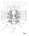
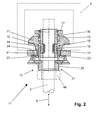
- FIGS. 1 and 2 is a tethering device 11 for a load adjustable threaded rod 5 for fixing to a component, shown here on a mounting rail 6.
- the mounting rail 6 has an extending in the longitudinal extent of the mounting rail 6 mounting opening 7, which is bounded by mutually spaced at a distance A edges 8.
- the tethering device 11 comprises a fastening element 31 for fixing the tethering device 11 to a component, wherein the fastening element 31 is designed as a rear engagement part for the areawise engagement of the edges 8 of the mounting rail 6 delimiting the mounting opening 7.
- the fastening element 31 advantageously has a length which is smaller than the distance A between the mounting opening 7 of the mounting rail 6 bounding edges 8 to each other, and a width B, which is greater than the distance A of the edges 8 of the mounting hole 7 to each other.
- the fastening element 31 is provided on two mutually opposite side edges, which come into engagement with the mounting rail 6 in the engagement state of the fastening element 31, with a profiling formed as a toothing.
- the tethering device 11 comprises an adjusting device 12 for the threaded rod 5, wherein the adjusting device 12 a rotatably mounted in the fastening element 31 sleeve member 13 with an internal thread, which is formed by two thread jaws 14, for the threaded rod 5 and at a first end portion 20 a radially Having protruding from the sleeve member 13 projection 17 for engaging behind the fastener 31 has.
- the internal thread forming threaded jaws 14 are mounted radially displaceable in the longitudinal axis 26 of the tether 11 in recesses 15 of the sleeve member 13 and spring-loaded by a threaded jaws 14 on the outside surrounding spring element 16 radially inwardly.
- the adjusting device 12 a rotatably connected to the sleeve member 13 and axially displaceable to this fixing means for fixing the threaded jaws 14 in the form of two blocking elements 23 which protrude from an adjusting member 21 in the direction of the fastening element 31.
- the blocking elements 23 are guided in an axial receptacle 19 in the sleeve member 13 and form the rotationally fixed connection between the Adjustment element 21 and the sleeve member 13 from.
- the fixing fix in a fixing position the threaded jaws 14 in an engaging in the thread of the threaded rod 5 position.
- a stop 24 facing the fastening element 31 is provided which limits the axial displaceability of the adjusting element 21 in the direction of the fastening element 31.
- a hexagonal formation is provided as a rotary handle 22 for a clamping tool.
- a spring element 36 for spring loading of the fastening element 31 in the direction of the adjusting element 21 is provided between the first end portion 20 of the sleeve member 13 circumferentially arranged projection 17 and the fastening element 31. Furthermore, the tethering device 11 between the fastening element 31 and the adjusting element 21 comprises a stop element 41 which can be brought into contact with the outside of the mounting rail 6.
- the fastening element 31 of the tethering device 11 which may be arranged on the threaded rod 5 before the assembly on the mounting rail 6, inserted at the desired location in the mounting rail 6 and the entire tethering device 11 about its longitudinal axis 26th rotated by about 90 °, so that the side edges of the fastener 31 engage behind the edges 8 of the mounting hole 7.
- the tying device 11 is self-lockingly displaceable along the mounting opening 7.
- the adjusting element 21 and thus the fixing means are in the, with reference to the drawing retracted release position (see Fig. 1 ), in which the blocking elements 23 do not limit the displaceability of the threaded jaws 14 radially outwards.
- the threaded rod 5 is inserted in the direction of arrow 4 in the arranged on the mounting rail 6 tether 11, wherein the threaded jaws 14 dodge radially outward (see double arrow 18 in Fig. 1 ). If there is no further displacement of the threaded rod 5 along the longitudinal axis 26, the threaded jaws 14 engage in the thread of the threaded rod 5 and secure the threaded rod 5 in the axial direction. Now the line to be fastened (not shown here) is inserted into the pipe clamp.
- the rotatably mounted in the fastening element 31 sleeve member 13 is rotated about the fixing means, wherein over the thread with the threaded rod 5 engaged threaded jaws 14 of the sleeve member 13, the threaded rod 5 according to the direction of rotation of the adjusting member 21 along the longitudinal axis 26th the tether 11 in the direction of the double arrow 9 is shifted toward the mounting rail 6 or away from it.
- This will be the Position of the arranged in the pipe clamp line perpendicular to the longitudinal direction of the component forming mounting rail 6 set.
- the adjusting element 21 and thus the fixing means is displaced axially in the direction of the fastening element 31 and thereby brought into the fixing position.
- the blocking elements 23 of the adjusting element 21 engage behind the threaded jaws 14 in the fixing position and secure them against dodging radially outwards.
- the fastener 31 facing the stop 24 on the adjusting element 21 limits the axial displacement of the adjusting element 21 in the direction of the fastening element 31.
- the threaded rod 5 is inserted before the arrangement of the tethering device 11 on the component in the tethering device 11 and this set simultaneously with the tethering device 11 on the component.
- the fixing means can be displaced axially in the direction of the fastening element 31 even before the fine adjustment of the threaded rod 5, since the fine adjustment can also take place in this position of the fixing means.
- a subsequent fine and coarse adjustment of the line is possible at any time with the tethering device 11 according to the invention with a loosened locknut 46.
Landscapes
- Engineering & Computer Science (AREA)
- General Engineering & Computer Science (AREA)
- Mechanical Engineering (AREA)
- Mutual Connection Of Rods And Tubes (AREA)
- Clamps And Clips (AREA)
Applications Claiming Priority (1)
| Application Number | Priority Date | Filing Date | Title |
|---|---|---|---|
| DE102007000387A DE102007000387A1 (de) | 2007-07-18 | 2007-07-18 | Anbindevorrichtung |
Publications (3)
| Publication Number | Publication Date |
|---|---|
| EP2017485A2 true EP2017485A2 (fr) | 2009-01-21 |
| EP2017485A3 EP2017485A3 (fr) | 2010-03-17 |
| EP2017485B1 EP2017485B1 (fr) | 2012-01-04 |
Family
ID=40042605
Family Applications (1)
| Application Number | Title | Priority Date | Filing Date |
|---|---|---|---|
| EP08104126A Not-in-force EP2017485B1 (fr) | 2007-07-18 | 2008-05-28 | Dispositif d'attache |
Country Status (4)
| Country | Link |
|---|---|
| EP (1) | EP2017485B1 (fr) |
| AT (1) | ATE540229T1 (fr) |
| DE (1) | DE102007000387A1 (fr) |
| ES (1) | ES2376497T3 (fr) |
Cited By (4)
| Publication number | Priority date | Publication date | Assignee | Title |
|---|---|---|---|---|
| EP3783234A1 (fr) | 2019-08-21 | 2021-02-24 | Hilti Aktiengesellschaft | Connecteur de tige filetée comportant un collier à rotation bloquée |
| EP3783235A1 (fr) | 2019-08-21 | 2021-02-24 | Hilti Aktiengesellschaft | Insert de connecteur avec trou de logement de tige |
| EP3783233A1 (fr) | 2019-08-21 | 2021-02-24 | Hilti Aktiengesellschaft | Connecteur de tige filetée avec bras de projection vers la bouche |
| WO2025257809A1 (fr) * | 2024-06-14 | 2025-12-18 | Eaton Intelligent Power Limited | Ensemble écrou à verrouillage rapide |
Citations (2)
| Publication number | Priority date | Publication date | Assignee | Title |
|---|---|---|---|---|
| EP0905425A2 (fr) | 1997-09-26 | 1999-03-31 | Wolfgang Halpaus | Dispositif de fixation |
| US20050238460A1 (en) | 2004-04-26 | 2005-10-27 | Feiyu Li | Quick coupling nut |
Family Cites Families (2)
| Publication number | Priority date | Publication date | Assignee | Title |
|---|---|---|---|---|
| DE3823000C2 (de) | 1988-07-07 | 1996-02-29 | Wolfgang Halpaus | Befestigungselement |
| DE10256861A1 (de) * | 2002-12-05 | 2004-06-24 | Hilti Ag | Befestigungssystem |
-
2007
- 2007-07-18 DE DE102007000387A patent/DE102007000387A1/de not_active Withdrawn
-
2008
- 2008-05-28 AT AT08104126T patent/ATE540229T1/de active
- 2008-05-28 ES ES08104126T patent/ES2376497T3/es active Active
- 2008-05-28 EP EP08104126A patent/EP2017485B1/fr not_active Not-in-force
Patent Citations (2)
| Publication number | Priority date | Publication date | Assignee | Title |
|---|---|---|---|---|
| EP0905425A2 (fr) | 1997-09-26 | 1999-03-31 | Wolfgang Halpaus | Dispositif de fixation |
| US20050238460A1 (en) | 2004-04-26 | 2005-10-27 | Feiyu Li | Quick coupling nut |
Cited By (10)
| Publication number | Priority date | Publication date | Assignee | Title |
|---|---|---|---|---|
| EP3783234A1 (fr) | 2019-08-21 | 2021-02-24 | Hilti Aktiengesellschaft | Connecteur de tige filetée comportant un collier à rotation bloquée |
| EP3783235A1 (fr) | 2019-08-21 | 2021-02-24 | Hilti Aktiengesellschaft | Insert de connecteur avec trou de logement de tige |
| EP3783233A1 (fr) | 2019-08-21 | 2021-02-24 | Hilti Aktiengesellschaft | Connecteur de tige filetée avec bras de projection vers la bouche |
| WO2021032527A1 (fr) | 2019-08-21 | 2021-02-25 | Hilti Aktiengesellschaft | Insert de raccord doté d'un trou de réception de tige |
| WO2021032536A1 (fr) | 2019-08-21 | 2021-02-25 | Hilti Aktiengesellschaft | Raccord de tige filetée doté d'un collier verrouillé en rotation |
| WO2021032517A1 (fr) | 2019-08-21 | 2021-02-25 | Hilti Aktiengesellschaft | Raccord de tige filetée muni de bras faisant saillie en direction d'une embouchure |
| US12146315B2 (en) | 2019-08-21 | 2024-11-19 | Hilti Aktiengesellschaft | Connector insert with rod accommodation hole |
| US12146520B2 (en) | 2019-08-21 | 2024-11-19 | Hilti Aktiengesellschaft | Threaded rod connector with mouthwardly projecting arms |
| US12247607B2 (en) | 2019-08-21 | 2025-03-11 | Hilti Aktiengesellschaft | Threaded rod connector with rotationally locked collar |
| WO2025257809A1 (fr) * | 2024-06-14 | 2025-12-18 | Eaton Intelligent Power Limited | Ensemble écrou à verrouillage rapide |
Also Published As
| Publication number | Publication date |
|---|---|
| EP2017485B1 (fr) | 2012-01-04 |
| EP2017485A3 (fr) | 2010-03-17 |
| DE102007000387A1 (de) | 2009-01-22 |
| ATE540229T1 (de) | 2012-01-15 |
| ES2376497T3 (es) | 2012-03-14 |
Similar Documents
| Publication | Publication Date | Title |
|---|---|---|
| EP2218924B1 (fr) | Dispositif de fixation destiné à l'agencement sur un rail de montage | |
| EP2765342B1 (fr) | Collier de serrage profilé avec pré-positionneur | |
| EP2435768B1 (fr) | Dispositif servant à fixer un rail de montage sur une tige filetée | |
| DE102011005598A1 (de) | Befestigungsvorrichtung zur Anordnung an einer Montageschiene | |
| AT512283B1 (de) | Solar-montagesystem | |
| EP2285623B1 (fr) | Fixation pour une pièce rapportée d un véhicule et dispositif pour tenir une pièce rapportée de véhicule | |
| EP3673181A1 (fr) | Système de vissage rapide, en particulier pour l'assemblage de modules en plusieurs parties | |
| EP3977903B1 (fr) | Élément de fixation, agencement de maintien et paroi de douche | |
| AT974U1 (de) | Verbindungsanordnung | |
| EP1396644A1 (fr) | Dispositif pour relier des rails d'assemblage | |
| EP2017485B1 (fr) | Dispositif d'attache | |
| DE202021107024U1 (de) | Verstellbarer Kabelbefestigungshalter | |
| EP2534386B1 (fr) | Attachement d'équipement avec des caractéristiques à haute fréquence telles que des convertisseurs d'impédance ou des amplificateurs à un corps de véhicule | |
| DE102009000702B4 (de) | Befestigungsvorrichtung zur Anordnung an einer Montageschiene | |
| DE202010015530U1 (de) | Einseitig einsetzbare Kabelverschraubung | |
| DE10208362B4 (de) | Vorrichtung zum Justieren eines Baukörpers und ein Justierverfahren | |
| DE102011110642B4 (de) | Beschlagbaugruppe | |
| EP2471686A1 (fr) | Tendeur à cliquet | |
| DE102017000481B4 (de) | Anbauteilejustiervorrichtung und Verfahren zum Justieren eines Anbauteils | |
| DE202007013500U1 (de) | Verbinder sowie Anordnung von zwei mit einem solchen Verbinder verbundenen Gegenständen | |
| EP2017484B1 (fr) | Dispositif d'attache | |
| DE102009000649A1 (de) | Befestigungsvorrichtung zur Anordnung an einer Montageschiene | |
| EP3356688A1 (fr) | Cheville à bascule | |
| DE102019008731A1 (de) | Schraubanordnung | |
| DE29621873U1 (de) | Montagesystem für die Anbringung eines Bauteils an einer C-förmigen Halteschiene sowie Drehwerkzeug dafür |
Legal Events
| Date | Code | Title | Description |
|---|---|---|---|
| PUAI | Public reference made under article 153(3) epc to a published international application that has entered the european phase |
Free format text: ORIGINAL CODE: 0009012 |
|
| AK | Designated contracting states |
Kind code of ref document: A2 Designated state(s): AT BE BG CH CY CZ DE DK EE ES FI FR GB GR HR HU IE IS IT LI LT LU LV MC MT NL NO PL PT RO SE SI SK TR |
|
| AX | Request for extension of the european patent |
Extension state: AL BA MK RS |
|
| PUAL | Search report despatched |
Free format text: ORIGINAL CODE: 0009013 |
|
| AK | Designated contracting states |
Kind code of ref document: A3 Designated state(s): AT BE BG CH CY CZ DE DK EE ES FI FR GB GR HR HU IE IS IT LI LT LU LV MC MT NL NO PL PT RO SE SI SK TR |
|
| AX | Request for extension of the european patent |
Extension state: AL BA MK RS |
|
| 17P | Request for examination filed |
Effective date: 20100917 |
|
| 17Q | First examination report despatched |
Effective date: 20101012 |
|
| AKX | Designation fees paid |
Designated state(s): AT BE BG CH CY CZ DE DK EE ES FI FR GB GR HR HU IE IS IT LI LT LU LV MC MT NL NO PL PT RO SE SI SK TR |
|
| GRAP | Despatch of communication of intention to grant a patent |
Free format text: ORIGINAL CODE: EPIDOSNIGR1 |
|
| GRAS | Grant fee paid |
Free format text: ORIGINAL CODE: EPIDOSNIGR3 |
|
| GRAA | (expected) grant |
Free format text: ORIGINAL CODE: 0009210 |
|
| AK | Designated contracting states |
Kind code of ref document: B1 Designated state(s): AT BE BG CH CY CZ DE DK EE ES FI FR GB GR HR HU IE IS IT LI LT LU LV MC MT NL NO PL PT RO SE SI SK TR |
|
| REG | Reference to a national code |
Ref country code: GB Ref legal event code: FG4D Free format text: NOT ENGLISH |
|
| REG | Reference to a national code |
Ref country code: CH Ref legal event code: EP |
|
| REG | Reference to a national code |
Ref country code: AT Ref legal event code: REF Ref document number: 540229 Country of ref document: AT Kind code of ref document: T Effective date: 20120115 |
|
| REG | Reference to a national code |
Ref country code: IE Ref legal event code: FG4D |
|
| REG | Reference to a national code |
Ref country code: DE Ref legal event code: R096 Ref document number: 502008006032 Country of ref document: DE Effective date: 20120308 |
|
| REG | Reference to a national code |
Ref country code: ES Ref legal event code: FG2A Ref document number: 2376497 Country of ref document: ES Kind code of ref document: T3 Effective date: 20120314 |
|
| REG | Reference to a national code |
Ref country code: NL Ref legal event code: VDEP Effective date: 20120104 |
|
| PG25 | Lapsed in a contracting state [announced via postgrant information from national office to epo] |
Ref country code: SI Free format text: LAPSE BECAUSE OF FAILURE TO SUBMIT A TRANSLATION OF THE DESCRIPTION OR TO PAY THE FEE WITHIN THE PRESCRIBED TIME-LIMIT Effective date: 20120104 |
|
| LTIE | Lt: invalidation of european patent or patent extension |
Effective date: 20120104 |
|
| PG25 | Lapsed in a contracting state [announced via postgrant information from national office to epo] |
Ref country code: IS Free format text: LAPSE BECAUSE OF FAILURE TO SUBMIT A TRANSLATION OF THE DESCRIPTION OR TO PAY THE FEE WITHIN THE PRESCRIBED TIME-LIMIT Effective date: 20120504 Ref country code: HR Free format text: LAPSE BECAUSE OF FAILURE TO SUBMIT A TRANSLATION OF THE DESCRIPTION OR TO PAY THE FEE WITHIN THE PRESCRIBED TIME-LIMIT Effective date: 20120104 Ref country code: NO Free format text: LAPSE BECAUSE OF FAILURE TO SUBMIT A TRANSLATION OF THE DESCRIPTION OR TO PAY THE FEE WITHIN THE PRESCRIBED TIME-LIMIT Effective date: 20120404 Ref country code: NL Free format text: LAPSE BECAUSE OF FAILURE TO SUBMIT A TRANSLATION OF THE DESCRIPTION OR TO PAY THE FEE WITHIN THE PRESCRIBED TIME-LIMIT Effective date: 20120104 Ref country code: LT Free format text: LAPSE BECAUSE OF FAILURE TO SUBMIT A TRANSLATION OF THE DESCRIPTION OR TO PAY THE FEE WITHIN THE PRESCRIBED TIME-LIMIT Effective date: 20120104 Ref country code: BG Free format text: LAPSE BECAUSE OF FAILURE TO SUBMIT A TRANSLATION OF THE DESCRIPTION OR TO PAY THE FEE WITHIN THE PRESCRIBED TIME-LIMIT Effective date: 20120404 |
|
| REG | Reference to a national code |
Ref country code: IE Ref legal event code: FD4D |
|
| PG25 | Lapsed in a contracting state [announced via postgrant information from national office to epo] |
Ref country code: PL Free format text: LAPSE BECAUSE OF FAILURE TO SUBMIT A TRANSLATION OF THE DESCRIPTION OR TO PAY THE FEE WITHIN THE PRESCRIBED TIME-LIMIT Effective date: 20120104 Ref country code: GR Free format text: LAPSE BECAUSE OF FAILURE TO SUBMIT A TRANSLATION OF THE DESCRIPTION OR TO PAY THE FEE WITHIN THE PRESCRIBED TIME-LIMIT Effective date: 20120405 Ref country code: PT Free format text: LAPSE BECAUSE OF FAILURE TO SUBMIT A TRANSLATION OF THE DESCRIPTION OR TO PAY THE FEE WITHIN THE PRESCRIBED TIME-LIMIT Effective date: 20120504 Ref country code: FI Free format text: LAPSE BECAUSE OF FAILURE TO SUBMIT A TRANSLATION OF THE DESCRIPTION OR TO PAY THE FEE WITHIN THE PRESCRIBED TIME-LIMIT Effective date: 20120104 Ref country code: LV Free format text: LAPSE BECAUSE OF FAILURE TO SUBMIT A TRANSLATION OF THE DESCRIPTION OR TO PAY THE FEE WITHIN THE PRESCRIBED TIME-LIMIT Effective date: 20120104 |
|
| PG25 | Lapsed in a contracting state [announced via postgrant information from national office to epo] |
Ref country code: CY Free format text: LAPSE BECAUSE OF FAILURE TO SUBMIT A TRANSLATION OF THE DESCRIPTION OR TO PAY THE FEE WITHIN THE PRESCRIBED TIME-LIMIT Effective date: 20120104 |
|
| PG25 | Lapsed in a contracting state [announced via postgrant information from national office to epo] |
Ref country code: EE Free format text: LAPSE BECAUSE OF FAILURE TO SUBMIT A TRANSLATION OF THE DESCRIPTION OR TO PAY THE FEE WITHIN THE PRESCRIBED TIME-LIMIT Effective date: 20120104 Ref country code: RO Free format text: LAPSE BECAUSE OF FAILURE TO SUBMIT A TRANSLATION OF THE DESCRIPTION OR TO PAY THE FEE WITHIN THE PRESCRIBED TIME-LIMIT Effective date: 20120104 Ref country code: CZ Free format text: LAPSE BECAUSE OF FAILURE TO SUBMIT A TRANSLATION OF THE DESCRIPTION OR TO PAY THE FEE WITHIN THE PRESCRIBED TIME-LIMIT Effective date: 20120104 Ref country code: DK Free format text: LAPSE BECAUSE OF FAILURE TO SUBMIT A TRANSLATION OF THE DESCRIPTION OR TO PAY THE FEE WITHIN THE PRESCRIBED TIME-LIMIT Effective date: 20120104 Ref country code: SE Free format text: LAPSE BECAUSE OF FAILURE TO SUBMIT A TRANSLATION OF THE DESCRIPTION OR TO PAY THE FEE WITHIN THE PRESCRIBED TIME-LIMIT Effective date: 20120104 Ref country code: IE Free format text: LAPSE BECAUSE OF FAILURE TO SUBMIT A TRANSLATION OF THE DESCRIPTION OR TO PAY THE FEE WITHIN THE PRESCRIBED TIME-LIMIT Effective date: 20120104 |
|
| PLBE | No opposition filed within time limit |
Free format text: ORIGINAL CODE: 0009261 |
|
| STAA | Information on the status of an ep patent application or granted ep patent |
Free format text: STATUS: NO OPPOSITION FILED WITHIN TIME LIMIT |
|
| BERE | Be: lapsed |
Owner name: HILTI AKTIENGESELLSCHAFT Effective date: 20120531 |
|
| PG25 | Lapsed in a contracting state [announced via postgrant information from national office to epo] |
Ref country code: SK Free format text: LAPSE BECAUSE OF FAILURE TO SUBMIT A TRANSLATION OF THE DESCRIPTION OR TO PAY THE FEE WITHIN THE PRESCRIBED TIME-LIMIT Effective date: 20120104 |
|
| 26N | No opposition filed |
Effective date: 20121005 |
|
| PG25 | Lapsed in a contracting state [announced via postgrant information from national office to epo] |
Ref country code: MC Free format text: LAPSE BECAUSE OF NON-PAYMENT OF DUE FEES Effective date: 20120531 |
|
| REG | Reference to a national code |
Ref country code: DE Ref legal event code: R097 Ref document number: 502008006032 Country of ref document: DE Effective date: 20121005 |
|
| PG25 | Lapsed in a contracting state [announced via postgrant information from national office to epo] |
Ref country code: BE Free format text: LAPSE BECAUSE OF NON-PAYMENT OF DUE FEES Effective date: 20120531 |
|
| PG25 | Lapsed in a contracting state [announced via postgrant information from national office to epo] |
Ref country code: MT Free format text: LAPSE BECAUSE OF FAILURE TO SUBMIT A TRANSLATION OF THE DESCRIPTION OR TO PAY THE FEE WITHIN THE PRESCRIBED TIME-LIMIT Effective date: 20120104 |
|
| PG25 | Lapsed in a contracting state [announced via postgrant information from national office to epo] |
Ref country code: LU Free format text: LAPSE BECAUSE OF NON-PAYMENT OF DUE FEES Effective date: 20120528 |
|
| PG25 | Lapsed in a contracting state [announced via postgrant information from national office to epo] |
Ref country code: HU Free format text: LAPSE BECAUSE OF FAILURE TO SUBMIT A TRANSLATION OF THE DESCRIPTION OR TO PAY THE FEE WITHIN THE PRESCRIBED TIME-LIMIT Effective date: 20080528 |
|
| PGFP | Annual fee paid to national office [announced via postgrant information from national office to epo] |
Ref country code: GB Payment date: 20140528 Year of fee payment: 7 |
|
| PGFP | Annual fee paid to national office [announced via postgrant information from national office to epo] |
Ref country code: AT Payment date: 20140428 Year of fee payment: 7 Ref country code: TR Payment date: 20140430 Year of fee payment: 7 Ref country code: CH Payment date: 20140513 Year of fee payment: 7 Ref country code: IT Payment date: 20140522 Year of fee payment: 7 Ref country code: ES Payment date: 20140411 Year of fee payment: 7 Ref country code: FR Payment date: 20140509 Year of fee payment: 7 |
|
| REG | Reference to a national code |
Ref country code: CH Ref legal event code: PL |
|
| REG | Reference to a national code |
Ref country code: AT Ref legal event code: MM01 Ref document number: 540229 Country of ref document: AT Kind code of ref document: T Effective date: 20150528 |
|
| GBPC | Gb: european patent ceased through non-payment of renewal fee |
Effective date: 20150528 |
|
| PG25 | Lapsed in a contracting state [announced via postgrant information from national office to epo] |
Ref country code: CH Free format text: LAPSE BECAUSE OF NON-PAYMENT OF DUE FEES Effective date: 20150531 Ref country code: LI Free format text: LAPSE BECAUSE OF NON-PAYMENT OF DUE FEES Effective date: 20150531 Ref country code: IT Free format text: LAPSE BECAUSE OF NON-PAYMENT OF DUE FEES Effective date: 20150528 |
|
| REG | Reference to a national code |
Ref country code: FR Ref legal event code: ST Effective date: 20160129 |
|
| PG25 | Lapsed in a contracting state [announced via postgrant information from national office to epo] |
Ref country code: AT Free format text: LAPSE BECAUSE OF NON-PAYMENT OF DUE FEES Effective date: 20150528 |
|
| PG25 | Lapsed in a contracting state [announced via postgrant information from national office to epo] |
Ref country code: GB Free format text: LAPSE BECAUSE OF NON-PAYMENT OF DUE FEES Effective date: 20150528 |
|
| PG25 | Lapsed in a contracting state [announced via postgrant information from national office to epo] |
Ref country code: FR Free format text: LAPSE BECAUSE OF NON-PAYMENT OF DUE FEES Effective date: 20150601 |
|
| REG | Reference to a national code |
Ref country code: ES Ref legal event code: FD2A Effective date: 20160627 |
|
| PG25 | Lapsed in a contracting state [announced via postgrant information from national office to epo] |
Ref country code: ES Free format text: LAPSE BECAUSE OF NON-PAYMENT OF DUE FEES Effective date: 20150529 |
|
| PG25 | Lapsed in a contracting state [announced via postgrant information from national office to epo] |
Ref country code: TR Free format text: LAPSE BECAUSE OF NON-PAYMENT OF DUE FEES Effective date: 20150528 |
|
| PGFP | Annual fee paid to national office [announced via postgrant information from national office to epo] |
Ref country code: DE Payment date: 20230519 Year of fee payment: 16 |
|
| REG | Reference to a national code |
Ref country code: DE Ref legal event code: R119 Ref document number: 502008006032 Country of ref document: DE |
|
| PG25 | Lapsed in a contracting state [announced via postgrant information from national office to epo] |
Ref country code: DE Free format text: LAPSE BECAUSE OF NON-PAYMENT OF DUE FEES Effective date: 20241203 |