EP2017510B1 - Vanne à papillon pour gaz - Google Patents
Vanne à papillon pour gaz Download PDFInfo
- Publication number
- EP2017510B1 EP2017510B1 EP07011448A EP07011448A EP2017510B1 EP 2017510 B1 EP2017510 B1 EP 2017510B1 EP 07011448 A EP07011448 A EP 07011448A EP 07011448 A EP07011448 A EP 07011448A EP 2017510 B1 EP2017510 B1 EP 2017510B1
- Authority
- EP
- European Patent Office
- Prior art keywords
- carter
- spring
- valve
- valve according
- flap
- Prior art date
- Legal status (The legal status is an assumption and is not a legal conclusion. Google has not performed a legal analysis and makes no representation as to the accuracy of the status listed.)
- Not-in-force
Links
Images






Classifications
-
- F—MECHANICAL ENGINEERING; LIGHTING; HEATING; WEAPONS; BLASTING
- F16—ENGINEERING ELEMENTS AND UNITS; GENERAL MEASURES FOR PRODUCING AND MAINTAINING EFFECTIVE FUNCTIONING OF MACHINES OR INSTALLATIONS; THERMAL INSULATION IN GENERAL
- F16K—VALVES; TAPS; COCKS; ACTUATING-FLOATS; DEVICES FOR VENTING OR AERATING
- F16K1/00—Lift valves or globe valves, i.e. cut-off apparatus with closure members having at least a component of their opening and closing motion perpendicular to the closing faces
- F16K1/16—Lift valves or globe valves, i.e. cut-off apparatus with closure members having at least a component of their opening and closing motion perpendicular to the closing faces with pivoted closure-members
- F16K1/18—Lift valves or globe valves, i.e. cut-off apparatus with closure members having at least a component of their opening and closing motion perpendicular to the closing faces with pivoted closure-members with pivoted discs or flaps
- F16K1/22—Lift valves or globe valves, i.e. cut-off apparatus with closure members having at least a component of their opening and closing motion perpendicular to the closing faces with pivoted closure-members with pivoted discs or flaps with axis of rotation crossing the valve member, e.g. butterfly valves
-
- F—MECHANICAL ENGINEERING; LIGHTING; HEATING; WEAPONS; BLASTING
- F02—COMBUSTION ENGINES; HOT-GAS OR COMBUSTION-PRODUCT ENGINE PLANTS
- F02B—INTERNAL-COMBUSTION PISTON ENGINES; COMBUSTION ENGINES IN GENERAL
- F02B29/00—Engines characterised by provision for charging or scavenging not provided for in groups F02B25/00, F02B27/00 or F02B33/00 - F02B39/00; Details thereof
- F02B29/08—Modifying distribution valve timing for charging purposes
- F02B29/083—Cyclically operated valves disposed upstream of the cylinder intake valve, controlled by external means
-
- F—MECHANICAL ENGINEERING; LIGHTING; HEATING; WEAPONS; BLASTING
- F02—COMBUSTION ENGINES; HOT-GAS OR COMBUSTION-PRODUCT ENGINE PLANTS
- F02D—CONTROLLING COMBUSTION ENGINES
- F02D9/00—Controlling engines by throttling air or fuel-and-air induction conduits or exhaust conduits
- F02D9/08—Throttle valves specially adapted therefor; Arrangements of such valves in conduits
- F02D9/10—Throttle valves specially adapted therefor; Arrangements of such valves in conduits having pivotally-mounted flaps
- F02D9/1065—Mechanical control linkage between an actuator and the flap, e.g. including levers, gears, springs, clutches, limit stops of the like
-
- F—MECHANICAL ENGINEERING; LIGHTING; HEATING; WEAPONS; BLASTING
- F16—ENGINEERING ELEMENTS AND UNITS; GENERAL MEASURES FOR PRODUCING AND MAINTAINING EFFECTIVE FUNCTIONING OF MACHINES OR INSTALLATIONS; THERMAL INSULATION IN GENERAL
- F16K—VALVES; TAPS; COCKS; ACTUATING-FLOATS; DEVICES FOR VENTING OR AERATING
- F16K27/00—Construction of housing; Use of materials therefor
- F16K27/02—Construction of housing; Use of materials therefor of lift valves
- F16K27/0209—Check valves or pivoted valves
- F16K27/0218—Butterfly valves
-
- F—MECHANICAL ENGINEERING; LIGHTING; HEATING; WEAPONS; BLASTING
- F16—ENGINEERING ELEMENTS AND UNITS; GENERAL MEASURES FOR PRODUCING AND MAINTAINING EFFECTIVE FUNCTIONING OF MACHINES OR INSTALLATIONS; THERMAL INSULATION IN GENERAL
- F16K—VALVES; TAPS; COCKS; ACTUATING-FLOATS; DEVICES FOR VENTING OR AERATING
- F16K27/00—Construction of housing; Use of materials therefor
- F16K27/02—Construction of housing; Use of materials therefor of lift valves
- F16K27/029—Electromagnetically actuated valves
-
- F—MECHANICAL ENGINEERING; LIGHTING; HEATING; WEAPONS; BLASTING
- F02—COMBUSTION ENGINES; HOT-GAS OR COMBUSTION-PRODUCT ENGINE PLANTS
- F02D—CONTROLLING COMBUSTION ENGINES
- F02D9/00—Controlling engines by throttling air or fuel-and-air induction conduits or exhaust conduits
- F02D9/02—Controlling engines by throttling air or fuel-and-air induction conduits or exhaust conduits concerning induction conduits
- F02D2009/0201—Arrangements; Control features; Details thereof
- F02D2009/0269—Throttle closing springs; Acting of throttle closing springs on the throttle shaft
-
- Y—GENERAL TAGGING OF NEW TECHNOLOGICAL DEVELOPMENTS; GENERAL TAGGING OF CROSS-SECTIONAL TECHNOLOGIES SPANNING OVER SEVERAL SECTIONS OF THE IPC; TECHNICAL SUBJECTS COVERED BY FORMER USPC CROSS-REFERENCE ART COLLECTIONS [XRACs] AND DIGESTS
- Y02—TECHNOLOGIES OR APPLICATIONS FOR MITIGATION OR ADAPTATION AGAINST CLIMATE CHANGE
- Y02T—CLIMATE CHANGE MITIGATION TECHNOLOGIES RELATED TO TRANSPORTATION
- Y02T10/00—Road transport of goods or passengers
- Y02T10/10—Internal combustion engine [ICE] based vehicles
- Y02T10/12—Improving ICE efficiencies
Definitions
- the invention relates to a rotary valve for guiding gas, in particular for use in a fresh gas or exhaust pipe of a heat engine, with a drive, a shaft pivotally mounted in a housing and a rotary shaft connected to the shaft for closing and opening a channel cross-section of the housing the formed rotary valve shaft composite is designed as drivable by means of the drive oscillator and serves as an energy storage at least one spring.
- Rotary butterfly valves are increasingly used in fresh gas and exhaust pipes of heat engines to control the gas mass flow.
- Swirl valves which are designed as oscillating oscillator, can reach very high clock frequencies over 200 hertz. These switching frequencies allow, for. B. when changing the gas of internal combustion engines, the butterfly valve one or more times during a work cycle to open or close. This results in a high degree of freedom of movement in the design of the charge cycle.
- the use of oscillating butterfly valves in the fresh gas range, in the exhaust gas area and on mixing lines of fresh and exhaust pipes makes sense.
- the number of butterfly valves in the fresh gas range may vary. It is possible for each inlet valve to provide a butterfly valve, to use a butterfly valve per cylinder or to supply several cylinders via a butterfly valve.
- a butterfly valve of the type mentioned, which is used in a fresh gas line of a heat engine is known from the magazine MTZ, 12/2001, pages 998 to 1009 under the title "Impulse charging and load control of reciprocating engines by an air cycle valve".
- There is described under 4. a prototype for engine tests and illustrated in Figure 4, in which the natural frequency of the oscillatory spring-mass system is determined by an accommodated in the armature shaft torsion spring and the moments of inertia of a pivot armature and a flap.
- the movement of the oscillating system is controlled by two independently switchable Umledgehubmagnete, between which the pivot armature oscillates spring assisted.
- butterfly valves especially for fresh air side use, are from DE 103 19 168 A1 as well as out ATZIMTZ textbook, "Gasoline engine with direct injection”, special air pressure valve, ISBN 978-3-8348-0202-6, published in April 2007 known.
- valve types discussed have the disadvantage of a large axial height. Starting from a necessary flow cross-section in the valve region of the valve, which must correspond at least to the channel cross-section on the cylinder head, it can be seen that a coaxial connection of the valves to cylinder heads of in-line engines is hardly possible with regard to the cylinder spacings customary today. Also, the use of torsion springs of circular cross-section hampers a short axial design, since practical spring return torques and torsion angles can only be achieved with spring lengths that exceed the cylinder spacing.
- an upward electromagnetic drive may increase the engine height inadmissible, which is to be considered in passenger car front engines in terms of the required crumple zone between the engine and hood.
- thermodynamic advantages can be achieved with fresh gas side valves by the arrangement of at least one rotary valve per cylinder close to the engine intake valves implement.
- the axial Length of the rotary valve at the required flow cross sections may be smaller than the cylinder spacing, to allow an advantageous coaxial arrangement of the butterfly valves on the cylinder head.
- a butterfly valve of this kind is from the DE 103 24 398 A1 known.
- the object is achieved in a rotary valve of the type mentioned fact that the spring is at least partially in the gas-carrying interior of the valve housing.
- the spring may well be completely in the gas-carrying interior of the housing.
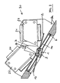
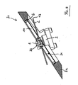
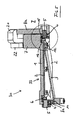
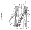
- a rotary flap 2 On the rotatable shaft 1, a rotary flap 2 is fixed, which can rotate together in a housing 8 via at least two bearing points 10.
- the housing 8 has at least the housing support 8a, which is flat in the exemplary embodiment, and can additionally be fitted in the housing support 8a FIGS. 9 to 14 shown, connected to the housing support 8a elements 24, 25 of the connected line system, in particular the connected intake system exhibit.
- the interior of the housing 8 or housing support 8a in this case represents the gas-carrying interior 31 of the valve 30.
- a spring 3 is fastened with a spring end 12 to the rotary flap shaft composite 33 formed by the rotary flap 2 and the shaft 1 and connected to the housing support 8a at the other end of the spring.
- the spring 3 undergoes a deformation which leads to a corresponding spring return torque.
- the rotational movement of the rotary valve shaft assembly 33 is limited in both directions, wherein advantageously the maximum rotational deflections, the closed position and the open position of the rotary valve 30 are assigned.
- the sealing of the valve 30 in the closed position advantageously produces a gap seal formed by the circular outer circumferential surface 13 of the flap 2 and the inner wall of the housing support 8a.
- sealing ring 6 Due to the necessary in practice very narrow gap of a few 1/100 mm between the outer peripheral surface 13 of the flap 2 and the housing support 8a with respect to the usual manufacturing tolerances of all components and the bearing clearances, which in total often exceed the sealing gap height is in the housing support 8a in the Closed position of the valve 30, a sealing ring 6 is inserted.
- the sealing ring 6 is advantageously secured in an open groove 15 of the housing support 8a by a clamping ring 9 against axial displacement. This sealing ring 6 forms with its inner peripheral surface 14 and the outer peripheral surface 13 of the flap 2 the required sealing gap.
- the afflicted with radial play in the housing support 8a sealing ring 6 is centered during the assembly of the valve 30 in the closed position on the flap 2 and thus finds its position in the housing support 8a under equalization of all position tolerances.
- the sealing ring 6 on the one hand in the housing support 8a in the groove 15 remain radially free to move, since the flap 2 is able to center the sealing ring 6 again at each closing operation.
- the sealing ring 6 seals with its side surfaces 16 to the housing support 8a, for example, by system sealing.
- the sealing ring 6 can be firmly connected and sealed by the flap 2 to the housing 8, which can be achieved, for example, by gluing and / or pressing.
- the materials of flap 2 and sealing ring 6 should have similar coefficients of thermal expansion in order to subject the sealing gap height over the operating temperature range of the valve 30 to slight fluctuations. In this context, on the EP 1 498 596 B1 directed.
- the spring 3 may be made of corrosion resistant material such as stainless steel, bronze, nimonic, fiber composites, etc.
- a particularly advantageous spring design is the leaf spring shown in the embodiment 3.
- the leaf spring undergoes a torsional bending stress under deformation, which allows a significant reduction of the axial length of the spring compared to concentric torsion springs with approximately circular cross-section, under the condition identical Torsion angle, materials and maximum stresses.
- the shape of the spring ie its profile profile and curvature or setting can be made very permissive to accommodate simultaneously occurring torsional and bending stresses, without exceeding the maximum material stresses.
- the spring 3 can be inexpensively cut to length from strip steel and pressed into shape.
- the flat design of the leaf spring minimizes their flow resistance in the channel and allows the use of a low-cost planar rotary valve 2, which is preferably stamped or cut from lightweight materials such as fiber composites, plastics or even metals, for example sheet material can be.
- the leaf spring geometry in conjunction with a flat rotary flap 2 can easily be screwed or riveted to the wave 1 held flat in the channel region of the valve 30. This is a significant advantage over rotary valve designs with a concentric jacketed torsion bar which requires a costly hollow shaft, does not provide a flat surface on the flap mounting shaft, and requires a flap curl or break near the axle to rotate the torsion bar.
- the geometry of the outer peripheral surface 13 of the flap 2 or the inner peripheral surface 14 of the sealing ring 6 / housing inner surface can be arbitrarily shaped, since the sealing effect of the formed sealing gap is independent of its curvature.
- the formation of the flap 2 with a circular outer peripheral surface 13 is advantageous since it can be inexpensively turned, fitted, honed, etc. onto a fit.
- the manufacturing cost per flap can be significantly reduced.
- Corresponding cost savings can be implemented in the manufacture of the sealing ring 6, when the sealing ring is tapped from a long pipe previously turned in its inner peripheral surface 14 to fit, drilled, honed, etc., since the costly finishing of the sealing surface are transferred to a plurality of sealing rings can.
- the bearings 10 may consist of rolling or plain bearings.
- the storage can be carried out very cost-effectively by bearing pin 5 compressed in the housing support 8a and by sliding bearing 4 pressed into the shaft 1.
- the sliding bearing designed as a dry sliding bearing, further has advantages in terms of waiving any storage seal.
- the proportion of exhaust gas to the fresh gas which is frequently mixed in modern internal combustion engines, can positively influence the lubrication of the bearing points with its constituents, such as soot (carbon) and condensate.
- the gas-conducting region of the valve 30 can be designed in several parts.
- the flat feasibility of the housing support allows easy accessibility for the assembly of the individual components to be mounted on this. With the housing support 8a, as shown in the embodiment, channel fittings 24, 25 are gas-tight, form part of the housing 8 and make the gas guide to the housing support 8a out or away from this leading and also record or integrate the drive of the valve 30 can.
- the flap 2 thus opens the channel cross section only at a later time of their movement, but then with a higher angular velocity.
- This effect of a feedforward control which runs mirror-inverted during the closing operation for the opening process, slightly reduces the flow cross-section at a given flap rotation angle, but significantly reduces the time to release the remaining entire cross-section.
- Closing time span of the valve can be significantly shortened, whereby the time cross-sections of the valve when opening and closing grow accordingly.
- the drive of the rotary valve 30 can be done mechanically, pneumatically, hydraulically and also electromagnetically or in combination above mentioned drive options.
- the drive acts on the shaft 1 or on an extension of the shaft 1, not shown here.
- an electromagnetic drive 32 is designed via two electromagnets 18, 19, which act on an armature 7 connected to the shaft 1 and the armature 7, Depending on the energization of the electromagnets 18 and 19, tighten until it touches the pole face of a respective magnet.
- the electromagnets 18, 19 can be inexpensively manufactured as U-magnets and have ferromagnetic stators 22, 23 with deferred coils 20, 21. To reduce eddy currents in the magnetic field change, the stators 22, 23 of stacked, mutually insulated sheets build.
- the armature 7 is also made of ferromagnetic material and can advantageously be made in one piece with the shaft 1 made of steel. Shaft / anchor production can be cost-effective in cast, extrusion or sintering technology, etc.
- Shaft / anchor production can be cost-effective in cast, extrusion or sintering technology, etc.
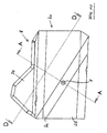
- the force of the electromagnets 18, 19 can be changed to the armature 7, according to a characteristic influencing, as illustrated by the contour 26 of the stator 22. This makes it possible, with simultaneous energization of all coils and armature position in the zero position (spring relaxed) to pull the armature in a preferred direction.
- the advantage of such an asymmetry of the force effect is, on the one hand, that the armature 7 does not necessarily have to oscillate at resonant frequency at the start of the valve 30 in order to reach an end position on a stator, but to be able to attract the armature 7 directly to a stator by virtue of excess torque.
- stop afflicted electromagnetic actuators with identical magnetic field energy higher holding forces between armature 7 and stators 22, 23 as stop-free actuators that leave an air gap between the armature and stator.
- the advantage of the non-impact actuators lies in the lower noise and the freedom from wear of the armature and stator. If valves are designed for the highest switching frequencies, it is preferable to use a drive with a stop. Both impact and non-impact drives can be used for the valve 30.
- a further reduction in space of the valve 30 results from the integration of the armature 7 and the electromagnets 18 and 19 in the gas-carrying interior 31 of the housing 8.
- the electromagnetic drive 32 is fluidly admitted into the channel wall of the housing 8, but is in direct contact with the gas flowing through the valve.
- the channel fittings 24, 25 also take the gas-tight encapsulation of the electromagnetic drive 32 to the outside.
- the integrated in the gas-conducting interior 31 electromagnetic drive 32 has thus advantages in terms of a space requirement, lower friction (elimination of additional bearing seals) and the acoustic enclosure through the housing 8 / housing support 8a of the valve 30, the housing 8 must be made gas-tight anyway and reasons of strength and appropriate wall thicknesses for connection to the engine or
- the suction module should have, which can largely prevent a caused by the electromagnetic drive 32 structure-borne sound excitation.
Landscapes
- Engineering & Computer Science (AREA)
- General Engineering & Computer Science (AREA)
- Mechanical Engineering (AREA)
- Chemical & Material Sciences (AREA)
- Combustion & Propulsion (AREA)
- Physics & Mathematics (AREA)
- Electromagnetism (AREA)
- Lift Valve (AREA)
Claims (21)
- Vanne papillon (30) pour le transport de gaz, en particulier pour une utilisation dans un tuyau de gaz frais ou le tuyau d'échappement d'un moteur thermique, dotée d'un entraînement (32), d'un arbre (1) pivotant logé dans un boîtier (8) et un papillon (2) relié à l'arbre (1) pour la fermeture et l'ouverture d'une section transversale du canal du boîtier (8), l'ensemble papillon-arbre (33) constitué comme un oscillateur entraînable à l'aide de l'entraînement (32) dans lequel au moins un ressort (3) sert d'accumulateur d'énergie, et un espace intérieur transporteur de gaz (31) étant formé par le boîtier (8), caractérisée en ce que le ressort (3) se trouve au moins partiellement dans l'espace intérieur transporteur de gaz (31) du boîtier (8).
- Valve selon la revendication 1, caractérisée en ce que le ressort (3) se trouve entièrement dans l'espace intérieur transporteur de gaz (31) du boîtier (8).
- Valve selon la revendication 1, caractérisée en ce que le boîtier (8) est formé au moyen d'un support de boîtier (8a) qui héberge l'ensemble papillon-arbre (33), ou formé au moyen du support de boîtier (8a) et au moins d'un tuyau transporteur de gaz (24, 25) qui lui est connecté.
- Valve selon les revendications de 1 à 3, caractérisée en ce que le ressort (3) est conçu comme un ressort de torsion ou comme un ressort de flexion hélicoïdal.
- Valve selon l'une des revendications de 1 à 4, caractérisée en ce que le ressort (3) est fixé par une extrémité de ressort (12) à l'ensemble papillon-arbre (33) et relié par l'autre extrémité du ressort (11) au boîtier (8), en particulier au support de boîtier (8a).
- Valve selon la revendication 5, caractérisée en ce que le centre de gravité de l'extrémité du ressort (12), dans la zone duquel le ressort (3) est fixé à l'ensemble papillon-arbre (33), coupe l'axe de rotation de l'arbre (1) ou plus exactement est situé près de ce dernier et l'extrémité de ressort (11), dans la zone de laquelle le ressort (3) est relié avec le boîtier (8), en particulier avec le support du boîtier (8a), est par son centre de gravité plus éloignée de l'axe de rotation que l'extrémité du ressort (12) dans la zone de laquelle le ressort (3) est fixé à l'ensemble papillon-arbre (33).
- Valve selon l'une des revendications de 1 à 6, caractérisée en ce que le ressort (3) est construit comme un ressort à lames.
- Valve selon l'une des revendications de 1 à 7, caractérisée en ce que le ressort (3) présente une section transversale de ressort variable et/ou le profil de la section transversale de ressort est construit rectangulaire, elliptique ou polygonal et/ou le ressort (3) est dévié dans lui-même ou bien tordu.
- Valve selon l'une des revendications de 1 à 8, caractérisée en ce que dans l'état de fermeture de la valve (30), le clapet (2) forme avec la surface de son périmètre extérieur (13) et la paroi intérieure du boîtier une étroite fente d'étranglement.
- Valve selon l'une des revendications de 1 à 7, caractérisée en ce que dans l'état de fermeture de la valve (30), le clapet (2) forme entre la surface du périmètre extérieur (13) et la surface du périmètre intérieur d'un anneau d'étanchéité (6) une étroite fente d'étranglement, l'anneau d'étanchéité (6) étant encastré de manière fixe ou mobile dans le boîtier (8), en particulier dans le support du boîtier (8a) de sorte qu' il y ait également étanchéité par rapport à ce dernier.
- Valve selon l'une des revendications de 1 à 10, caractérisée en ce que le clapet (2) est plat et la surface du périmètre extérieur (13) du clapet (2) a une forme circulaire.
- Valve selon l'une des revendications de 1 à 11, caractérisée en ce que le ressort (3) ne coupe pas ou n'interrompt pas un jeu d'étanchéité entre clapet (2) et boîtier (8), en particulier support du boîtier (8a), plus exactement anneau d'étanchéité (6).
- Valve selon l'une des revendications de 1 à 12, caractérisée en ce que le clapet (2) est fixé sur l'arbre (1) dans une position de sorte qu'en cas d'écart de pression au niveau de la valve fermée (30) il n'y ait pas de transmission de couple de force du clapet (2) à l'arbre (1).
- Valve selon l'une des revendications de 1 à 13, caractérisée en ce que le clapet (2) et l'arbre (1) sont réalisés d'une seule pièce.
- Valve selon l'une des revendications de 1 à 14, caractérisée en ce que dans la zone de position de fermeture de la valve (30), le contour intérieur du boîtier (8), en particulier du support du boîtier (8a), c'est-à-dire la surface du périmètre intérieur (14) de l'anneau d'étanchéité (6) s'appuie contre la trajectoire des mouvements circulaires de la surface du périmètre extérieur(13) du clapet (2) et ainsi réduit fortement la fente d'ouverture entre clapet (2) et boîtier (8), en particulier le support du boîtier (8a), c'est-à-dire le clapet (2) et l'anneau d'étanchéité (6) près de la zone en position de fermeture.
- Valve selon la revendication 15, caractérisée en ce que le support de boîtier (8) héberge les logements (10) de l'ensemble papillon-arbre (33) et de l'anneau d'étanchéité (6).
- Valve selon l'une des revendications de 1 à 16, caractérisée en ce que le fonctionnement de l'oscillateur est électromagnétique.
- Valve selon la revendication 16, caractérisée en ce que l'entraînement électromagnétique (32) se trouve entièrement ou partiellement dans l'espace intérieur transporteur de gaz (31) de la valve (9).
- Valve selon la revendication 17 ou 18, caractérisée en ce que l'entraînement électromagnétique (32) est composé de deux électroaimants (18, 19) et d'un rotor ferromagnétique (7) reliée à l'ensemble papillon-arbre (33), le rotor (7) étant attir é tour à tour par les électroaimants (18, 19).
- Valve selon la revendication 19, caractérisée en ce que le rotor (7) et l'arbre (1) sont fabriqués d'une seule pièce en matériau ferromagnétique.
- Valve selon la revendication 16 ou 17, caractérisée en ce que les électroaimants (18, 19) sont formés de sorte qu'ils exercent, en position de ressort détendu (3) dans le cas de l'alimentation électrique commune des électroaimants (18, 19), un couple de force asymétrique sur le rotor (7) et ainsi tirent le rotor (7) dans la direction d'un aimant préférentiel correspondant à une influence sur les caractéristiques (26).
Priority Applications (2)
| Application Number | Priority Date | Filing Date | Title |
|---|---|---|---|
| DE502007006777T DE502007006777D1 (de) | 2007-06-12 | 2007-06-12 | Gasführendes Drehklappenventil |
| EP07011448A EP2017510B1 (fr) | 2007-06-12 | 2007-06-12 | Vanne à papillon pour gaz |
Applications Claiming Priority (1)
| Application Number | Priority Date | Filing Date | Title |
|---|---|---|---|
| EP07011448A EP2017510B1 (fr) | 2007-06-12 | 2007-06-12 | Vanne à papillon pour gaz |
Publications (2)
| Publication Number | Publication Date |
|---|---|
| EP2017510A1 EP2017510A1 (fr) | 2009-01-21 |
| EP2017510B1 true EP2017510B1 (fr) | 2011-03-23 |
Family
ID=38627035
Family Applications (1)
| Application Number | Title | Priority Date | Filing Date |
|---|---|---|---|
| EP07011448A Not-in-force EP2017510B1 (fr) | 2007-06-12 | 2007-06-12 | Vanne à papillon pour gaz |
Country Status (2)
| Country | Link |
|---|---|
| EP (1) | EP2017510B1 (fr) |
| DE (1) | DE502007006777D1 (fr) |
Cited By (1)
| Publication number | Priority date | Publication date | Assignee | Title |
|---|---|---|---|---|
| CN104632423A (zh) * | 2013-11-13 | 2015-05-20 | 马勒国际有限公司 | 用于内燃机的新鲜空气系统 |
Families Citing this family (1)
| Publication number | Priority date | Publication date | Assignee | Title |
|---|---|---|---|---|
| DE102015118001A1 (de) * | 2015-10-22 | 2017-04-27 | Vag-Armaturen Gmbh | Absperrarmaturengehäuse |
Family Cites Families (6)
| Publication number | Priority date | Publication date | Assignee | Title |
|---|---|---|---|---|
| DE2718821C2 (de) | 1977-04-28 | 1979-02-22 | Gustav F. Gerdts Kg, 2800 Bremen | Rückschlagklappe |
| DE10319168A1 (de) | 2003-04-29 | 2004-12-02 | Lsp Innovative Automotive Systems Gmbh | Im Saugrohr eines Hubkolbenmotors wirksames Lufttaktventil |
| DE10320743A1 (de) * | 2003-05-09 | 2004-12-16 | Daimlerchrysler Ag | Vorrichtung zur Steuerung der Strömung in einem gasführenden Kanal |
| DE10324398A1 (de) * | 2003-05-28 | 2004-12-23 | Schatz Thermo Engineering | Hochgeschwindigkeitsstelleinrichtung |
| EP1498596B1 (fr) * | 2003-07-17 | 2006-10-18 | Arno Hofmann | Joint d'étanchéité à fente étrangleur pour soupapes |
| JP4575049B2 (ja) * | 2004-07-02 | 2010-11-04 | 三菱電機株式会社 | エンジン用吸気量制御装置 |
-
2007
- 2007-06-12 DE DE502007006777T patent/DE502007006777D1/de active Active
- 2007-06-12 EP EP07011448A patent/EP2017510B1/fr not_active Not-in-force
Cited By (2)
| Publication number | Priority date | Publication date | Assignee | Title |
|---|---|---|---|---|
| CN104632423A (zh) * | 2013-11-13 | 2015-05-20 | 马勒国际有限公司 | 用于内燃机的新鲜空气系统 |
| CN104632423B (zh) * | 2013-11-13 | 2018-10-16 | 马勒国际有限公司 | 用于内燃机的新鲜空气系统 |
Also Published As
| Publication number | Publication date |
|---|---|
| DE502007006777D1 (de) | 2011-05-05 |
| EP2017510A1 (fr) | 2009-01-21 |
Similar Documents
| Publication | Publication Date | Title |
|---|---|---|
| EP1095210B1 (fr) | Dispositif de commande de charge et procede pour assurer la commande d'un moteur a combustion interne a piston alternatif | |
| EP0303649B1 (fr) | Machine a piston oscillant | |
| EP3087262B1 (fr) | Procédé pour faire fonctionner un moteur à combustion interne et moteur à combustion interne permettant de mettre en oeuvre ce procédé | |
| EP3455477B1 (fr) | Turbine pour une turbocompresseur avec un carter deux volutes et agencement de vanne pour la connection des deux volutes et contrôle de vanne de décharge | |
| DE102009048125B4 (de) | Wastegate-Anordnung für eine Turbine, Turbine für einen Abgasturbolader, Abgasturbolader für ein Kraftfahrzeug und Verfahren zum Betreiben eines Abgasturboladers | |
| WO1996022453A1 (fr) | Moteur | |
| WO2008052738A1 (fr) | Turbocompresseur de gaz d'échappement utilisé pour un moteur à combustion interne | |
| EP1281845A2 (fr) | Soupape de commande additionnelle dans le conduit d'admission d'un moteur à combustion interne | |
| EP1420152A2 (fr) | Turbosoufflante | |
| DE102012209562B4 (de) | Turbinengehäuse für einen Abgasturbolader | |
| DE102009050975A1 (de) | Leitvorrichtung für einen Abgasturbolader mit verstellbarer Turbinengeometrie sowie Abgasturbolader für eine Brennkraftmaschine | |
| EP2017510A1 (fr) | Vanne à écluse rotative écoulant de gaz | |
| EP2003308B1 (fr) | Vanne à papillon | |
| DE102012022942A1 (de) | Verbrennungskraftmaschine für einen Kraftwagen | |
| EP2133538B1 (fr) | Vanne à papillon dotée d'un ressort de torsion | |
| DE102010013367A1 (de) | Abgaskrümmer-Turbolader-Anordnung für eine Kraftfahrzeug-Brennkraftmaschine | |
| DE10327603A1 (de) | Medienmassen-Steuerelement und Impulsladevorrichtung für Verbrennungsmotoren | |
| DE102011086310A1 (de) | Abgasturbolader mit einer variablen Turbinengeometrie und einer Tellerfeder zur Abdichtung | |
| DE102015203788B4 (de) | Brennkraftmaschine mit Vorrichtung zur Impulsaufladung und Verfahren zum Betreiben einer derartigen Brennkraftmaschine | |
| DE102016200057B4 (de) | Verbrennungsmotor mit Faltbrennraum | |
| DE102005012184B4 (de) | Verfahren zum Betrieb einer elektromagnetischen Hochgeschwindigkeitsstelleinrichtung und zu dessen Anwendung geeignete Stelleinrichtung | |
| DE102008013934A1 (de) | Lufttaktventil zur getakteten Einbringung der Brennluft und des Kraftstoffs in den Brennraum eines Verbrennungsmotors der Kolbenbauart und Verfahren zur getakteten Einbringung der Brennluft und des Kraftstoffs in den Brennraum eines Verbrennungsmotors für verdampfungsfähigen Kraftstoff | |
| DE102021203407A1 (de) | Abgasturbolader mit Stellvorrichtung zur Anpassung seines Betriebsverhaltens | |
| DE102021210637A1 (de) | Ventilklappeneinrichtung für ein Wastegateventil eines Abgasturboladers sowie Abgasturbolader | |
| DE102004019980A1 (de) | Steuerventil zur regelbaren Brennluftzufuhr |
Legal Events
| Date | Code | Title | Description |
|---|---|---|---|
| PUAI | Public reference made under article 153(3) epc to a published international application that has entered the european phase |
Free format text: ORIGINAL CODE: 0009012 |
|
| PUAI | Public reference made under article 153(3) epc to a published international application that has entered the european phase |
Free format text: ORIGINAL CODE: 0009012 |
|
| AK | Designated contracting states |
Kind code of ref document: A1 Designated state(s): AT BE BG CH CY CZ DE DK EE ES FI FR GB GR HU IE IS IT LI LT LU LV MC MT NL PL PT RO SE SI SK TR |
|
| AX | Request for extension of the european patent |
Extension state: AL BA HR MK RS |
|
| 17P | Request for examination filed |
Effective date: 20090720 |
|
| AKX | Designation fees paid |
Designated state(s): DE ES FR GB |
|
| GRAP | Despatch of communication of intention to grant a patent |
Free format text: ORIGINAL CODE: EPIDOSNIGR1 |
|
| GRAS | Grant fee paid |
Free format text: ORIGINAL CODE: EPIDOSNIGR3 |
|
| GRAA | (expected) grant |
Free format text: ORIGINAL CODE: 0009210 |
|
| AK | Designated contracting states |
Kind code of ref document: B1 Designated state(s): DE ES FR GB |
|
| REG | Reference to a national code |
Ref country code: GB Ref legal event code: FG4D Free format text: NOT ENGLISH |
|
| REF | Corresponds to: |
Ref document number: 502007006777 Country of ref document: DE Date of ref document: 20110505 Kind code of ref document: P |
|
| REG | Reference to a national code |
Ref country code: DE Ref legal event code: R096 Ref document number: 502007006777 Country of ref document: DE Effective date: 20110505 |
|
| PG25 | Lapsed in a contracting state [announced via postgrant information from national office to epo] |
Ref country code: ES Free format text: LAPSE BECAUSE OF FAILURE TO SUBMIT A TRANSLATION OF THE DESCRIPTION OR TO PAY THE FEE WITHIN THE PRESCRIBED TIME-LIMIT Effective date: 20110704 |
|
| PLBE | No opposition filed within time limit |
Free format text: ORIGINAL CODE: 0009261 |
|
| STAA | Information on the status of an ep patent application or granted ep patent |
Free format text: STATUS: NO OPPOSITION FILED WITHIN TIME LIMIT |
|
| 26N | No opposition filed |
Effective date: 20111227 |
|
| REG | Reference to a national code |
Ref country code: DE Ref legal event code: R097 Ref document number: 502007006777 Country of ref document: DE Effective date: 20111227 |
|
| PGFP | Annual fee paid to national office [announced via postgrant information from national office to epo] |
Ref country code: FR Payment date: 20120705 Year of fee payment: 6 Ref country code: GB Payment date: 20120622 Year of fee payment: 6 |
|
| PGFP | Annual fee paid to national office [announced via postgrant information from national office to epo] |
Ref country code: DE Payment date: 20120807 Year of fee payment: 6 |
|
| GBPC | Gb: european patent ceased through non-payment of renewal fee |
Effective date: 20130612 |
|
| REG | Reference to a national code |
Ref country code: DE Ref legal event code: R119 Ref document number: 502007006777 Country of ref document: DE Effective date: 20140101 |
|
| REG | Reference to a national code |
Ref country code: FR Ref legal event code: ST Effective date: 20140228 |
|
| PG25 | Lapsed in a contracting state [announced via postgrant information from national office to epo] |
Ref country code: GB Free format text: LAPSE BECAUSE OF NON-PAYMENT OF DUE FEES Effective date: 20130612 Ref country code: DE Free format text: LAPSE BECAUSE OF NON-PAYMENT OF DUE FEES Effective date: 20140101 |
|
| PG25 | Lapsed in a contracting state [announced via postgrant information from national office to epo] |
Ref country code: FR Free format text: LAPSE BECAUSE OF NON-PAYMENT OF DUE FEES Effective date: 20130701 |