EP2957840B1 - Dispositif de chauffage électrique - Google Patents
Dispositif de chauffage électrique Download PDFInfo
- Publication number
- EP2957840B1 EP2957840B1 EP14173063.0A EP14173063A EP2957840B1 EP 2957840 B1 EP2957840 B1 EP 2957840B1 EP 14173063 A EP14173063 A EP 14173063A EP 2957840 B1 EP2957840 B1 EP 2957840B1
- Authority
- EP
- European Patent Office
- Prior art keywords
- housing
- sealing element
- heating
- elements
- sealing
- Prior art date
- Legal status (The legal status is an assumption and is not a legal conclusion. Google has not performed a legal analysis and makes no representation as to the accuracy of the status listed.)
- Active
Links
Images







Classifications
-
- H—ELECTRICITY
- H05—ELECTRIC TECHNIQUES NOT OTHERWISE PROVIDED FOR
- H05B—ELECTRIC HEATING; ELECTRIC LIGHT SOURCES NOT OTHERWISE PROVIDED FOR; CIRCUIT ARRANGEMENTS FOR ELECTRIC LIGHT SOURCES, IN GENERAL
- H05B3/00—Ohmic-resistance heating
- H05B3/20—Heating elements having extended surface area substantially in a two-dimensional [2D] plane, e.g. plate-heater
- H05B3/22—Heating elements having extended surface area substantially in a two-dimensional [2D] plane, e.g. plate-heater non-flexible
- H05B3/26—Heating elements having extended surface area substantially in a two-dimensional [2D] plane, e.g. plate-heater non-flexible heating conductor mounted on insulating base
- H05B3/267—Heating elements having extended surface area substantially in a two-dimensional [2D] plane, e.g. plate-heater non-flexible heating conductor mounted on insulating base the insulating base being an organic material, e.g. plastic
-
- F—MECHANICAL ENGINEERING; LIGHTING; HEATING; WEAPONS; BLASTING
- F24—HEATING; RANGES; VENTILATING
- F24H—FLUID HEATERS, e.g. WATER OR AIR HEATERS, HAVING HEAT-GENERATING MEANS, e.g. HEAT PUMPS, IN GENERAL
- F24H3/00—Air heaters
- F24H3/02—Air heaters with forced circulation
- F24H3/04—Air heaters with forced circulation the air being in direct contact with the heating medium, e.g. electric heating element
- F24H3/0405—Air heaters with forced circulation the air being in direct contact with the heating medium, e.g. electric heating element using electric energy supply, e.g. the heating medium being a resistive element; Heating by direct contact, i.e. with resistive elements, electrodes and fins being bonded together without additional element in-between
-
- F—MECHANICAL ENGINEERING; LIGHTING; HEATING; WEAPONS; BLASTING
- F24—HEATING; RANGES; VENTILATING
- F24H—FLUID HEATERS, e.g. WATER OR AIR HEATERS, HAVING HEAT-GENERATING MEANS, e.g. HEAT PUMPS, IN GENERAL
- F24H3/00—Air heaters
- F24H3/02—Air heaters with forced circulation
- F24H3/04—Air heaters with forced circulation the air being in direct contact with the heating medium, e.g. electric heating element
- F24H3/0405—Air heaters with forced circulation the air being in direct contact with the heating medium, e.g. electric heating element using electric energy supply, e.g. the heating medium being a resistive element; Heating by direct contact, i.e. with resistive elements, electrodes and fins being bonded together without additional element in-between
- F24H3/0429—For vehicles
-
- F—MECHANICAL ENGINEERING; LIGHTING; HEATING; WEAPONS; BLASTING
- F24—HEATING; RANGES; VENTILATING
- F24H—FLUID HEATERS, e.g. WATER OR AIR HEATERS, HAVING HEAT-GENERATING MEANS, e.g. HEAT PUMPS, IN GENERAL
- F24H3/00—Air heaters
- F24H3/02—Air heaters with forced circulation
- F24H3/04—Air heaters with forced circulation the air being in direct contact with the heating medium, e.g. electric heating element
- F24H3/0405—Air heaters with forced circulation the air being in direct contact with the heating medium, e.g. electric heating element using electric energy supply, e.g. the heating medium being a resistive element; Heating by direct contact, i.e. with resistive elements, electrodes and fins being bonded together without additional element in-between
- F24H3/0429—For vehicles
- F24H3/0441—Interfaces between the electrodes of a resistive heating element and the power supply means
-
- F—MECHANICAL ENGINEERING; LIGHTING; HEATING; WEAPONS; BLASTING
- F24—HEATING; RANGES; VENTILATING
- F24H—FLUID HEATERS, e.g. WATER OR AIR HEATERS, HAVING HEAT-GENERATING MEANS, e.g. HEAT PUMPS, IN GENERAL
- F24H3/00—Air heaters
- F24H3/02—Air heaters with forced circulation
- F24H3/04—Air heaters with forced circulation the air being in direct contact with the heating medium, e.g. electric heating element
- F24H3/0405—Air heaters with forced circulation the air being in direct contact with the heating medium, e.g. electric heating element using electric energy supply, e.g. the heating medium being a resistive element; Heating by direct contact, i.e. with resistive elements, electrodes and fins being bonded together without additional element in-between
- F24H3/0429—For vehicles
- F24H3/0452—Frame constructions
- F24H3/0464—Two-piece frames, e.g. two-shell frames, also including frames as a central body with two covers
-
- F—MECHANICAL ENGINEERING; LIGHTING; HEATING; WEAPONS; BLASTING
- F24—HEATING; RANGES; VENTILATING
- F24H—FLUID HEATERS, e.g. WATER OR AIR HEATERS, HAVING HEAT-GENERATING MEANS, e.g. HEAT PUMPS, IN GENERAL
- F24H9/00—Details
- F24H9/18—Arrangement or mounting of grates or heating means
- F24H9/1854—Arrangement or mounting of grates or heating means for air heaters
- F24H9/1863—Arrangement or mounting of electric heating means
-
- B—PERFORMING OPERATIONS; TRANSPORTING
- B60—VEHICLES IN GENERAL
- B60H—ARRANGEMENTS OF HEATING, COOLING, VENTILATING OR OTHER AIR-TREATING DEVICES SPECIALLY ADAPTED FOR PASSENGER OR GOODS SPACES OF VEHICLES
- B60H1/00—Heating, cooling or ventilating devices
- B60H1/22—Heating, cooling or ventilating devices the heat source being other than the propulsion plant
- B60H2001/2268—Constructional features
- B60H2001/2278—Connectors, water supply, housing, mounting brackets
-
- F—MECHANICAL ENGINEERING; LIGHTING; HEATING; WEAPONS; BLASTING
- F24—HEATING; RANGES; VENTILATING
- F24H—FLUID HEATERS, e.g. WATER OR AIR HEATERS, HAVING HEAT-GENERATING MEANS, e.g. HEAT PUMPS, IN GENERAL
- F24H3/00—Air heaters
- F24H3/02—Air heaters with forced circulation
- F24H3/04—Air heaters with forced circulation the air being in direct contact with the heating medium, e.g. electric heating element
- F24H3/0405—Air heaters with forced circulation the air being in direct contact with the heating medium, e.g. electric heating element using electric energy supply, e.g. the heating medium being a resistive element; Heating by direct contact, i.e. with resistive elements, electrodes and fins being bonded together without additional element in-between
- F24H3/0429—For vehicles
- F24H3/0435—Structures comprising heat spreading elements in the form of fins
-
- F—MECHANICAL ENGINEERING; LIGHTING; HEATING; WEAPONS; BLASTING
- F24—HEATING; RANGES; VENTILATING
- F24H—FLUID HEATERS, e.g. WATER OR AIR HEATERS, HAVING HEAT-GENERATING MEANS, e.g. HEAT PUMPS, IN GENERAL
- F24H3/00—Air heaters
- F24H3/02—Air heaters with forced circulation
- F24H3/04—Air heaters with forced circulation the air being in direct contact with the heating medium, e.g. electric heating element
- F24H3/0405—Air heaters with forced circulation the air being in direct contact with the heating medium, e.g. electric heating element using electric energy supply, e.g. the heating medium being a resistive element; Heating by direct contact, i.e. with resistive elements, electrodes and fins being bonded together without additional element in-between
- F24H3/0429—For vehicles
- F24H3/0441—Interfaces between the electrodes of a resistive heating element and the power supply means
- F24H3/0447—Forms of the electrode terminals, e.g. tongues or clips
-
- F—MECHANICAL ENGINEERING; LIGHTING; HEATING; WEAPONS; BLASTING
- F24—HEATING; RANGES; VENTILATING
- F24H—FLUID HEATERS, e.g. WATER OR AIR HEATERS, HAVING HEAT-GENERATING MEANS, e.g. HEAT PUMPS, IN GENERAL
- F24H9/00—Details
- F24H9/18—Arrangement or mounting of grates or heating means
- F24H9/1854—Arrangement or mounting of grates or heating means for air heaters
- F24H9/1863—Arrangement or mounting of electric heating means
- F24H9/1872—PTC resistor
-
- Y—GENERAL TAGGING OF NEW TECHNOLOGICAL DEVELOPMENTS; GENERAL TAGGING OF CROSS-SECTIONAL TECHNOLOGIES SPANNING OVER SEVERAL SECTIONS OF THE IPC; TECHNICAL SUBJECTS COVERED BY FORMER USPC CROSS-REFERENCE ART COLLECTIONS [XRACs] AND DIGESTS
- Y10—TECHNICAL SUBJECTS COVERED BY FORMER USPC
- Y10T—TECHNICAL SUBJECTS COVERED BY FORMER US CLASSIFICATION
- Y10T29/00—Metal working
- Y10T29/49—Method of mechanical manufacture
- Y10T29/49002—Electrical device making
- Y10T29/49004—Electrical device making including measuring or testing of device or component part
Definitions
- the invention relates to an electric heater, in particular for a motor vehicle.
- Electric heaters are known in the art and are also used as electrical booster heaters in a motor vehicle.
- electrical heating devices are used for heating a passenger compartment of the motor vehicle and / or the motor.
- the electric auxiliary heater is used after starting the engine, as long as the engine can not provide sufficient heat energy available.
- the heating of the internal combustion engine serves the faster achievement of an optimal operating point.
- the use of the electric heating device may also be provided for a variety of other purposes outside the motor vehicle, for example in the field of home installations, for air conditioning, in industrial plants and in many areas more.
- the electric heating device comprises a plurality of heating elements assembled to a heating block, a control device for controlling the heating elements, wherein the control device and the heating block form a structural unit, and between the control device and the heating block extending contact and / or cooling elements.
- the control device is held on a control device carrier and sealing elements are provided between the control device carrier and the heating block receiving the heating block, which are penetrated by the contact and / or cooling elements and sealed by clamping between the control device carrier and the Schublockgephase.
- the document EP 1 916 873 B1 relates to a heat-generating element, in particular for air heating in an electric heater of a motor vehicle.
- the heat-generating element has at least one PTC heating element and an insulating housing surrounding the PTC heating element, as well as electrical conductor tracks which rest on opposite sides on the PTC heating element.
- the housing comprises a housing shell element and a shell counter element, which abut each other with the interposition of a voltage applied to opposite end faces of the housing elements sealing strip.
- the sealing element seals the housing elements against one another in the case of a pressure force acting externally on the heat-generating element and the printed conductors against the at least one PTC heating element, the sealing element sealingly enclosing the at least one PTC heating element.
- the document KR 20090098029 A relates to a heater with PTC heating elements.
- a PTC heating element unit are assigned to the right and left of the PTC heating element arranged cooling fins.
- the PTC heating element has connections for connection to a power supply.
- the sealing element is preferably arranged sealingly and without gap formation on the housing cover and on the housing bottom in the region of the opening.
- the sealing element can thus be made a tight connection between the heating element and the housing. This can prevent the penetration of particles, dust or dirt and / or water in general.
- the sealing element can in this case an elastic sealing element, for example a molded seal, from a elastic material, be.
- the sealing element can also be an adhesive-spring connection which has a certain elasticity.
- the sealing element may be a relatively rigid sealing element, which forms a sealed connection zone with the housing cover in the region of the opening by a chamfer on the housing and / or the sealing element.
- the sealing element is in this case connected to the housing cover, in particular in the region of the opening, or connectable.
- the at least one heating element which preferably has an aluminum housing and PTC heating elements arranged therein, are the associated sealing element and the housing separately.
- the sealing element is not connected to the heating element, in particular not connected to the PTC heating elements.
- openings are provided both in the housing cover and in the housing bottom.
- every opening is one Seal provided for receiving the heating element.
- the individual sealing elements can also be connected and present as a one-piece sealing element.
- the heating elements are preferably arranged in a row next to or behind each other and form a heating block.
- the heating elements may alternatively or additionally be arranged in a plurality of adjacent rows.
- a bevel can be provided on the housing cover and / or on the housing bottom, in particular on an inner circumference in the region of the opening in the housing cover and / or housing bottom.
- the chamfer is arranged in each case on an inner edge of the opening.
- the chamfer can be a continuous chamfer or arranged in sections in the region of the opening.
- a chamfer is arranged on a sealing element circumference of each sealing element.
- the chamfer of the sealing element and the chamfer of the housing cover and / or housing bottom are designed such that a positive connection between the sealing element and the housing cover and / or the housing bottom in the region of the respective opening can be realized.
- the chamfer is preferably a shape on a chamfered surface and / or edge of the inner edge surface of the housing cover and / or housing bottom in the region of the opening.
- the chamfer can have an angle of approximately 30 ° to 70 °, preferably 45 °, to the plane of the housing cover and / or housing bottom facing the opening.
- the inner edge surface preferably extends in this case substantially perpendicular to the extension direction of the housing cover.
- the sealing element may have a certain elasticity and be compressible. This can lead to a so-called press fit when mounting. It may be possible that a lesser amount of force is necessary to the Optimal sealing element to be arranged in the opening in the housing cover and housing bottom, in particular to fit. As a result, the heating element can be optimally accommodated in the opening and securely arranged in it.
- the chamfer can also improve the positioning of the sealing element in the housing cover and / or housing bottom.
- a silicone adhesive and / or silicone gel and / or liquid silicone may be arranged in the region of the opening on a connecting line between the heating element and the housing cover and / or the housing bottom.
- the silicone adhesive and / or the silicone gel have the function of the sealing element.
- the positive connection can be optimized.
- the sealing function between the sealing element and the housing cover and housing bottom can be stable and overall tight against dust, dirt and moisture.
- the housing of the electrical heating device has two housing half-shells, wherein the housing half-shells are arranged substantially perpendicular to the housing cover and / or to the housing bottom.
- the extension direction of the heating elements is preferably directed along the housing half-shells and thus substantially perpendicular to the housing cover and / or housing bottom.
- a second additional sealing element may preferably be arranged at the abutting edge of the two housing half-shells.
- the housing is a plastic housing, wherein at least the housing half-shells are made of a plastic material.
- the housing has a relatively low weight due to the low specific gravity of the plastic material.
- Each heating element of the electric heating device preferably has a PTC heating element, in particular a HV PTC heating element.
- the PTC heater has a positive temperature coefficient, and the HV-PTC heater can be operated with a voltage greater than 60V.
- the PTC heating element itself is preferably arranged in an aluminum housing.
- the heating elements in particular the PTC heating elements with terminals arranged in the aluminum housing, preferably form a heating block.
- the heating block can be removed as an element from the housing.
- the heating elements are each arranged in a sealing element in the housing cover and in the housing bottom.
- the respective sealing element is a molded seal and / or a glue / spring combination.
- the housing cover and / or the housing bottom may have a chamfer on an inner edge of an opening receiving the sealing element and the heating element.
- the sealing element may also have a chamfer, which is designed to fit the chamfer of the housing cover and / or the housing bottom.
- FIG. 1 shows an electric heater 10, which has a housing 12, in perspective view.
- the housing 12 according to the invention comprises a plastic frame 14.
- the plastic frame 14 serves to accommodate heating elements, not shown, which preferably have PTC heating elements.
- the housing 12 has two housing side elements 16, two housing front elements 18, a housing cover 20 and a housing bottom 22.
- openings 24 are provided, in each of which a not shown heating element with a sealing element 26 can be arranged.
- the heating element is arranged in each case in the sealing element 26 and / or supported by this.
- the sealing element 26 is preferably a flexible sealing element 26 and may be a molded seal of an elastic material, in particular an elastic plastic. Alternatively, the sealing element 26 may be designed as an adhesive-spring combination.
- a chamfer 28 may be attached to the sealing element 26.
- a chamfer 34 may also be attached in the region of the opening 24.
- FIG. 2 shows an embodiment of a housing half-shell 15 of the housing 12, in particular of the plastic frame 14.
- the same items are denoted by the same reference numerals, as in FIG. 1 ,
- the housing half shell 15 has the housing side part 16 and in each case one half of the housing front part 18, the housing cover 20 and the housing bottom 22.
- openings 24 for receiving the sealing elements 26 are introduced.
- the openings 24 may be formed as through openings 24a, as shown on the housing cover 20.
- the openings 24 may also be formed as blind holes 24b with an opening bottom 19, as on Caseback 22 is shown.
- 22 spacer elements 17 are arranged on the housing bottom.
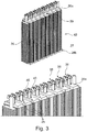
- FIG. 3 shows a heating block 42 with parallel electrical heating elements 36.
- the same items are denoted by the same reference numerals as in FIG. 1 and FIG. 2 ,
- Sealing elements 26 are arranged on the heating element 36 in each case in the marked with the rectangles bottom portion 27 and cover portion 29.
- the sealing element 26 in the lid region 29 is denoted here by the reference numeral 26a, and the sealing element in the bottom region 27 is designated by the reference numeral 26b.
- the reference numeral 26b In the lower section of FIG. 3 is shown in detail the arrangement of the heating elements 36 in the sealing elements 26a.
- Each heating element 36 protrudes with a connection element 40 through an opening 25 of the sealing element 26.
- FIG. 4 shows the electric heater 10 as a plan view of the housing cover 20.
- the same items are denoted by the same reference numerals as in the FIGS. 1 . 2 and 3 ,
- the sealing element 26, 26 a has on both sealing element sides 30 and 32 in each case two chamfers 28 a, 28 b and 28 c, 28 d. In each of the openings 24, a respective sealing element 26, 26 a is received.
- the housing cover 20 also has the chamfer 34 in the region of the opening 24.
- the chamfer 34 is arranged in each case at four positions of each opening 24, so that each bevel 28, 28a, 28b, 28c, 28d of the sealing element 26 has a chamfer 34, 34a, 34b, 34c, 34d of the housing cover 20 and / or housing bottom 22 arranged opposite one another ,
- the chamfer 28 and the chamfer 34 are designed such that they produce a positive connection and the sealing element 26, 26a is arranged in a form-fitting manner in the opening 24 of the housing cover 20.
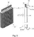
- FIG. 5 shows in the right half of the figure, the heating element 36 with an aluminum housing 38, which is designed as a flat aluminum tube 38 and in which not shown PTC heating elements are arranged on the inside.
- the aluminum housing 38 is not at potential.
- Each heating element 36 has the connection 40, by means of which the heating element 36 can be connected to an electrical supply.
- Several heating elements 36 are arranged in parallel in the electric heater 10 and form the heating block 42, which is shown in the left half of the figure.
- dirt and / or particles and / or dust and / or water can penetrate into the aluminum housing 38 through an open area 45 and damage the PTC heating elements 36.
- the open area 45 a is arranged in the lid area 29 and the open area 45 b is arranged in the floor area 27.
- FIG. 6 shows the heating block 42 of FIG. 5 , Like parts are designated by the same reference numerals.
- the heating block 42 is shown without sealing element 26, in the middle part of FIG. 4 the heating block 42 is shown in each case with the sealing element 26, 26a, 26b.
- the respective sealing element 26, 26a, 26b closes the respective open area 45, 45a, 45b of the aluminum housing 38.
- the connection 40 projects through the sealing element 26a in each case.
- the housing cover 20 with arranged in the openings 24 sealing elements 26, 26a but without heating elements 36 shown schematically as a plan view.
- the sealing element 26, 26 a has the opening 25 for receiving the heating element 36.
- the chamfers 28, 28a, 28b, 28c and / or 28d on the sealing element 26 and / or the chamfers 34, 34a, 34b, 34c and / or 34d are arranged on the housing cover 20.
- FIG. 7 shows the upper part of the heating block 42 and two housing half shells 48 and 50 of the housing 12.
- the electric heater 10 is shown in an exploded view, in which the heating block 42 and the housing half shells 48 and 50 can be seen as individual components.
- the electric heater 10 is assembled together and it is only the housing 12 to recognize as a whole.
- a plan view of the housing cover 20 is shown.
- a heating element 36 is arranged, wherein the heating element 36 is received in each case by a sealing element 26, 26 a, which at least partially closes the opening 24 so that no dirt and / or water can penetrate into the aluminum housing 38.
- the individual sealing elements 26, 26 a are joined together and executed as a one-piece seal, wherein each of the sealing elements 26 is connected to a web 52.
- a one-piece sealing element 54 is realized which consists of sealing elements 26, 26aa, 26ab, 26ac, 26an and webs 52, 52a, 52b, 52c, 52n-1.
- n designates the number of heating elements 36 and the number of openings 24.
- the assembly of the electric heating device 10 is very easy to realize by arranging the heating block 42, the sealing element 54 and the housing half-shells 48 and 50 with respect to each other and then assembling them together.
- FIG. 8 shows the complete heating block 42 and two housing half shells 48 and 50 of the housing 12.
- the same items are denoted by the same reference numerals and it is to the description FIG. 7 directed.
- sealing elements 26, 26b are arranged.
- the sealing elements 26b may be formed as individual sealing elements 26b or as an integral sealing element (not shown).
- one-piece sealing element 54 is shown from sealing elements 26a.
- the sealing element 54 is arranged with the sealing elements 26 a respectively in openings 24 of the housing cover 20.
- the arrows 53 show the sealing regions 53 realized by the respective chamfers 34 on the housing cover 20 and the chamfers 28 on the sealing element 26, 26 a, 54.
- the chamfers 34 and 28 allow accurate positioning and mounting of the heating elements 36 and the sealing elements 26, 26 a, 54 in the housing cover 20.
- the housing bottom 22 may also have not shown chamfers, which cooperate with not shown chamfers on the sealing element 26 b and a sealing area on Form housing bottom 22.
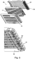
- FIG. 9 shows an electric heater 56, which differs from in the FIGS. 1 to 8 shown embodiment differs by a modified housing 58.
- the same items are denoted by the same reference numerals and the description of the FIGS. 1 to 8 directed.
- Differently designed articles belonging to the housing 58 are designated by other reference numerals.
- the housing 58 has two housing half-shells 60 and 62, which are also joined together, wherein the heating block 42 is arranged between the housing half-shells 60 and 62.
- a liquid silicone rubber 66 is injected at a position indicated by the arrows 68 as a sealing element in a housing cover 64 respectively.
- This silicone rubber 66 may form an unillustrated molded silicone rubber sealing member 66 in the assembled state.
- a silicone adhesive and / or a silicone gel can also be used. Openings in the open area 45, 45a, 45b of the respective heating element 36 can be closed in this way.
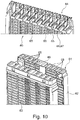
- FIG. 10 shows in the upper part of the housing half shell 60 with the silicone rubber 66, which is integrally formed as a silicone gasket 67, which forms the sealing member 67.
- the sealing member 67 is formed as a band of silicone rubber 66 and therefore can exactly conform to the shape of a respective opening 65 on the housing cover 64.
- the lower part of FIG. 10 shows the housing half shell 60 and the housing half shell 62 with a sealing element 69, wherein the sealing element 69 is formed from molded or formed silicone rubber 66 on the housing cover 64.
- the housing cover 64 can be overmolded with liquid silicone rubber 66, the silicone rubber 66 can harden and form the sealing element 69.
- the housing cover 64 is preferably designed as a one-piece component with the sealing element 69.
- the housing cover 64 can also be provided with the sealing element 69 made of silicone already during manufacture.
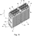
- FIG. 11 shows a further embodiment of an electric heater 70 in a perspective view.
- the electric heater 70 has a housing 72.
- the housing 72 has two housing half shells 74 and 76.
- Each of the housing halves 74 and 76 has a housing side member 78, housing front parts 80, a housing cover 82 and a housing bottom 84.
- the heating elements 88 preferably have PTC heating elements 88 (Positive Temperature Coefficient).
- the heating elements 88 are preferably arranged in an extension direction 90 of the electric heating device 70, indicated by the arrow 90, substantially parallel to one another in a row and form a heating block (not shown).
- the heating elements 88 may be arranged in a row or in two adjacent rows.
- FIG. 12 shows an enlarged view of the electric heater 70 with unclosed openings 86. Like parts are designated by the same reference numerals, as in FIG. 11 ,
- FIG. 13 shows the heater 70, wherein the heating elements 88 are each received in a sealing element 92.
- the sealing element 92 is designed as a molded seal or as an adhesive-spring combination.
- the sealing element 92 is in this case arranged directly on the housing cover 82 and / or the housing bottom 84, not shown. As a result, a tight connection between the heating element 88 and the housing cover 82 in the region of the openings 86 is realized. This can prevent the ingress of dust and / or dirt and water.
- the sealing member 92 may be made of a liquid silicone rubber. Alternatively, the sealing member 92 may be a silicone adhesive and / or silicone gel.
- the sealing element 92 is a flexible seal and is mounted directly on the housing 72, in particular on the housing cover 82 in the region of the openings 86.
- FIG. 14 shows in perspective a detailed view of the electric heater 70 (top view) and the heating elements 88 (bottom view).
- the heating elements 88 are designed as PTC radiator 88 and arranged in two juxtaposed rows.
- the heating elements 88 each have a connection 89, by means of which the heating elements 88 can be connected to a power supply, not shown.
- the housing 72 is preferably made of a plastic and the heating elements 88 are received in openings 86 and arranged. At the designated by arrows 91 areas of the housing 72 no silicone is arranged.
- FIG. 15 shows a perspective view of the electric heater 70 of FIG. 14 , Same objects are denoted by the same reference numerals designated.
- the housing is encapsulated with silicone.
- the sealing element 92 is formed by encapsulation with silicone.
- the housing 72 is encapsulated with silicone both in the cover area and in the floor area.
- the upper portion of the plastic frame of the housing 72 is shown spaced apart from the housing half shells 74 and 76 with the seal member 92.
- the housing 72 can be additionally encapsulated with silicone.
Landscapes
- Engineering & Computer Science (AREA)
- Physics & Mathematics (AREA)
- Thermal Sciences (AREA)
- Mechanical Engineering (AREA)
- Chemical & Material Sciences (AREA)
- Combustion & Propulsion (AREA)
- General Engineering & Computer Science (AREA)
- Air-Conditioning For Vehicles (AREA)
Claims (8)
- Dispositif de chauffage électrique comprenant des éléments chauffants (36, 88) qui sont disposés dans un boîtier (12, 56, 72), où le boîtier (12, 56, 72) présente un couvercle de boîtier (20, 82), un fond de boîtier (22, 84), un cadre en matière plastique (14), deux éléments latéraux (16) du boîtier et deux éléments frontaux (18) du boîtier, où il est prévu, dans le fond du boîtier et dans le couvercle du boîtier, des ouvertures (24, 86) dans lesquelles est disposé à chaque fois un élément chauffant (36, 88) comprenant un élément d'étanchéité, où il est prévu, dans l'ouverture respective (24, 86), un élément d'étanchéité (26, 54, 67, 69, 92) dans lequel est disposé l'élément chauffant respectif (36, 88), où le boîtier (12, 56, 72) présente deux demi-coques de boîtier (48, 50 ; 60, 62), où les demi-coques (48, 50 ; 60, 62) du boîtier sont disposées en étant pratiquement perpendiculaires au couvercle (20, 82) du boîtier et perpendiculaires au fond (22, 84) du boîtier.
- Dispositif de chauffage électrique selon la revendication 1, caractérisé en ce qu'il est prévu, sur le couvercle (20, 82) du boîtier et / ou sur le fond du boîtier, un chanfrein (34, 34a, 34b, 34c, 34d) formé sur une circonférence intérieure située dans la zone de l'ouverture (24, 86) du couvercle (20, 82) du boîtier et / ou du fond (22, 84) du boîtier.
- Dispositif de chauffage électrique selon l'une des revendications précédentes, caractérisé en ce qu'il est prévu un chanfrein (28, 28a, 28b, 28c, 28d) formé sur la circonférence de l'élément d'étanchéité, où le chanfrein (28, 28a, 28b, 28c, 28d) de l'élément d'étanchéité (26) et le chanfrein (34, 34a, 34b, 34c, 34d) du couvercle (20) du boîtier et / ou du fond du boîtier agissent de façon conjointe.
- Dispositif de chauffage électrique selon l'une quelconque des revendications précédentes, caractérisé en ce que le boîtier (20, 56, 72) est un boîtier en matière plastique, où au moins les demi-coques (48, 50 ; 60, 62) du boîtier sont fabriquées en matière plastique.
- Dispositif de chauffage électrique selon l'une quelconque des revendications précédentes, caractérisé en ce que le boîtier (20, 56, 72) est un boîtier en matière plastique.
- Dispositif de chauffage électrique selon l'une quelconque des revendications précédentes, caractérisé en ce que les éléments chauffants (36, 88) sont à chaque fois un élément chauffant à coefficient de température positif - CTP - ou bien un élément chauffant CTP pour véhicule hybride (HV).
- Dispositif de chauffage électrique selon l'une quelconque des revendications précédentes, caractérisé en ce que les éléments chauffants (36, 88) ou les éléments chauffants CTP forment un bloc chauffant (42).
- Véhicule automobile comprenant un dispositif de chauffage électrique (10, 70) selon l'une quelconque des revendications 1 à 7.
Priority Applications (2)
| Application Number | Priority Date | Filing Date | Title |
|---|---|---|---|
| EP14173063.0A EP2957840B1 (fr) | 2014-06-18 | 2014-06-18 | Dispositif de chauffage électrique |
| US14/742,767 US9894715B2 (en) | 2014-06-18 | 2015-06-18 | Electric heating device |
Applications Claiming Priority (1)
| Application Number | Priority Date | Filing Date | Title |
|---|---|---|---|
| EP14173063.0A EP2957840B1 (fr) | 2014-06-18 | 2014-06-18 | Dispositif de chauffage électrique |
Publications (2)
| Publication Number | Publication Date |
|---|---|
| EP2957840A1 EP2957840A1 (fr) | 2015-12-23 |
| EP2957840B1 true EP2957840B1 (fr) | 2019-10-02 |
Family
ID=50979573
Family Applications (1)
| Application Number | Title | Priority Date | Filing Date |
|---|---|---|---|
| EP14173063.0A Active EP2957840B1 (fr) | 2014-06-18 | 2014-06-18 | Dispositif de chauffage électrique |
Country Status (2)
| Country | Link |
|---|---|
| US (1) | US9894715B2 (fr) |
| EP (1) | EP2957840B1 (fr) |
Families Citing this family (4)
| Publication number | Priority date | Publication date | Assignee | Title |
|---|---|---|---|---|
| FR3075326B1 (fr) * | 2017-12-19 | 2020-05-15 | Valeo Systemes Thermiques | Dispositif de chauffage pour boitier de climatisation, notamment de vehicule automobile, et boitier de climatisation equipe d'un tel dispositif de chauffage |
| US11760056B2 (en) | 2018-12-05 | 2023-09-19 | Battelle Memorial Institute | Flexible foam resistive heaters and methods of making flexible resistive heaters |
| CN114643831B (zh) * | 2022-04-08 | 2024-02-13 | 安徽省宁国市天成电气有限公司 | 一种新能源汽车加热器 |
| FR3136140A1 (fr) * | 2022-05-24 | 2023-12-01 | Valeo Systemes Thermiques | Radiateur électrique avec joint de rétention surmoulé |
Citations (1)
| Publication number | Priority date | Publication date | Assignee | Title |
|---|---|---|---|---|
| DE102013103433A1 (de) * | 2012-04-13 | 2013-10-17 | Dbk David + Baader Gmbh | Elektrischer Zuheizer |
Family Cites Families (6)
| Publication number | Priority date | Publication date | Assignee | Title |
|---|---|---|---|---|
| US1992787A (en) * | 1932-08-05 | 1935-02-26 | Edison General Elec Appliance | Electric heater |
| DE502006003627D1 (de) | 2006-10-25 | 2009-06-10 | Catem Gmbh & Co Kg | Wärmeerzeugendes Element für eine elektrische Heizvorrichtung und Verfahren zur Herstellung derselben |
| ES2349351T3 (es) * | 2007-07-20 | 2010-12-30 | EBERSPÄCHER CATEM GMBH & CO. KG | Dispositivo eléctrico de calefacción en especial para vehículos a motor. |
| KR20090098029A (ko) | 2008-03-13 | 2009-09-17 | 센젠 산유안 일렉트로닉 캄퍼니 리미티드 | 밀폐형 정온도계수 서미스터 가열기 |
| EP2428747B2 (fr) * | 2010-09-13 | 2024-10-30 | MAHLE Behr GmbH & Co. KG | Echangeu de chaleur |
| EP2607121B2 (fr) * | 2011-12-22 | 2020-07-08 | Eberspächer catem GmbH & Co. KG | Dispositif de chauffage électrique, en particulier pour un véhicule automobile |
-
2014
- 2014-06-18 EP EP14173063.0A patent/EP2957840B1/fr active Active
-
2015
- 2015-06-18 US US14/742,767 patent/US9894715B2/en not_active Expired - Fee Related
Patent Citations (1)
| Publication number | Priority date | Publication date | Assignee | Title |
|---|---|---|---|---|
| DE102013103433A1 (de) * | 2012-04-13 | 2013-10-17 | Dbk David + Baader Gmbh | Elektrischer Zuheizer |
Also Published As
| Publication number | Publication date |
|---|---|
| US20150373784A1 (en) | 2015-12-24 |
| US9894715B2 (en) | 2018-02-13 |
| EP2957840A1 (fr) | 2015-12-23 |
Similar Documents
| Publication | Publication Date | Title |
|---|---|---|
| EP2017548B1 (fr) | Dispositif de chauffage électrique, en particulier pour véhicules automobiles | |
| EP3079442B1 (fr) | Dispositif de chauffage électrique et cadre associé | |
| EP1768457B1 (fr) | Element chauffant d'un dispositif de chauffage | |
| EP1916874B1 (fr) | Elément d'un dispositif de chauffage produisant de la chaleur | |
| EP3334243B1 (fr) | Dispositif de chauffage électrique | |
| EP3493650B1 (fr) | Dispositif de chauffage électrique | |
| EP2607121B2 (fr) | Dispositif de chauffage électrique, en particulier pour un véhicule automobile | |
| EP1768459B1 (fr) | Elément chauffant d'un dispositif de chauffage | |
| EP2873296B1 (fr) | Élément chauffant | |
| DE4133879A1 (de) | Elektrohydraulisches aggregat zur druckregelung in bremsanlagen von fahrzeugen | |
| EP2608631A1 (fr) | Elément générateur de chaleur | |
| DE102019205848A1 (de) | PTC-Heizelement und elektrische Heizvorrichtung mit einem solchen PTC-Heizelement und Verfahren zur Herstellung eines PTC-Heizelementes | |
| EP2608633A1 (fr) | Elément générateur de chaleur | |
| EP2607808A1 (fr) | Elément générateur de chaleur | |
| EP2884817A1 (fr) | Dispositif de chauffage électrique et son procédé de fabrication | |
| EP2884198B1 (fr) | Dispositif de chauffage électrique | |
| DE102012203634A1 (de) | Steuergerät zur Verwendung in einem Kraftfahrzeug | |
| EP4173072B1 (fr) | Élément de connexion pour éléments de batterie, module de connexion pour éléments de batterie, ensemble de connexion pour éléments de batterie et procédé pour tempérer et mettre en contact électrique des éléments de batterie | |
| DE202010018115U1 (de) | Steckerelement mit Verriegelungsabdichtung | |
| EP2884197B1 (fr) | Dispositif de chauffage électrique et son procédé de fabrication | |
| EP2884199B1 (fr) | Dispositif de chauffage électrique | |
| EP2957840A1 (fr) | Dispositif de chauffage électrique | |
| DE102013103433A1 (de) | Elektrischer Zuheizer | |
| DE102013000628A1 (de) | Halterahmen einer Frischluftklappe eines Kraftfahrzeuges sowie Frischluftklappe mit Halterahmen | |
| DE102019204472A1 (de) | Wärmeerzeugendes Element und elektrische Heizvorrichtung enthaltend ein solches |
Legal Events
| Date | Code | Title | Description |
|---|---|---|---|
| PUAI | Public reference made under article 153(3) epc to a published international application that has entered the european phase |
Free format text: ORIGINAL CODE: 0009012 |
|
| AK | Designated contracting states |
Kind code of ref document: A1 Designated state(s): AL AT BE BG CH CY CZ DE DK EE ES FI FR GB GR HR HU IE IS IT LI LT LU LV MC MK MT NL NO PL PT RO RS SE SI SK SM TR |
|
| AX | Request for extension of the european patent |
Extension state: BA ME |
|
| 17P | Request for examination filed |
Effective date: 20160623 |
|
| RBV | Designated contracting states (corrected) |
Designated state(s): AL AT BE BG CH CY CZ DE DK EE ES FI FR GB GR HR HU IE IS IT LI LT LU LV MC MK MT NL NO PL PT RO RS SE SI SK SM TR |
|
| STAA | Information on the status of an ep patent application or granted ep patent |
Free format text: STATUS: EXAMINATION IS IN PROGRESS |
|
| 17Q | First examination report despatched |
Effective date: 20170710 |
|
| RIC1 | Information provided on ipc code assigned before grant |
Ipc: F24H 3/04 20060101AFI20190405BHEP Ipc: F24H 9/18 20060101ALI20190405BHEP Ipc: B60H 1/22 20060101ALI20190405BHEP |
|
| GRAP | Despatch of communication of intention to grant a patent |
Free format text: ORIGINAL CODE: EPIDOSNIGR1 |
|
| STAA | Information on the status of an ep patent application or granted ep patent |
Free format text: STATUS: GRANT OF PATENT IS INTENDED |
|
| INTG | Intention to grant announced |
Effective date: 20190517 |
|
| GRAS | Grant fee paid |
Free format text: ORIGINAL CODE: EPIDOSNIGR3 |
|
| GRAJ | Information related to disapproval of communication of intention to grant by the applicant or resumption of examination proceedings by the epo deleted |
Free format text: ORIGINAL CODE: EPIDOSDIGR1 |
|
| GRAL | Information related to payment of fee for publishing/printing deleted |
Free format text: ORIGINAL CODE: EPIDOSDIGR3 |
|
| STAA | Information on the status of an ep patent application or granted ep patent |
Free format text: STATUS: EXAMINATION IS IN PROGRESS |
|
| GRAR | Information related to intention to grant a patent recorded |
Free format text: ORIGINAL CODE: EPIDOSNIGR71 |
|
| STAA | Information on the status of an ep patent application or granted ep patent |
Free format text: STATUS: GRANT OF PATENT IS INTENDED |
|
| GRAA | (expected) grant |
Free format text: ORIGINAL CODE: 0009210 |
|
| STAA | Information on the status of an ep patent application or granted ep patent |
Free format text: STATUS: THE PATENT HAS BEEN GRANTED |
|
| INTC | Intention to grant announced (deleted) | ||
| RIN1 | Information on inventor provided before grant (corrected) |
Inventor name: ZIRGEL, THOMAS |
|
| AK | Designated contracting states |
Kind code of ref document: B1 Designated state(s): AL AT BE BG CH CY CZ DE DK EE ES FI FR GB GR HR HU IE IS IT LI LT LU LV MC MK MT NL NO PL PT RO RS SE SI SK SM TR |
|
| INTG | Intention to grant announced |
Effective date: 20190823 |
|
| REG | Reference to a national code |
Ref country code: GB Ref legal event code: FG4D Free format text: NOT ENGLISH |
|
| REG | Reference to a national code |
Ref country code: CH Ref legal event code: EP Ref country code: AT Ref legal event code: REF Ref document number: 1186618 Country of ref document: AT Kind code of ref document: T Effective date: 20191015 |
|
| REG | Reference to a national code |
Ref country code: DE Ref legal event code: R096 Ref document number: 502014012744 Country of ref document: DE |
|
| REG | Reference to a national code |
Ref country code: IE Ref legal event code: FG4D Free format text: LANGUAGE OF EP DOCUMENT: GERMAN |
|
| REG | Reference to a national code |
Ref country code: NL Ref legal event code: MP Effective date: 20191002 |
|
| REG | Reference to a national code |
Ref country code: LT Ref legal event code: MG4D |
|
| PG25 | Lapsed in a contracting state [announced via postgrant information from national office to epo] |
Ref country code: PT Free format text: LAPSE BECAUSE OF FAILURE TO SUBMIT A TRANSLATION OF THE DESCRIPTION OR TO PAY THE FEE WITHIN THE PRESCRIBED TIME-LIMIT Effective date: 20200203 Ref country code: FI Free format text: LAPSE BECAUSE OF FAILURE TO SUBMIT A TRANSLATION OF THE DESCRIPTION OR TO PAY THE FEE WITHIN THE PRESCRIBED TIME-LIMIT Effective date: 20191002 Ref country code: NO Free format text: LAPSE BECAUSE OF FAILURE TO SUBMIT A TRANSLATION OF THE DESCRIPTION OR TO PAY THE FEE WITHIN THE PRESCRIBED TIME-LIMIT Effective date: 20200102 Ref country code: BG Free format text: LAPSE BECAUSE OF FAILURE TO SUBMIT A TRANSLATION OF THE DESCRIPTION OR TO PAY THE FEE WITHIN THE PRESCRIBED TIME-LIMIT Effective date: 20200102 Ref country code: SE Free format text: LAPSE BECAUSE OF FAILURE TO SUBMIT A TRANSLATION OF THE DESCRIPTION OR TO PAY THE FEE WITHIN THE PRESCRIBED TIME-LIMIT Effective date: 20191002 Ref country code: LV Free format text: LAPSE BECAUSE OF FAILURE TO SUBMIT A TRANSLATION OF THE DESCRIPTION OR TO PAY THE FEE WITHIN THE PRESCRIBED TIME-LIMIT Effective date: 20191002 Ref country code: NL Free format text: LAPSE BECAUSE OF FAILURE TO SUBMIT A TRANSLATION OF THE DESCRIPTION OR TO PAY THE FEE WITHIN THE PRESCRIBED TIME-LIMIT Effective date: 20191002 Ref country code: LT Free format text: LAPSE BECAUSE OF FAILURE TO SUBMIT A TRANSLATION OF THE DESCRIPTION OR TO PAY THE FEE WITHIN THE PRESCRIBED TIME-LIMIT Effective date: 20191002 Ref country code: GR Free format text: LAPSE BECAUSE OF FAILURE TO SUBMIT A TRANSLATION OF THE DESCRIPTION OR TO PAY THE FEE WITHIN THE PRESCRIBED TIME-LIMIT Effective date: 20200103 Ref country code: PL Free format text: LAPSE BECAUSE OF FAILURE TO SUBMIT A TRANSLATION OF THE DESCRIPTION OR TO PAY THE FEE WITHIN THE PRESCRIBED TIME-LIMIT Effective date: 20191002 Ref country code: ES Free format text: LAPSE BECAUSE OF FAILURE TO SUBMIT A TRANSLATION OF THE DESCRIPTION OR TO PAY THE FEE WITHIN THE PRESCRIBED TIME-LIMIT Effective date: 20191002 |
|
| PG25 | Lapsed in a contracting state [announced via postgrant information from national office to epo] |
Ref country code: CZ Free format text: LAPSE BECAUSE OF FAILURE TO SUBMIT A TRANSLATION OF THE DESCRIPTION OR TO PAY THE FEE WITHIN THE PRESCRIBED TIME-LIMIT Effective date: 20191002 Ref country code: IS Free format text: LAPSE BECAUSE OF FAILURE TO SUBMIT A TRANSLATION OF THE DESCRIPTION OR TO PAY THE FEE WITHIN THE PRESCRIBED TIME-LIMIT Effective date: 20200224 Ref country code: HR Free format text: LAPSE BECAUSE OF FAILURE TO SUBMIT A TRANSLATION OF THE DESCRIPTION OR TO PAY THE FEE WITHIN THE PRESCRIBED TIME-LIMIT Effective date: 20191002 Ref country code: RS Free format text: LAPSE BECAUSE OF FAILURE TO SUBMIT A TRANSLATION OF THE DESCRIPTION OR TO PAY THE FEE WITHIN THE PRESCRIBED TIME-LIMIT Effective date: 20191002 |
|
| PG25 | Lapsed in a contracting state [announced via postgrant information from national office to epo] |
Ref country code: AL Free format text: LAPSE BECAUSE OF FAILURE TO SUBMIT A TRANSLATION OF THE DESCRIPTION OR TO PAY THE FEE WITHIN THE PRESCRIBED TIME-LIMIT Effective date: 20191002 |
|
| REG | Reference to a national code |
Ref country code: DE Ref legal event code: R097 Ref document number: 502014012744 Country of ref document: DE |
|
| PG2D | Information on lapse in contracting state deleted |
Ref country code: IS |
|
| PG25 | Lapsed in a contracting state [announced via postgrant information from national office to epo] |
Ref country code: DK Free format text: LAPSE BECAUSE OF FAILURE TO SUBMIT A TRANSLATION OF THE DESCRIPTION OR TO PAY THE FEE WITHIN THE PRESCRIBED TIME-LIMIT Effective date: 20191002 Ref country code: RO Free format text: LAPSE BECAUSE OF FAILURE TO SUBMIT A TRANSLATION OF THE DESCRIPTION OR TO PAY THE FEE WITHIN THE PRESCRIBED TIME-LIMIT Effective date: 20191002 Ref country code: EE Free format text: LAPSE BECAUSE OF FAILURE TO SUBMIT A TRANSLATION OF THE DESCRIPTION OR TO PAY THE FEE WITHIN THE PRESCRIBED TIME-LIMIT Effective date: 20191002 Ref country code: IS Free format text: LAPSE BECAUSE OF FAILURE TO SUBMIT A TRANSLATION OF THE DESCRIPTION OR TO PAY THE FEE WITHIN THE PRESCRIBED TIME-LIMIT Effective date: 20200202 |
|
| PLBE | No opposition filed within time limit |
Free format text: ORIGINAL CODE: 0009261 |
|
| STAA | Information on the status of an ep patent application or granted ep patent |
Free format text: STATUS: NO OPPOSITION FILED WITHIN TIME LIMIT |
|
| PG25 | Lapsed in a contracting state [announced via postgrant information from national office to epo] |
Ref country code: SM Free format text: LAPSE BECAUSE OF FAILURE TO SUBMIT A TRANSLATION OF THE DESCRIPTION OR TO PAY THE FEE WITHIN THE PRESCRIBED TIME-LIMIT Effective date: 20191002 Ref country code: IT Free format text: LAPSE BECAUSE OF FAILURE TO SUBMIT A TRANSLATION OF THE DESCRIPTION OR TO PAY THE FEE WITHIN THE PRESCRIBED TIME-LIMIT Effective date: 20191002 Ref country code: SK Free format text: LAPSE BECAUSE OF FAILURE TO SUBMIT A TRANSLATION OF THE DESCRIPTION OR TO PAY THE FEE WITHIN THE PRESCRIBED TIME-LIMIT Effective date: 20191002 |
|
| 26N | No opposition filed |
Effective date: 20200703 |
|
| PG25 | Lapsed in a contracting state [announced via postgrant information from national office to epo] |
Ref country code: SI Free format text: LAPSE BECAUSE OF FAILURE TO SUBMIT A TRANSLATION OF THE DESCRIPTION OR TO PAY THE FEE WITHIN THE PRESCRIBED TIME-LIMIT Effective date: 20191002 |
|
| PG25 | Lapsed in a contracting state [announced via postgrant information from national office to epo] |
Ref country code: MC Free format text: LAPSE BECAUSE OF FAILURE TO SUBMIT A TRANSLATION OF THE DESCRIPTION OR TO PAY THE FEE WITHIN THE PRESCRIBED TIME-LIMIT Effective date: 20191002 |
|
| REG | Reference to a national code |
Ref country code: CH Ref legal event code: PL |
|
| GBPC | Gb: european patent ceased through non-payment of renewal fee |
Effective date: 20200618 |
|
| PG25 | Lapsed in a contracting state [announced via postgrant information from national office to epo] |
Ref country code: LU Free format text: LAPSE BECAUSE OF NON-PAYMENT OF DUE FEES Effective date: 20200618 |
|
| REG | Reference to a national code |
Ref country code: BE Ref legal event code: MM Effective date: 20200630 |
|
| PG25 | Lapsed in a contracting state [announced via postgrant information from national office to epo] |
Ref country code: LI Free format text: LAPSE BECAUSE OF NON-PAYMENT OF DUE FEES Effective date: 20200630 Ref country code: GB Free format text: LAPSE BECAUSE OF NON-PAYMENT OF DUE FEES Effective date: 20200618 Ref country code: IE Free format text: LAPSE BECAUSE OF NON-PAYMENT OF DUE FEES Effective date: 20200618 Ref country code: CH Free format text: LAPSE BECAUSE OF NON-PAYMENT OF DUE FEES Effective date: 20200630 Ref country code: FR Free format text: LAPSE BECAUSE OF NON-PAYMENT OF DUE FEES Effective date: 20200630 |
|
| PG25 | Lapsed in a contracting state [announced via postgrant information from national office to epo] |
Ref country code: BE Free format text: LAPSE BECAUSE OF NON-PAYMENT OF DUE FEES Effective date: 20200630 |
|
| REG | Reference to a national code |
Ref country code: AT Ref legal event code: MM01 Ref document number: 1186618 Country of ref document: AT Kind code of ref document: T Effective date: 20200618 |
|
| PG25 | Lapsed in a contracting state [announced via postgrant information from national office to epo] |
Ref country code: AT Free format text: LAPSE BECAUSE OF NON-PAYMENT OF DUE FEES Effective date: 20200618 |
|
| PG25 | Lapsed in a contracting state [announced via postgrant information from national office to epo] |
Ref country code: TR Free format text: LAPSE BECAUSE OF FAILURE TO SUBMIT A TRANSLATION OF THE DESCRIPTION OR TO PAY THE FEE WITHIN THE PRESCRIBED TIME-LIMIT Effective date: 20191002 Ref country code: MT Free format text: LAPSE BECAUSE OF FAILURE TO SUBMIT A TRANSLATION OF THE DESCRIPTION OR TO PAY THE FEE WITHIN THE PRESCRIBED TIME-LIMIT Effective date: 20191002 Ref country code: CY Free format text: LAPSE BECAUSE OF FAILURE TO SUBMIT A TRANSLATION OF THE DESCRIPTION OR TO PAY THE FEE WITHIN THE PRESCRIBED TIME-LIMIT Effective date: 20191002 |
|
| PG25 | Lapsed in a contracting state [announced via postgrant information from national office to epo] |
Ref country code: MK Free format text: LAPSE BECAUSE OF FAILURE TO SUBMIT A TRANSLATION OF THE DESCRIPTION OR TO PAY THE FEE WITHIN THE PRESCRIBED TIME-LIMIT Effective date: 20191002 |
|
| P01 | Opt-out of the competence of the unified patent court (upc) registered |
Effective date: 20240527 |
|
| PGFP | Annual fee paid to national office [announced via postgrant information from national office to epo] |
Ref country code: DE Payment date: 20240619 Year of fee payment: 11 |
|
| REG | Reference to a national code |
Ref country code: DE Ref legal event code: R119 Ref document number: 502014012744 Country of ref document: DE |
|
| PG25 | Lapsed in a contracting state [announced via postgrant information from national office to epo] |
Ref country code: DE Free format text: LAPSE BECAUSE OF NON-PAYMENT OF DUE FEES Effective date: 20260101 |