EP2017638B1 - Système et procédé d'estimation de l'emplacement d'un dispositif local et dispositif local - Google Patents
Système et procédé d'estimation de l'emplacement d'un dispositif local et dispositif local Download PDFInfo
- Publication number
- EP2017638B1 EP2017638B1 EP07024655.8A EP07024655A EP2017638B1 EP 2017638 B1 EP2017638 B1 EP 2017638B1 EP 07024655 A EP07024655 A EP 07024655A EP 2017638 B1 EP2017638 B1 EP 2017638B1
- Authority
- EP
- European Patent Office
- Prior art keywords
- time
- local device
- signal
- location
- flight
- Prior art date
- Legal status (The legal status is an assumption and is not a legal conclusion. Google has not performed a legal analysis and makes no representation as to the accuracy of the status listed.)
- Not-in-force
Links
- 238000000034 method Methods 0.000 title claims description 10
- 238000001514 detection method Methods 0.000 description 7
- 238000005259 measurement Methods 0.000 description 6
- 238000010586 diagram Methods 0.000 description 5
- 238000012795 verification Methods 0.000 description 5
- 238000013459 approach Methods 0.000 description 3
- 238000002592 echocardiography Methods 0.000 description 3
- 238000012545 processing Methods 0.000 description 3
- 230000004913 activation Effects 0.000 description 2
- 230000001360 synchronised effect Effects 0.000 description 2
- 238000007476 Maximum Likelihood Methods 0.000 description 1
- 239000006096 absorbing agent Substances 0.000 description 1
- 230000003044 adaptive effect Effects 0.000 description 1
- 238000013528 artificial neural network Methods 0.000 description 1
- 238000007689 inspection Methods 0.000 description 1
- 230000000704 physical effect Effects 0.000 description 1
- 238000012549 training Methods 0.000 description 1
- 230000001960 triggered effect Effects 0.000 description 1
- 238000010200 validation analysis Methods 0.000 description 1
Images


Classifications
-
- G—PHYSICS
- G01—MEASURING; TESTING
- G01S—RADIO DIRECTION-FINDING; RADIO NAVIGATION; DETERMINING DISTANCE OR VELOCITY BY USE OF RADIO WAVES; LOCATING OR PRESENCE-DETECTING BY USE OF THE REFLECTION OR RERADIATION OF RADIO WAVES; ANALOGOUS ARRANGEMENTS USING OTHER WAVES
- G01S5/00—Position-fixing by co-ordinating two or more direction or position line determinations; Position-fixing by co-ordinating two or more distance determinations
- G01S5/02—Position-fixing by co-ordinating two or more direction or position line determinations; Position-fixing by co-ordinating two or more distance determinations using radio waves
- G01S5/0252—Radio frequency fingerprinting
- G01S5/02521—Radio frequency fingerprinting using a radio-map
-
- G—PHYSICS
- G01—MEASURING; TESTING
- G01S—RADIO DIRECTION-FINDING; RADIO NAVIGATION; DETERMINING DISTANCE OR VELOCITY BY USE OF RADIO WAVES; LOCATING OR PRESENCE-DETECTING BY USE OF THE REFLECTION OR RERADIATION OF RADIO WAVES; ANALOGOUS ARRANGEMENTS USING OTHER WAVES
- G01S5/00—Position-fixing by co-ordinating two or more direction or position line determinations; Position-fixing by co-ordinating two or more distance determinations
- G01S5/02—Position-fixing by co-ordinating two or more direction or position line determinations; Position-fixing by co-ordinating two or more distance determinations using radio waves
- G01S5/10—Position of receiver fixed by co-ordinating a plurality of position lines defined by path-difference measurements, e.g. omega or decca systems
Definitions
- the present invention relates to a method for estimating a location of a local device and a related system for estimating a location of a local device and the local device.
- Outdoor location systems are ubiquitous, e.g. in navigation systems of cars, phones and even watches.
- One of these location systems is the global navigation satellite system. This system is based on a time of arrival approach.
- the satellites have precisely synchronized clocks.
- Each satellite regularly broadcasts a signal stamped with a global time.
- the signals are arriving at the local device at different local times due to the differently long distances from the satellites to the local device.
- the local device determines based on the time differences the relative distances to the satellites and by means of trilateration its actual location.
- An aproach to provide an indoor geolocation system is given in " Algorithm for TOA-based indoor geolocation" published by M. Kanaan and K. Pahlavan in Electronics Letters, vol. 40, no. 22, October 28, 2004 .
- the geolocation system is based on a time of arrival approach.
- the expected time of arrival from certain points is known.
- the system determines an estimated location based on a search for a minimal difference of a measured time of arrival and the expected time of arrival from the certain points.
- the present invention provides an alternative approach for an indoor geolocation system and a method for estimating a location of a local device which may avoid the use of synchronized clocks.
- a method for estimating a location of a local device comprises the following steps:
- a system for estimating a location of a local device comprises:
- a local device for performing a method according to the first aspect comprises:
- a set up of the first embodiment is demonstrated for an exemplary surrounding.
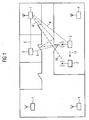
- a floor plan of an apartment having several rooms and respective doors is illustrated in figure 1 .
- a plurality of beacons 1 is arranged in some or all of the rooms. Two or more beacons 1 may be arranged in one room, in particular in larger rooms.
- the beacons 1 are stationary at well defined positions.
- a person moving in the apartment carries a local device 2.
- the local device 2 and the beacons 1 do interact such that a location of the local device 2 may be determined or estimated and provided to the person.
- the estimation of the location of the local device 2 is based on time of flight measurements.
- the time of flight value depends on the shortest distance of the local device 2 to the selected beacon 1.
- the relation of the time of flight value and the shortest distance is determined by the travelling speed of the signal.
- a signal is dampened by absorbers, like walls, doors, non-metallic objects etc, placed along a travelling path.
- the signal along the shortest distance 4 is dampened by two walls in the exemplary situation of figure 1 .
- the signal along the alternative travelling path 6 is dampened by another wall and maybe damped by two doors which can be opened or closed individually.
- a signal travelling through two walls or two doors is assumed to be just damped below a detection limit of receiving units in the local device 2 and the beacon 1, respectively.
- a signal travelling along the shortest path 4 is not detected.
- a time of flight measurement performed by the beacon 1 and the local device 2 does not reflect the shortest path 4.
- both doors may be open along the alternative travelling path 6.
- the signal strength remains above the detection limit.
- a time of flight measurement performed may reflect the longer distance according to the alternative travelling path 6 as no measurement corresponding to the shortest distance 4 could be obtained.
- one of the doors may be closed.
- the signal strength of the signal along the alternative path 6 is dropped below the detection limit, too.
- a signal travelling along a second alternative path 6' may now provide the only signal above the detection limit.
- a different time of flight value is obtained just by closing one door and without a change of the location of the local device 2.
- a movement of the local device 2 along a direction 17 may provide a discontinuous increase or decrease of time of flight values.
- the local device 2 may be moved to a further location 2' where no obstacle is in the line of sight 18 between the local device 2 and the beacon 1.
- the signal travelling along an alternative travelling path 6' provides a sufficient signal strength.
- the signal strength of a signal travelling along the shortest distance 18 rises above the detection limit.
- the time of flight values measured drop from a larger time of flight value corresponding to the alternative travelling path 6' down to a lower time of flight value corresponding to the shortest distance 18. This discontinuity of the time of flight values measured reflects the discontinuity caused by the detection limit of sensors used.
- a first embodiment of a method for estimating the location of the local device may deal with above situations.
- a brief description of a local device 2 and a beacon 1 according to a first embodiment is given which may be used for a method to estimate the location of the local device 2.
- the local device 2 comprises a timer 3, a trigger generator 4, an emitter 5, a receiver 6, a threshold sensor 7, and an estimation means 8.
- the trigger generator 4 generates a trigger signal 10 which is synchronously forwarded to the timer 3 and the emitter 5.
- the timer 3 is reset and started by the trigger signal 10.
- the emitter 5 broadcasts the trigger signal 10.
- the trigger signal 10 may be encoded such that it addresses a single specified beacon 1.
- the trigger signal 10 may be encoded by a unique sequence of pulses or by a unique carrier frequency, for instance.
- the receiver 6 receives a signal 11 broadcasted by the beacon 1.
- the signal 11 is forwarded to the threshold sensor 7.
- the threshold sensor 7 outputs a stop signal 12 at the moment the incoming signal 11 rises above a threshold value.
- the stop signal 12 is forwarded to the timer 3 such that the timer 3 is stopped.
- the timer 3 transmits the measured duration, i.e. the value of the time interval between the trigger signal 10 and the stop signal 12, to an estimation means 8.
- Each beacon 1 may encode a unique signature into the signal. Therefore, a signal decoder 13 and a verification device 14 may be provided in the local device 2.
- the incoming signal 11 is provided to the signal decoder 13.
- the signal decoder 13 decodes the incoming signal 11 and determines the beacon 1 which broadcasted the incoming signal 11.
- the verification device 14 verifies that the incoming signal 11 corresponds to the same beacon 1 which has previously been addressed by the trigger signal 10. If so the verification device 14 confirms the measured duration with an approval signal 15 sent to the estimation means 8.
- the signal decoder 13 may be activated by the stop signal 12.
- the beacon 1 comprises a receiver 20, a threshold detector 21, a trigger decoder 22, a signal generator 23, and an emitter 24 ( figure 3 ).
- the receiver 20 may receive an incoming trigger signal 25 which has been previously emitted by the local device 2.
- the optional threshold detector 21 outputs an activation signal 26 when the incoming trigger signal 25 exceeds a threshold value.
- the trigger decoder 22 may be activated by the activation signal 26.
- the trigger decoder 22 decodes the incoming trigger signal 25 and determines whether the beacon 1 is addressed by the incoming trigger signal 25. If so the signal generator 23 is activated for generating a signal 27.
- the signal 27 may be provided with a signature which is unique for each of the beacons 1 used.
- the signal 27 is broadcasted by the emitter 24.
- the first embodiment of a method for estimating the location is explained along with a flow diagram in figure 4 .
- the local device 2 generates a trigger signal 10 by means of its trigger generator 4.
- the timer 3 is started.
- the trigger signal 10 is encoded to address a specific one of the beacons 1 and emitted by the emitter 5 (step 101).
- the trigger signal 10 travels along a plurality of travelling paths 4, 6 to the beacons 1. Each of the beacons 1 receives a trigger signal 25 being part of the emitted trigger signal 10.
- the trigger signal 10 may be damped, distorted, provided with several echoes, etc.
- the beacon 1 addressed by the trigger signal 25 returns a signal 27 upon receipt of the trigger signal 10 (step 102). There may be a delay of processing the trigger signal 10 and generating the signal 27 by means of the signal generator 23.
- the signal 27 travels along a plurality of travelling paths 4, 6 to the local device 2.
- the local device 2 receives an incoming signal 11 being part of the emitted signal 27.
- the incoming signal 11 may be damped, distorted, provided with several echoes, etc.
- the threshold sensor 7 stops the timer 3 when the signal strength of the incoming signal 11 rises above a predetermined threshold value (step 103).
- the duration measured by the timer 3 is forwarded to the estimation means 8 (step 104).
- the estimation means 8 stores the duration and interprets the duration as a time of flight value of the signal 27 between the local device 2 and the beacon 1 addressed by the trigger signal 10.
- time of flight values are gathered for the same beacon 1 by repeating steps 101 to 104 several times (loop 105).
- An average value for the several time of flight values is obtained using a Gaussian filter (step 110).
- a histogram of the time of flight values may be determined and a Gaussian distribution is fitted to the histogram.
- the mean value of the Gaussian distribution may be taken as average of the time of flight values.
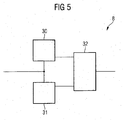
- the average value is stored in a first memory 30 of the estimation means 8 ( figure 5 ).
- beacons 1 are addressed in sequence by means of differently encoded trigger signals 10 (loop 111). An average time of flight value is obtained for each of the other beacons 1 and stored in the first memory 30 as outlined above along with steps 101 to 110. Some beacons 1 may not respond because the trigger signal 10 or the signal 27 is dampened below detection limits of the receivers 6, 25. Preferably, the sequence is repeated until at least average time of flight values corresponding to three different beacons 1 could be obtained.
- a map of the area in which the local device 2 may move is stored in a second memory 31 of the estimation means 8.
- the map contains a reference set, so-called fingerprints, for some reference locations in the area.
- Each fingerprint comprises a set of time of flight values the local device 10 would determine at the reference location.
- the fingerprints may be obtained during a training by moving the local device 10 to the reference locations and determining average time of flight values as outlined above taking reference to steps 101 to 110.
- the average time of flight values are stored in the second memory 31.
- Movable objects in the area may be moved into different positions.
- the movable objects may affect the time of flight values.
- an embodiment provides additional fingerprints for at least some of the locations for which the movable objects are arranged in different positions.
- the additional fingerprints are stored in the second memory 31.
- the map may contain several fingerprints for a single location.
- the map may contain additional to the location information additional information referring to the position of movable objects in the area.
- the movable objects may be doors, movable walls, furniture, vehicles, robots, parts of machines etc.
- the estimation means 8 estimates the location of the local device 2 using a predictor means 32.
- the predictor means 32 loads the set of reference values, i.e. the map of fingerprints, and applies a prediction algorithm to the reference set and the actual average flight of time values stored in the first memory 31.
- the prediction algorithms may use neural networks, adaptive filters, or a maximum likelihood estimation.
- An underlying concept of some of the prediction algorithms is to determine the difference of the actual value and each reference value and to sum up the reference locations weighted by the difference. The estimated location is taken for the weighted sum.
- the trigger signal 10 may be not encoded, but addresses all beacons 1 simultaneously.
- the threshold sensor 7 emits a release signal 12 when the incoming signal 11 caused by a beacon 1 rises above the threshold value.
- the timer 3 forwards the duration between the trigger signal and the release signal 12 to the estimation means 8 but the timer 3 is not reset or stopped. Thus, the timer 3 may forward the duration value between the trigger signal and a further release signal 12 caused by a further beacon 1.
- the signal decoder 13 decodes a signature of the emitting beacon 1 in the incoming signal 11.
- the verification device 14 may confirm based on the signature that the incoming signal 11 is of beacon selected of a specified group of beacons 1.
- the verification device 14 forwards a signal 15 to the estimation means 8.
- the signal 15 may be encoded with a canceling information such that the estimation means 8 clears a previously obtained duration value from the first memory 31.
- the signal 15 may be encoded to forward the signature of the beacon 1 such that the estimation means 8 can store the signature of the beacon 1 along with the previously obtained duration value.
- the timer 3 is not triggered by the threshold sensor 7 but by the validation means 14.
- the duration measured by the timer 3 thus includes the processing time of the decoder 13.
- the map of fingerprints should be obtained by the same local device 2 or an equally configured device which will be used in the area. Therefore, the map may account for the processing time of the decoder 13.
- standard WLAN transmitter devices may be used for the local device 2 and the beacons 1.
- the WLAN transmitter device can be reconfigured to provide the timer 3, the trigger generator 4, the emitter 5, the receiver 6, and the threshold sensor 7.
- Equally a WLAN transmitter device can be reconfigured to provide the receiver 20, the threshold detector 21, the trigger decoder 22, the signal generator 23, and the emitter 24.
- Other standard devices like RFID-transmitters, UMTS-transmitters, GSM-transmitters, WiMaX-transmitters, UWB-transmitters, bluetooth-transmitters may be reconfigured to be used in a local device 2 and a beacon 1.
- the estimation means 8 may be arranged in one of the beacons 1 or a separate device instead being placed on the local device 2.
- the duration measured by the timer 3, i.e. the time of flight values can be broadcasted to the estimation means via the emitter 5 or a separate emitter.
- the estimation means 8 estimates the location of the local device 2 and forward the estimated location via a broadcast signal to the local device 2.
- the local device 2 may be provided with a display for indicating the estimated location.
- the beacons 1 comprise a timer 3, a trigger generator 4, an emitter 5, a receiver 6, and a threshold sensor 7.
- the local device 2 comprises a receiver 20, a threshold detector 21, a trigger decoder 22, a signal generator 23, and an emitter 24.
- the beacons 1 emit the trigger signal 10 and the local device 2 returns a signal 27 upon receipt of the trigger signal 10.
- the time of flight values measured by the beacons 1 are forwarded to an estimation means 8.
- the estimation means 8 performs a location estimation as outlined along with the above embodiments.
Landscapes
- Physics & Mathematics (AREA)
- Engineering & Computer Science (AREA)
- General Physics & Mathematics (AREA)
- Radar, Positioning & Navigation (AREA)
- Remote Sensing (AREA)
- Position Fixing By Use Of Radio Waves (AREA)
Claims (6)
- Un procédé d'estimation d'un emplacement d'un dispositif local, comprenant les étapes suivantes :la radiodiffusion d'un signal entre au moins une balise (1) et un dispositif local au niveau d'un emplacement,la détermination d'une valeur de temps de vol pour le signal radiodiffusé par la au moins une balise (1) de façon à obtenir un ensemble réel de valeurs de temps de vol,caractérisé parl'estimation de l'emplacement d'un dispositif local (2) par l'application d'un algorithme à l'ensemble réel de valeurs de temps de vol et à au moins un ensemble de référence de valeurs de temps de vol,chaque ensemble de référence de valeurs de temps de vol correspondant à un emplacement connu du dispositif local (2),dans lequel le au moins un ensemble de référence de valeurs de temps de vol est obtenu par le placement du dispositif local (2) à un emplacement connu, la détermination du au moins un ensemble de référence de valeurs de temps de vol et la conservation en mémoire du au moins un ensemble de référence de valeurs de temps de vol en tant qu'ensemble de référence de valeurs de temps de vol pour l'emplacement connu,dans lequel ledit algorithme est capable de déterminer une différence entre la valeur réelle de temps de vol et chaque valeur de référence dudit au moins un ensemble de référence de valeurs de temps de vol et d'additionner des emplacements de référence pondérés par la différence, etdans lequel l'emplacement estimé est la somme pondérée.
- Le procédé selon la revendication 1, dans lequel la valeur de temps de vol est déterminée comme étant un intervalle temporel débutant au moment où un signal déclencheur qui est émis par le dispositif local (2) ou par l'une des balises (1) met en route une horloge et se terminant au moment où le dispositif local (2) ou la balise (1) détecte une première élévation au-dessus d'une valeur seuil de l'intensité d'un signal renvoyé par la balise (1) ou le dispositif local (2) respectivement après réception du signal déclencheur.
- Un système d'estimation d'un emplacement d'un dispositif local (2), comprenant :au moins une balise (1), chacune d'elles émettant un signal en fonction d'un signal déclencheur (10),un dispositif local (2) possédant un générateur de déclencheurs (4) destiné à l'émission du signal déclencheur (10),un capteur de seuil (7) destiné à la détection d'une première élévation du signal, émis par l'une des au moins une balises (1), au-dessus d'un seuil, et une horloge (3) raccordée au générateur de déclencheurs (4) et au capteur de seuil (7) pour la détermination d'une valeur de temps de vol entre une des balises (1) de ladite au moins une balise (1) et le dispositif local (2) au niveau d'un emplacement,un dispositif à mémoire (31) conservant en mémoire au moins un ensemble de référence de valeurs de temps de vol, chaque ensemble de référence correspondant à un emplacement connu du dispositif local (2),dans lequel le au moins un ensemble de référence est obtenu par le placement du dispositif local (2) à un emplacement connu, la détermination du au moins un ensemble de référence de valeurs de temps de vol, et la conservation en mémoire des valeurs de temps de vol en tant qu'ensemble de référence de valeurs de temps de vol pour l'emplacement connu dans le dispositif à mémoire (31), etun moyen d'estimation (8) pour l'estimation de l'emplacement du dispositif local (2) par l'application d'un algorithme à l'ensemble réel de valeurs de temps de vol pour le dispositif local (2) au niveau de l'emplacement et au au moins un ensemble de référence de valeurs de temps de vol,dans lequel ledit algorithme est capable de déterminer une différence entre la valeur réelle de temps de vol et chaque valeur de référence dudit au moins un ensemble de référence de valeurs de temps de vol et d'additionner des emplacements de référence pondérés par la différence, etdans lequel l'emplacement estimé est la somme pondérée.
- Le système selon la revendication 3, le dispositif local (2) comprenant un émetteur radio pour la transmission de l'ensemble réel de valeurs de temps de vol au moyen d'estimation (8) et un récepteur destiné à la réception de l'emplacement estimé.
- Le système selon la revendication 3 ou 4, dans lequel la balise (1) est au moins un émetteur parmi un émetteur WLAN, un émetteur RFID, un émetteur GSM, un émetteur UMTS et un émetteur WiMaX.
- Le système selon la revendication 5, dans lequel ledit générateur de déclencheurs (4) est compris par ladite au moins une balise (1).
Priority Applications (2)
| Application Number | Priority Date | Filing Date | Title |
|---|---|---|---|
| EP07024655.8A EP2017638B1 (fr) | 2007-07-17 | 2007-12-19 | Système et procédé d'estimation de l'emplacement d'un dispositif local et dispositif local |
| PCT/EP2008/058609 WO2009010401A2 (fr) | 2007-07-17 | 2008-07-03 | Système et procédé pour estimer une localisation d'un dispositif local et dispositif local |
Applications Claiming Priority (2)
| Application Number | Priority Date | Filing Date | Title |
|---|---|---|---|
| EP07013996 | 2007-07-17 | ||
| EP07024655.8A EP2017638B1 (fr) | 2007-07-17 | 2007-12-19 | Système et procédé d'estimation de l'emplacement d'un dispositif local et dispositif local |
Publications (3)
| Publication Number | Publication Date |
|---|---|
| EP2017638A2 EP2017638A2 (fr) | 2009-01-21 |
| EP2017638A3 EP2017638A3 (fr) | 2009-03-18 |
| EP2017638B1 true EP2017638B1 (fr) | 2014-07-16 |
Family
ID=39884602
Family Applications (1)
| Application Number | Title | Priority Date | Filing Date |
|---|---|---|---|
| EP07024655.8A Not-in-force EP2017638B1 (fr) | 2007-07-17 | 2007-12-19 | Système et procédé d'estimation de l'emplacement d'un dispositif local et dispositif local |
Country Status (2)
| Country | Link |
|---|---|
| EP (1) | EP2017638B1 (fr) |
| WO (1) | WO2009010401A2 (fr) |
Families Citing this family (7)
| Publication number | Priority date | Publication date | Assignee | Title |
|---|---|---|---|---|
| US8022877B2 (en) | 2009-07-16 | 2011-09-20 | Skyhook Wireless, Inc. | Systems and methods for using a satellite positioning system to detect moved WLAN access points |
| CN103119470B (zh) * | 2010-07-21 | 2015-09-16 | 韩国贸易信息通信株式会社 | 进行室内导航的基于位置服务的系统和方法 |
| US20140077998A1 (en) * | 2012-09-17 | 2014-03-20 | Yuval Amizur | Supplemental location-related information transmit in unassociated wireless states |
| US10466337B2 (en) | 2013-12-10 | 2019-11-05 | Intel IP Corporation | Techniques for wireless time-of-flight calculation complexity reduction |
| US9629064B2 (en) | 2015-03-20 | 2017-04-18 | Bkon Connect, Inc. | Beacon-implemented system for mobile content management |
| US9571985B2 (en) * | 2015-04-09 | 2017-02-14 | Datalogic Ip Tech S.R.L. | High accuracy indoor locating system |
| US10375060B1 (en) | 2016-02-10 | 2019-08-06 | Bkon Connect, Inc. | System for mobile content and metadata management |
Family Cites Families (4)
| Publication number | Priority date | Publication date | Assignee | Title |
|---|---|---|---|---|
| US4533871A (en) * | 1981-08-10 | 1985-08-06 | Dsl Dynamic Sciences Limited | Range-enable information system for plural mobile objects |
| US6522296B2 (en) * | 2001-06-25 | 2003-02-18 | Harris Corporation | Method and system for calibrating wireless location systems |
| US20040085242A1 (en) * | 2002-10-30 | 2004-05-06 | Nicole Brousseau | Synthetic Doppler system and method for locating cooperative transceivers |
| WO2007067821A2 (fr) * | 2005-12-09 | 2007-06-14 | The Regents Of The University Of California | Radios a bande ultralarge de mesure du temps de vol et d'estimation de la position de reseaux |
-
2007
- 2007-12-19 EP EP07024655.8A patent/EP2017638B1/fr not_active Not-in-force
-
2008
- 2008-07-03 WO PCT/EP2008/058609 patent/WO2009010401A2/fr not_active Ceased
Also Published As
| Publication number | Publication date |
|---|---|
| WO2009010401A3 (fr) | 2009-04-09 |
| EP2017638A3 (fr) | 2009-03-18 |
| WO2009010401A2 (fr) | 2009-01-22 |
| EP2017638A2 (fr) | 2009-01-21 |
Similar Documents
| Publication | Publication Date | Title |
|---|---|---|
| EP2017638A2 (fr) | Système et procédé d'estimation de l'emplacement d'un dispositif local et dispositif local | |
| CA3069208C (fr) | Systeme et methode de notification de mouvement imminent pour barriere mobile | |
| US8400353B2 (en) | Apparatus and method for use in global position measurements | |
| AU760936B2 (en) | Improvements in and relating to position estimation systems | |
| JP4957770B2 (ja) | 位置推定システム、位置推定装置、位置推定方法及びプログラム | |
| KR101417737B1 (ko) | 센서를 구비한 실내 측위 시스템 및 그 위치 확인 방법 | |
| US20140062793A1 (en) | Methods and devices for channel identification | |
| US20090102707A1 (en) | Systems and methods for transparency mapping using multipath signals | |
| EP3078222A1 (fr) | Procédé et système d'estimation de la position d'un dispositif récepteur | |
| US20190158982A1 (en) | Radio-location method for locating a target device contained within a region of space | |
| CN103609137A (zh) | 背景物体传感器 | |
| KR101150259B1 (ko) | 다중분리 레이더에서의 이동 표적 위치 추적 방법 및 장치와 이동 표적 위치 추적 방법을 실행하기 위한 프로그램이 기록된 기록매체 | |
| WO1996042020A2 (fr) | Calcul de position ameliore | |
| US9860005B2 (en) | Method for operating mobile platforms | |
| CN107422358A (zh) | 一种全场景定位方法及系统 | |
| EP4109123A1 (fr) | Système et procédé pour faciliter la localisation d'un objet externe | |
| WO2014070174A1 (fr) | Procédés d'examen acoustique dans des systèmes de localisation d'armes | |
| KR101591164B1 (ko) | Uwb 레이더의 객체 검출 방법 및 장치 | |
| US9743252B2 (en) | System and method for locating devices in predetermined premises | |
| US10794987B2 (en) | Hybrid IR-US RTLS system | |
| KR100752580B1 (ko) | 위치 추정 방법 | |
| KR101917503B1 (ko) | 직교 코드가 포함된 수중음향신호를 이용한 다중 수중표적 거리 추정 방법 및 시스템 | |
| KR20230084247A (ko) | 차량의 측면 환경 측정 방법, 측정 장치 및 차량 | |
| Hammoud et al. | Enhanced still presence sensing with supervised learning over segmented ultrasonic reflections | |
| US20220317274A1 (en) | Method and system for detecting an object |
Legal Events
| Date | Code | Title | Description |
|---|---|---|---|
| PUAI | Public reference made under article 153(3) epc to a published international application that has entered the european phase |
Free format text: ORIGINAL CODE: 0009012 |
|
| AK | Designated contracting states |
Kind code of ref document: A2 Designated state(s): AT BE BG CH CY CZ DE DK EE ES FI FR GB GR HU IE IS IT LI LT LU LV MC MT NL PL PT RO SE SI SK TR |
|
| AX | Request for extension of the european patent |
Extension state: AL BA HR MK RS |
|
| PUAL | Search report despatched |
Free format text: ORIGINAL CODE: 0009013 |
|
| AK | Designated contracting states |
Kind code of ref document: A3 Designated state(s): AT BE BG CH CY CZ DE DK EE ES FI FR GB GR HU IE IS IT LI LT LU LV MC MT NL PL PT RO SE SI SK TR |
|
| AX | Request for extension of the european patent |
Extension state: AL BA HR MK RS |
|
| 17P | Request for examination filed |
Effective date: 20090916 |
|
| 17Q | First examination report despatched |
Effective date: 20091020 |
|
| AKX | Designation fees paid |
Designated state(s): AT BE BG CH CY CZ DE DK EE ES FI FR GB GR HU IE IS IT LI LT LU LV MC MT NL PL PT RO SE SI SK TR |
|
| RAP1 | Party data changed (applicant data changed or rights of an application transferred) |
Owner name: SIEMENS AKTIENGESELLSCHAFT |
|
| RIC1 | Information provided on ipc code assigned before grant |
Ipc: G01S 5/02 20100101AFI20131204BHEP Ipc: G01S 5/10 20060101ALI20131204BHEP |
|
| GRAP | Despatch of communication of intention to grant a patent |
Free format text: ORIGINAL CODE: EPIDOSNIGR1 |
|
| INTG | Intention to grant announced |
Effective date: 20140204 |
|
| GRAS | Grant fee paid |
Free format text: ORIGINAL CODE: EPIDOSNIGR3 |
|
| GRAA | (expected) grant |
Free format text: ORIGINAL CODE: 0009210 |
|
| AK | Designated contracting states |
Kind code of ref document: B1 Designated state(s): AT BE BG CH CY CZ DE DK EE ES FI FR GB GR HU IE IS IT LI LT LU LV MC MT NL PL PT RO SE SI SK TR |
|
| REG | Reference to a national code |
Ref country code: GB Ref legal event code: FG4D |
|
| REG | Reference to a national code |
Ref country code: CH Ref legal event code: EP |
|
| REG | Reference to a national code |
Ref country code: IE Ref legal event code: FG4D |
|
| REG | Reference to a national code |
Ref country code: AT Ref legal event code: REF Ref document number: 677956 Country of ref document: AT Kind code of ref document: T Effective date: 20140815 |
|
| REG | Reference to a national code |
Ref country code: DE Ref legal event code: R096 Ref document number: 602007037620 Country of ref document: DE Effective date: 20140821 |
|
| REG | Reference to a national code |
Ref country code: NL Ref legal event code: VDEP Effective date: 20140716 |
|
| REG | Reference to a national code |
Ref country code: AT Ref legal event code: MK05 Ref document number: 677956 Country of ref document: AT Kind code of ref document: T Effective date: 20140716 |
|
| REG | Reference to a national code |
Ref country code: LT Ref legal event code: MG4D |
|
| PG25 | Lapsed in a contracting state [announced via postgrant information from national office to epo] |
Ref country code: SE Free format text: LAPSE BECAUSE OF FAILURE TO SUBMIT A TRANSLATION OF THE DESCRIPTION OR TO PAY THE FEE WITHIN THE PRESCRIBED TIME-LIMIT Effective date: 20140716 Ref country code: FI Free format text: LAPSE BECAUSE OF FAILURE TO SUBMIT A TRANSLATION OF THE DESCRIPTION OR TO PAY THE FEE WITHIN THE PRESCRIBED TIME-LIMIT Effective date: 20140716 Ref country code: PT Free format text: LAPSE BECAUSE OF FAILURE TO SUBMIT A TRANSLATION OF THE DESCRIPTION OR TO PAY THE FEE WITHIN THE PRESCRIBED TIME-LIMIT Effective date: 20141117 Ref country code: ES Free format text: LAPSE BECAUSE OF FAILURE TO SUBMIT A TRANSLATION OF THE DESCRIPTION OR TO PAY THE FEE WITHIN THE PRESCRIBED TIME-LIMIT Effective date: 20140716 Ref country code: LT Free format text: LAPSE BECAUSE OF FAILURE TO SUBMIT A TRANSLATION OF THE DESCRIPTION OR TO PAY THE FEE WITHIN THE PRESCRIBED TIME-LIMIT Effective date: 20140716 Ref country code: GR Free format text: LAPSE BECAUSE OF FAILURE TO SUBMIT A TRANSLATION OF THE DESCRIPTION OR TO PAY THE FEE WITHIN THE PRESCRIBED TIME-LIMIT Effective date: 20141017 Ref country code: BG Free format text: LAPSE BECAUSE OF FAILURE TO SUBMIT A TRANSLATION OF THE DESCRIPTION OR TO PAY THE FEE WITHIN THE PRESCRIBED TIME-LIMIT Effective date: 20141016 |
|
| PG25 | Lapsed in a contracting state [announced via postgrant information from national office to epo] |
Ref country code: AT Free format text: LAPSE BECAUSE OF FAILURE TO SUBMIT A TRANSLATION OF THE DESCRIPTION OR TO PAY THE FEE WITHIN THE PRESCRIBED TIME-LIMIT Effective date: 20140716 Ref country code: LV Free format text: LAPSE BECAUSE OF FAILURE TO SUBMIT A TRANSLATION OF THE DESCRIPTION OR TO PAY THE FEE WITHIN THE PRESCRIBED TIME-LIMIT Effective date: 20140716 Ref country code: CY Free format text: LAPSE BECAUSE OF FAILURE TO SUBMIT A TRANSLATION OF THE DESCRIPTION OR TO PAY THE FEE WITHIN THE PRESCRIBED TIME-LIMIT Effective date: 20140716 Ref country code: NL Free format text: LAPSE BECAUSE OF FAILURE TO SUBMIT A TRANSLATION OF THE DESCRIPTION OR TO PAY THE FEE WITHIN THE PRESCRIBED TIME-LIMIT Effective date: 20140716 Ref country code: PL Free format text: LAPSE BECAUSE OF FAILURE TO SUBMIT A TRANSLATION OF THE DESCRIPTION OR TO PAY THE FEE WITHIN THE PRESCRIBED TIME-LIMIT Effective date: 20140716 Ref country code: IS Free format text: LAPSE BECAUSE OF FAILURE TO SUBMIT A TRANSLATION OF THE DESCRIPTION OR TO PAY THE FEE WITHIN THE PRESCRIBED TIME-LIMIT Effective date: 20141116 |
|
| REG | Reference to a national code |
Ref country code: DE Ref legal event code: R097 Ref document number: 602007037620 Country of ref document: DE |
|
| PG25 | Lapsed in a contracting state [announced via postgrant information from national office to epo] |
Ref country code: RO Free format text: LAPSE BECAUSE OF FAILURE TO SUBMIT A TRANSLATION OF THE DESCRIPTION OR TO PAY THE FEE WITHIN THE PRESCRIBED TIME-LIMIT Effective date: 20140716 Ref country code: IT Free format text: LAPSE BECAUSE OF FAILURE TO SUBMIT A TRANSLATION OF THE DESCRIPTION OR TO PAY THE FEE WITHIN THE PRESCRIBED TIME-LIMIT Effective date: 20140716 Ref country code: DK Free format text: LAPSE BECAUSE OF FAILURE TO SUBMIT A TRANSLATION OF THE DESCRIPTION OR TO PAY THE FEE WITHIN THE PRESCRIBED TIME-LIMIT Effective date: 20140716 Ref country code: SK Free format text: LAPSE BECAUSE OF FAILURE TO SUBMIT A TRANSLATION OF THE DESCRIPTION OR TO PAY THE FEE WITHIN THE PRESCRIBED TIME-LIMIT Effective date: 20140716 Ref country code: CZ Free format text: LAPSE BECAUSE OF FAILURE TO SUBMIT A TRANSLATION OF THE DESCRIPTION OR TO PAY THE FEE WITHIN THE PRESCRIBED TIME-LIMIT Effective date: 20140716 Ref country code: EE Free format text: LAPSE BECAUSE OF FAILURE TO SUBMIT A TRANSLATION OF THE DESCRIPTION OR TO PAY THE FEE WITHIN THE PRESCRIBED TIME-LIMIT Effective date: 20140716 |
|
| PLBE | No opposition filed within time limit |
Free format text: ORIGINAL CODE: 0009261 |
|
| STAA | Information on the status of an ep patent application or granted ep patent |
Free format text: STATUS: NO OPPOSITION FILED WITHIN TIME LIMIT |
|
| 26N | No opposition filed |
Effective date: 20150417 |
|
| PG25 | Lapsed in a contracting state [announced via postgrant information from national office to epo] |
Ref country code: BE Free format text: LAPSE BECAUSE OF NON-PAYMENT OF DUE FEES Effective date: 20141231 |
|
| PG25 | Lapsed in a contracting state [announced via postgrant information from national office to epo] |
Ref country code: LU Free format text: LAPSE BECAUSE OF FAILURE TO SUBMIT A TRANSLATION OF THE DESCRIPTION OR TO PAY THE FEE WITHIN THE PRESCRIBED TIME-LIMIT Effective date: 20141219 |
|
| REG | Reference to a national code |
Ref country code: CH Ref legal event code: PL |
|
| REG | Reference to a national code |
Ref country code: IE Ref legal event code: MM4A |
|
| PG25 | Lapsed in a contracting state [announced via postgrant information from national office to epo] |
Ref country code: LI Free format text: LAPSE BECAUSE OF NON-PAYMENT OF DUE FEES Effective date: 20141231 Ref country code: IE Free format text: LAPSE BECAUSE OF NON-PAYMENT OF DUE FEES Effective date: 20141219 Ref country code: CH Free format text: LAPSE BECAUSE OF NON-PAYMENT OF DUE FEES Effective date: 20141231 |
|
| PG25 | Lapsed in a contracting state [announced via postgrant information from national office to epo] |
Ref country code: SI Free format text: LAPSE BECAUSE OF FAILURE TO SUBMIT A TRANSLATION OF THE DESCRIPTION OR TO PAY THE FEE WITHIN THE PRESCRIBED TIME-LIMIT Effective date: 20140716 |
|
| REG | Reference to a national code |
Ref country code: FR Ref legal event code: PLFP Year of fee payment: 9 |
|
| PGFP | Annual fee paid to national office [announced via postgrant information from national office to epo] |
Ref country code: GB Payment date: 20151209 Year of fee payment: 9 |
|
| PGFP | Annual fee paid to national office [announced via postgrant information from national office to epo] |
Ref country code: FR Payment date: 20151214 Year of fee payment: 9 |
|
| PGFP | Annual fee paid to national office [announced via postgrant information from national office to epo] |
Ref country code: DE Payment date: 20160219 Year of fee payment: 9 |
|
| PG25 | Lapsed in a contracting state [announced via postgrant information from national office to epo] |
Ref country code: MC Free format text: LAPSE BECAUSE OF FAILURE TO SUBMIT A TRANSLATION OF THE DESCRIPTION OR TO PAY THE FEE WITHIN THE PRESCRIBED TIME-LIMIT Effective date: 20140716 |
|
| PG25 | Lapsed in a contracting state [announced via postgrant information from national office to epo] |
Ref country code: TR Free format text: LAPSE BECAUSE OF FAILURE TO SUBMIT A TRANSLATION OF THE DESCRIPTION OR TO PAY THE FEE WITHIN THE PRESCRIBED TIME-LIMIT Effective date: 20140716 Ref country code: HU Free format text: LAPSE BECAUSE OF FAILURE TO SUBMIT A TRANSLATION OF THE DESCRIPTION OR TO PAY THE FEE WITHIN THE PRESCRIBED TIME-LIMIT; INVALID AB INITIO Effective date: 20071219 Ref country code: MT Free format text: LAPSE BECAUSE OF FAILURE TO SUBMIT A TRANSLATION OF THE DESCRIPTION OR TO PAY THE FEE WITHIN THE PRESCRIBED TIME-LIMIT Effective date: 20140716 Ref country code: BE Free format text: LAPSE BECAUSE OF FAILURE TO SUBMIT A TRANSLATION OF THE DESCRIPTION OR TO PAY THE FEE WITHIN THE PRESCRIBED TIME-LIMIT Effective date: 20140716 |
|
| REG | Reference to a national code |
Ref country code: DE Ref legal event code: R119 Ref document number: 602007037620 Country of ref document: DE |
|
| GBPC | Gb: european patent ceased through non-payment of renewal fee |
Effective date: 20161219 |
|
| REG | Reference to a national code |
Ref country code: FR Ref legal event code: ST Effective date: 20170831 |
|
| PG25 | Lapsed in a contracting state [announced via postgrant information from national office to epo] |
Ref country code: FR Free format text: LAPSE BECAUSE OF NON-PAYMENT OF DUE FEES Effective date: 20170102 |
|
| PG25 | Lapsed in a contracting state [announced via postgrant information from national office to epo] |
Ref country code: DE Free format text: LAPSE BECAUSE OF NON-PAYMENT OF DUE FEES Effective date: 20170701 Ref country code: GB Free format text: LAPSE BECAUSE OF NON-PAYMENT OF DUE FEES Effective date: 20161219 |