EP2017660A2 - Optische Faser, optisches Faserband und optisches Verbindungssystem - Google Patents
Optische Faser, optisches Faserband und optisches Verbindungssystem Download PDFInfo
- Publication number
- EP2017660A2 EP2017660A2 EP08167146A EP08167146A EP2017660A2 EP 2017660 A2 EP2017660 A2 EP 2017660A2 EP 08167146 A EP08167146 A EP 08167146A EP 08167146 A EP08167146 A EP 08167146A EP 2017660 A2 EP2017660 A2 EP 2017660A2
- Authority
- EP
- European Patent Office
- Prior art keywords
- core
- optical fiber
- optical
- fiber
- wavelength
- Prior art date
- Legal status (The legal status is an assumption and is not a legal conclusion. Google has not performed a legal analysis and makes no representation as to the accuracy of the status listed.)
- Ceased
Links
- 239000013307 optical fiber Substances 0.000 title claims abstract description 98
- 230000003287 optical effect Effects 0.000 title claims description 58
- 238000005452 bending Methods 0.000 claims abstract description 39
- 230000005540 biological transmission Effects 0.000 claims abstract description 34
- 238000005253 cladding Methods 0.000 claims abstract description 31
- VYPSYNLAJGMNEJ-UHFFFAOYSA-N Silicium dioxide Chemical compound O=[Si]=O VYPSYNLAJGMNEJ-UHFFFAOYSA-N 0.000 claims abstract description 16
- 239000011347 resin Substances 0.000 claims description 34
- 229920005989 resin Polymers 0.000 claims description 34
- RNFJDJUURJAICM-UHFFFAOYSA-N 2,2,4,4,6,6-hexaphenoxy-1,3,5-triaza-2$l^{5},4$l^{5},6$l^{5}-triphosphacyclohexa-1,3,5-triene Chemical compound N=1P(OC=2C=CC=CC=2)(OC=2C=CC=CC=2)=NP(OC=2C=CC=CC=2)(OC=2C=CC=CC=2)=NP=1(OC=1C=CC=CC=1)OC1=CC=CC=C1 RNFJDJUURJAICM-UHFFFAOYSA-N 0.000 claims description 25
- 239000003063 flame retardant Substances 0.000 claims description 25
- 239000011248 coating agent Substances 0.000 claims description 21
- 238000000576 coating method Methods 0.000 claims description 21
- 238000001723 curing Methods 0.000 claims description 16
- 238000001029 thermal curing Methods 0.000 claims description 4
- 239000000835 fiber Substances 0.000 description 74
- 238000004088 simulation Methods 0.000 description 10
- 230000000994 depressogenic effect Effects 0.000 description 7
- 238000013461 design Methods 0.000 description 6
- 230000014509 gene expression Effects 0.000 description 5
- 230000008054 signal transmission Effects 0.000 description 5
- 239000004925 Acrylic resin Substances 0.000 description 4
- 229910001218 Gallium arsenide Inorganic materials 0.000 description 4
- 229910000530 Gallium indium arsenide Inorganic materials 0.000 description 4
- 238000004891 communication Methods 0.000 description 4
- UHESRSKEBRADOO-UHFFFAOYSA-N ethyl carbamate;prop-2-enoic acid Chemical compound OC(=O)C=C.CCOC(N)=O UHESRSKEBRADOO-UHFFFAOYSA-N 0.000 description 4
- 238000007706 flame test Methods 0.000 description 4
- 229910052732 germanium Inorganic materials 0.000 description 4
- GNPVGFCGXDBREM-UHFFFAOYSA-N germanium atom Chemical compound [Ge] GNPVGFCGXDBREM-UHFFFAOYSA-N 0.000 description 4
- 239000000377 silicon dioxide Substances 0.000 description 4
- WKBOTKDWSSQWDR-UHFFFAOYSA-N Bromine atom Chemical compound [Br] WKBOTKDWSSQWDR-UHFFFAOYSA-N 0.000 description 3
- PXGOKWXKJXAPGV-UHFFFAOYSA-N Fluorine Chemical compound FF PXGOKWXKJXAPGV-UHFFFAOYSA-N 0.000 description 3
- 230000015572 biosynthetic process Effects 0.000 description 3
- GDTBXPJZTBHREO-UHFFFAOYSA-N bromine Substances BrBr GDTBXPJZTBHREO-UHFFFAOYSA-N 0.000 description 3
- 229910052794 bromium Inorganic materials 0.000 description 3
- 230000008878 coupling Effects 0.000 description 3
- 238000010168 coupling process Methods 0.000 description 3
- 238000005859 coupling reaction Methods 0.000 description 3
- 229910052731 fluorine Inorganic materials 0.000 description 3
- 239000011737 fluorine Substances 0.000 description 3
- 239000000463 material Substances 0.000 description 3
- -1 phosphorus compound Chemical class 0.000 description 3
- 238000003860 storage Methods 0.000 description 3
- ZAMOUSCENKQFHK-UHFFFAOYSA-N Chlorine atom Chemical compound [Cl] ZAMOUSCENKQFHK-UHFFFAOYSA-N 0.000 description 2
- ADCOVFLJGNWWNZ-UHFFFAOYSA-N antimony trioxide Chemical compound O=[Sb]O[Sb]=O ADCOVFLJGNWWNZ-UHFFFAOYSA-N 0.000 description 2
- 229910052801 chlorine Inorganic materials 0.000 description 2
- 239000000460 chlorine Substances 0.000 description 2
- 238000000354 decomposition reaction Methods 0.000 description 2
- 230000000694 effects Effects 0.000 description 2
- NLYAJNPCOHFWQQ-UHFFFAOYSA-N kaolin Chemical compound O.O.O=[Al]O[Si](=O)O[Si](=O)O[Al]=O NLYAJNPCOHFWQQ-UHFFFAOYSA-N 0.000 description 2
- 238000004519 manufacturing process Methods 0.000 description 2
- 230000004048 modification Effects 0.000 description 2
- 238000012986 modification Methods 0.000 description 2
- 229910052698 phosphorus Inorganic materials 0.000 description 2
- 239000011574 phosphorus Substances 0.000 description 2
- 229920002994 synthetic fiber Polymers 0.000 description 2
- 229920001169 thermoplastic Polymers 0.000 description 2
- 239000004416 thermosoftening plastic Substances 0.000 description 2
- 229910019142 PO4 Inorganic materials 0.000 description 1
- OAICVXFJPJFONN-UHFFFAOYSA-N Phosphorus Chemical compound [P] OAICVXFJPJFONN-UHFFFAOYSA-N 0.000 description 1
- TYLJDUHYONPOSB-UHFFFAOYSA-N [Sb]1C(c2ccccc2)C1(c1ccccc1)c1ccccc1 Chemical compound [Sb]1C(c2ccccc2)C1(c1ccccc1)c1ccccc1 TYLJDUHYONPOSB-UHFFFAOYSA-N 0.000 description 1
- NIXOWILDQLNWCW-UHFFFAOYSA-N acrylic acid group Chemical group C(C=C)(=O)O NIXOWILDQLNWCW-UHFFFAOYSA-N 0.000 description 1
- 239000000654 additive Substances 0.000 description 1
- 230000000996 additive effect Effects 0.000 description 1
- 230000002411 adverse Effects 0.000 description 1
- WNROFYMDJYEPJX-UHFFFAOYSA-K aluminium hydroxide Chemical compound [OH-].[OH-].[OH-].[Al+3] WNROFYMDJYEPJX-UHFFFAOYSA-K 0.000 description 1
- 229910021502 aluminium hydroxide Inorganic materials 0.000 description 1
- 150000001463 antimony compounds Chemical class 0.000 description 1
- 230000008859 change Effects 0.000 description 1
- 150000001875 compounds Chemical class 0.000 description 1
- 230000007423 decrease Effects 0.000 description 1
- 230000003247 decreasing effect Effects 0.000 description 1
- 239000006185 dispersion Substances 0.000 description 1
- 238000005516 engineering process Methods 0.000 description 1
- 229910052736 halogen Inorganic materials 0.000 description 1
- 230000026030 halogenation Effects 0.000 description 1
- 238000005658 halogenation reaction Methods 0.000 description 1
- 150000002367 halogens Chemical class 0.000 description 1
- 238000010438 heat treatment Methods 0.000 description 1
- VTHJTEIRLNZDEV-UHFFFAOYSA-L magnesium dihydroxide Chemical compound [OH-].[OH-].[Mg+2] VTHJTEIRLNZDEV-UHFFFAOYSA-L 0.000 description 1
- 239000000347 magnesium hydroxide Substances 0.000 description 1
- 229910001862 magnesium hydroxide Inorganic materials 0.000 description 1
- 238000000034 method Methods 0.000 description 1
- 239000000203 mixture Substances 0.000 description 1
- 239000000178 monomer Substances 0.000 description 1
- 239000010452 phosphate Substances 0.000 description 1
- 230000002265 prevention Effects 0.000 description 1
- 230000008569 process Effects 0.000 description 1
- 238000012216 screening Methods 0.000 description 1
- 230000035945 sensitivity Effects 0.000 description 1
- 238000012360 testing method Methods 0.000 description 1
Images


Classifications
-
- G—PHYSICS
- G02—OPTICS
- G02B—OPTICAL ELEMENTS, SYSTEMS OR APPARATUS
- G02B6/00—Light guides; Structural details of arrangements comprising light guides and other optical elements, e.g. couplings
- G02B6/02—Optical fibres with cladding with or without a coating
- G02B6/028—Optical fibres with cladding with or without a coating with core or cladding having graded refractive index
- G02B6/0281—Graded index region forming part of the central core segment, e.g. alpha profile, triangular, trapezoidal core
-
- G—PHYSICS
- G02—OPTICS
- G02B—OPTICAL ELEMENTS, SYSTEMS OR APPARATUS
- G02B6/00—Light guides; Structural details of arrangements comprising light guides and other optical elements, e.g. couplings
- G02B6/02—Optical fibres with cladding with or without a coating
- G02B6/036—Optical fibres with cladding with or without a coating core or cladding comprising multiple layers
- G02B6/03616—Optical fibres characterised both by the number of different refractive index layers around the central core segment, i.e. around the innermost high index core layer, and their relative refractive index difference
- G02B6/03622—Optical fibres characterised both by the number of different refractive index layers around the central core segment, i.e. around the innermost high index core layer, and their relative refractive index difference having 2 layers only
- G02B6/03627—Optical fibres characterised both by the number of different refractive index layers around the central core segment, i.e. around the innermost high index core layer, and their relative refractive index difference having 2 layers only arranged - +
-
- G—PHYSICS
- G02—OPTICS
- G02B—OPTICAL ELEMENTS, SYSTEMS OR APPARATUS
- G02B6/00—Light guides; Structural details of arrangements comprising light guides and other optical elements, e.g. couplings
- G02B6/02—Optical fibres with cladding with or without a coating
- G02B6/036—Optical fibres with cladding with or without a coating core or cladding comprising multiple layers
- G02B6/03616—Optical fibres characterised both by the number of different refractive index layers around the central core segment, i.e. around the innermost high index core layer, and their relative refractive index difference
- G02B6/03638—Optical fibres characterised both by the number of different refractive index layers around the central core segment, i.e. around the innermost high index core layer, and their relative refractive index difference having 3 layers only
- G02B6/03644—Optical fibres characterised both by the number of different refractive index layers around the central core segment, i.e. around the innermost high index core layer, and their relative refractive index difference having 3 layers only arranged - + -
-
- G—PHYSICS
- G02—OPTICS
- G02B—OPTICAL ELEMENTS, SYSTEMS OR APPARATUS
- G02B6/00—Light guides; Structural details of arrangements comprising light guides and other optical elements, e.g. couplings
- G02B6/02—Optical fibres with cladding with or without a coating
- G02B6/036—Optical fibres with cladding with or without a coating core or cladding comprising multiple layers
- G02B6/03616—Optical fibres characterised both by the number of different refractive index layers around the central core segment, i.e. around the innermost high index core layer, and their relative refractive index difference
- G02B6/03638—Optical fibres characterised both by the number of different refractive index layers around the central core segment, i.e. around the innermost high index core layer, and their relative refractive index difference having 3 layers only
- G02B6/0365—Optical fibres characterised both by the number of different refractive index layers around the central core segment, i.e. around the innermost high index core layer, and their relative refractive index difference having 3 layers only arranged - - +
-
- G—PHYSICS
- G02—OPTICS
- G02B—OPTICAL ELEMENTS, SYSTEMS OR APPARATUS
- G02B6/00—Light guides; Structural details of arrangements comprising light guides and other optical elements, e.g. couplings
- G02B6/44—Mechanical structures for providing tensile strength and external protection for fibres, e.g. optical transmission cables
- G02B6/4401—Optical cables
- G02B6/4429—Means specially adapted for strengthening or protecting the cables
- G02B6/4436—Heat resistant
-
- G—PHYSICS
- G02—OPTICS
- G02B—OPTICAL ELEMENTS, SYSTEMS OR APPARATUS
- G02B6/00—Light guides; Structural details of arrangements comprising light guides and other optical elements, e.g. couplings
- G02B6/02—Optical fibres with cladding with or without a coating
- G02B6/028—Optical fibres with cladding with or without a coating with core or cladding having graded refractive index
- G02B6/0288—Multimode fibre, e.g. graded index core for compensating modal dispersion
Definitions
- the present invention relates to an optical fiber, and, more particularly to an optical fiber and an optical fiber ribbon for optical wiring in equipment, ribbon and an optical interconnection system using the optical fiber or the optical fiber ribbon.
- the electrical transmission has a problem with electrical crosstalk due to high density wiring as well as recent high CPU clock speed, thereby requiring specific applications such as reshaping.
- the electrical transmission when used as a signal transmission in equipment, allows a transmission range of at most 100 meters and a transmission rate of at most 10 Gbps.
- the optical interconnection when used as a signal transmission in equipment, allows extreme broadband transmission as compared with the electrical transmission, and can provide a signal transmission system using optical elements with small size and low power consumption. Therefore, the optical interconnection system now draws attention as a signal transmission in equipment replacing the electrical transmission.
- the optical interconnection uses, for example, optical waveguide circuits or optical fibers, to transmit optical signals. Since it is preferable that all the optical elements used in equipment occupy as little space as possible, the optical fiber, which allows flexible wiring and low loss optical transmission, is especially an optical element suitable for the optical interconnection.
- MMFs multimode fibers
- a conventional MMF fiber has a core diameter about ten times that of a singlemode fiber (SMF), in other words, its numerical aperture is sufficiently large. Accordingly, the MMF fiber does not require an accurate connection between the fiber and other optical element such as a light source, thereby allowing an easy connection.
- a vertically cavity surface emitting laser (VCSEL) with an emission wavelength of 850 nanometers and a graded index optical fiber are widely used as a light source and an optical transmission medium, respectively.
- VCSEL vertically cavity surface emitting laser
- the graded index optical fiber which is a type of multimode fiber, has a core with an optimal formation of refractive index profile to mitigate the impact of mode dispersion.
- the graded index optical fiber in which the formation of refractive index profile is accurately controlled allows high-speed optical communication at about a transmission rate of 10 Gbps and over a range of about 100 meters.
- a GaInAs/GaAs laser diode As a light source used for such application, a GaInAs/GaAs laser diode is now being studied.
- This laser diode has an emission wavelength of 1100 to 1200 nanometers, a low lasing threshold, and excellent temperature characteristics, may be directly modulated at 10 Gbps, and is therefore drawing attention as a light source for local area network (LAN), for example. Since the emission wavelength can be controlled, so far one with an emission wavelength of 1100 nanometer and one with 1200 nanometers are being studying and are presented at an academic conference and the like.
- a transmission system through SMF fibers using GaInAs/GaAs quantum well lasers as a light source is disclosed in Gain F. Koyama et al., 1.2 ⁇ m highly strained GaInAs/GaAs quantum well lasers for single-mode fibre datalink, ELECTRONICS LETTERS, Vol. 35, No. 13, pp. 1079-1081, June, 1999 and F. Koyama et al., Data Transmission Over Single-Mode Fiber by Using 1.2 ⁇ m Uncooled GaInAs/GaAs Laser for Gb/s Local Area Network, PHOTONICS TECHNOLOGY LETTERS, Vol. 12, No. 2, pp. 125-127, February, 2000 .
- the use of a SMF fiber allows high speed optical communication with a transmission rate of about 40 Gbps.
- an optical fiber that has a low bending loss and a low splicing loss, allows high-speed optical transmission, and is suitable for building an optical interconnection system, is desired. Moreover, the realization of an optical fiber that has a small bending diameter in laying and a low failure rate in bending, and that its slack can be stored, is desired.
- An optical fiber includes a core and a cladding which are made from silica glass, allows single mode transmission at a wavelength of 1100 nm, and has a mode field diameter of not less than 4 ⁇ m at a wavelength of 1100 nm, and a bending loss of not more than 1 dB per turn with a curvature radius of 1 mm at a wavelength of 1100 nm.
- An optical fiber ribbon according to another aspect of the present invention includes a plurality of optical fibers according to the present invention which are arranged in parallel.
- An optical interconnection system includes a vertically cavity surface emitting laser with an emission wavelength of 1100 to 1200 nm, and an optical fiber according to the present invention.
- An SMF fiber generally has a core diameter of 5 to 10 ⁇ m, which is smaller than a core diameter of 50 to 62.5 ⁇ m of an MMF fiber, and hence requires an accurate connection between the fiber and other optical element such as a light source.
- a communication system in equipment through an optical interconnection sometimes requires almost ten spatial connections between optical elements such as optical fibers and VCSELs with connectors.
- the connection between the optical elements through spatial connections cause offsets between coupling parts, thereby causing a splicing loss. Accordingly, the offset causes the splicing loss even if mode field diameters (MFDs) among the elements are the same.
- MFDs mode field diameters
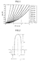
- FIG. 1 shows calculated values of a splicing loss with respect to an offset for a connection between the same type of SMF fibers.
- the offset is a key parameter for reducing the splicing loss between an optical fiber and a light source, between an optical fiber and a light receiving unit, or between optical fibers. Since the maximum offset due to manufacturing error can be about 1 ⁇ m, the optical interconnection system must be designed to allow a 1 ⁇ m offset, in light of worst case design.
- the optical fiber with an MFD of 4 ⁇ m causes a splicing loss of about 1.1 dB for an offset of 1 ⁇ m, If there are ten connections between a light source, VCSEL and an optical receiver and an offset of 1 ⁇ m occurs at each connection, then a splicing loss due to the offset is up to 11 dB. If a typical optical interconnection system with a VCSEL output power of -3 dBm, a receiver sensitivity of -16 dBm, and a fiber length of not less than 50 cm is built, a dynamic range of the system is about 13 dB since the transmission losses at other than the bended potions of the fiber is as low as not less than 0.01 dB.
- the splicing loss essentially includes a loss due to an angular offset at each connection, in addition to 11 dB due to the axis offset.
- this assumed system has few margins for a dynamic range of 13 dB. Therefore, the use of an SMF fiber with an MFD of not more than 4 ⁇ m makes it difficult to build the optical interconnection system with especially the above parameters.
- the fiber is required to allow flexible wiring and compact storage. If a high-speed optical interconnection system is build using such a fiber, the transmission loss of the fiber is desirably almost zero. In other words, the optical fibers for optical interconnection are required to have no bending loss even when bent with a small curvature radius in wiring. In actual optical wiring in equipment, it is expected that a curvature radius of about 1 mm be added to several portions of the wired fiber.
- the tolerance of bending loss is desirably not more than 1 dB when the fiber is bent with a curvature radius of 1 mm by one turn, in light of local bending of the fiber in wiring and worst case design. This conditional bending loss indicates excellent characteristics of the fiber and allows flexible optical wiring.
- turn in this description bent portion.
- One turn means a complete 360° turn of optical fiber.
- four bent portions each of which is bent 90° in an optical fiber are collectively called “one turn”, and two 90° bent portions are collectively called “1/2 turn”.
- a normal SMF fiber when bent one turn with a curvature radius of 5 mm, has a bending loss of almost 30 dB at a wavelength of 1550 nm, and when bent one turn with a curvature radius of 1 mm, has a bending loss of not less than 60 dB at a wavelength of 1550 nm.
- a loss margin due to bending loss in the system with 13 dB dynamic range is as small as 2 dB, for example.
- the bending loss is required to be as small as not more than 1 dB per turn. Therefore, the normal SMF fiber cannot be used for such a system.
- a normal SMF fiber with a simple index profile since there is a trade-off between decreasing the bending loss and increasing the MFD, the bending loss and the splicing loss cannot be improved together.
- the fiber if wired in equipment, is required to be compactly stored, and may be also bent at many places in equipment with a small curvature radius of about 5 mm due to, for example, a slack of a wiring between chips, in addition to a curvature radius of about 1 mm as described above.
- the portions bent with a curvature radius of about 1 mm are heat-treated to relax a strain.
- bent portions each having a curvature radius of about 5 mm which cause at many places in equipment, are not subject to any specific treat like heat treatment.
- the fiber may be broken at bent portions each having a curvature radius of about 5 mm, by a stress strain. Accordingly, it is desirable to reduce the failure ratio due to bending.
- the more the diameter of cladding, the more the failure ratio and the strain of the optical fiber in bending Assume that an optical fiber used in an optical interconnection system has about twenty bent portions each having a curvature radius of about 5 mm and 90°. Let a screening level be 2%, a fatigue factor between the fiber and the coating material be 22, and a product lifetime be 5 years, then the failure rate of a fiber with a cladding diameter of 125 ⁇ m is 5.5. However, the failure rate of a fiber with a cladding diameter of 90 ⁇ m goes down to 0.04, i.e., about 0.7% of that of the fiber with a cladding diameter of 125 ⁇ m. For system design, the failure rate is preferably not more than 0.05. A normal optical fiber does not have an overwhelming need to reduce the failure ratio due to bending. However, it is very effective for the fiber bent with a small diameter as is used in an optical interconnection system to reduce the failure ratio.
- the SMF fiber is generally known as having an adverse effect on loss if it has a diameter of cladding not more than ten times the MFD. For this reason, the fiber actually used, which requires an MFD of not lees than 4 ⁇ m, requires a diameter of cladding of at least not less than 40 ⁇ m.
- Example 1 a simulation resulted in characteristics of a silica-based optical fiber of the present invention with a W-shaped profile as shown in FIG. 2 .
- This fiber includes a first layer (first core) in which germanium is doped and a depressed layer (second core) in which fluorine is doped.
- first core germanium
- second core depressed layer
- fluorine fluorine
- This fiber had an MFD of 5.1 ⁇ m at a wavelength of 1100 nm, operated at the same wavelength as a single mode fiber, and had a bending loss of 0.8 dB per turn with a curvature radius of 1 mm at the same wavelength.
- Another simulation on various parameters for the optical fiber with the W-shaped profile of FIG. 2 resulted in characteristics shown in the columns of Fibers A1 to A6 in Table 1. Referring to A and A1 to A6 in Table 1, Fiber A, A2, A4, and A6 have an MFD of not less than 4 ⁇ m at a wavelength of 1100 nm, allow single mode transmission, and have a bending loss of not more than 1 dB per turn at a wavelength of 1100 nm.
- the fibers with the W-shaped profile as shown in FIG. 2 if having a relative refractive index difference of the first core ( ⁇ 1) of not less than 0.5%, ⁇ of not less than 1.5, and a relative refractive index difference of the second core ( ⁇ 2) of not more than -0.2%, can be provided as desired.
- Example 2 a simulation resulted in characteristics of a silica-based optical fiber of the present invention with a W-segmented profile as shown in FIG. 4 .
- This fiber includes a first layer (first core) in which germanium is doped, a depressed layer (second core) in which fluorine is doped, and a segment layer (third core) in which germanium is doped.
- first core germanium is doped
- second core depressed layer
- third core segment layer
- This fiber had an MFD of 5.2 ⁇ m at a wavelength of 1100 nm, operated at the same wavelength as a single mode fiber, and had a bending loss of 0.9 dB per turn with a curvature radius of 1 mm at the same wavelength.
- Another simulation on various parameters for the optical fiber with the W-segmented profile of FIG. 4 resulted in characteristics shown in the columns of Fibers C1 to C8 in Table 1. Referring to C and C1 to C8 in Table 1, Fibers C, C2, C4, and C6 have an MFD of not less than 4 ⁇ m at a wavelength of 1100 nm, allow single mode transmission, and have a bending loss of not more than 1 dB per turn at a wavelength of 1100 nm.
- the fibers with the W-segmented profile as shown in FIG. 4 if having a relative refractive index difference of the first core ( ⁇ 1) of not less than 0.5%, ⁇ of not less than 1.5, a relative refractive index difference of the second core ( ⁇ 2) of not more than -0.2%, and a relative refractive index difference of the third core ( ⁇ 3) of not less than 0.2%, can be provided as desired.
- Example 3 a simulation resulted in characteristics of a silica-based optical fiber of the present invention with a quasi-W-shaped profile as shown in FIG. 5 .
- This fiber includes a first layer (first core) in which germanium is doped, a silica layer (second core), and a depressed layer (third core) in which fluorine is doped.
- first core germanium
- second core silica layer
- third core depressed layer
- ⁇ 3 is a relative refractive index difference of the third core with respect to the cladding, represented by expression (4).
- n c3 in expression (4) is the minimum refractive-index of the third core on the quasi-W-shaped profile.
- This fiber had an MFD of 5.0 ⁇ m at a wavelength of 1100 nm, operated at the same wavelength as a single mode fiber, and had a bending loss of 0.7 dB per turn with a curvature radius of 1 mm at the same wavelength.
- Another simulation on various parameters for the optical fiber with the quasi-W-shaped profile of FIG. 5 resulted in characteristics shown in the columns of Fibers D1 to D6 in Table 1. Referring to D and D1 to D6 in Table 1, Fibers D, D2, D4, and D6 have an MFD of not less than 4 ⁇ m at a wavelength of 1100 nm, allow single mode transmission, and have a bending loss of not more than 1 dB per turn at a wavelength of 1100 nm.
- the fibers with the quasi-W-shaped profile as shown in FIG. 5 if having a relative refractive index difference of the first core ( ⁇ 1) of not less than 0.5%, ⁇ of not less than 1.5, a relative refractive index difference of the second core ( ⁇ 2) of substantially 0%, and a relative refractive index difference of the third core ( ⁇ 3) of not more than -0.2%, can be provided as desired.
- SMF fibers with a simple index profile if having the same MFD, have the same bending loss regardless of core profile when the cutoff wavelength is determined by changing the core diameter.
- the fibers with the W-shaped profile in which the depressed layer is provided over the first core as the second core can have variable MFDs at the same bending loss and cutoff wavelength as those of the fibers with the simple index profile. This is because the depressed layer causes no red-shift of the cutoff wavelength even if the relative refractive index difference ( ⁇ ) of the centered core is increased, thereby there is no need for reducing the core diameter.
- the profile of the first core has a substantial impact on the MFD.
- MFD is not so influenced by the relative refractive index difference ( ⁇ ) or the width of the depressed layer.
- Optical fibers are sometimes used in ribbon form for optical interconnection.
- the optical fiber ribbon allows multichannel optical transmission and high-speed optical communication.
- a coated silica glass optical fiber generally has an outer-diameter of 250 ⁇ m for a cladding diameter of 125 ⁇ m, and an optical fiber ribbon including a plurality of fibers bonded in parallel to each other typically has a pitch of 250 ⁇ m.
- the narrow-pitch fiber ribbon using small-diameter fibers is more flexible in wiring, allows space-saving storage, and is an optical element suitable for optical interconnection.
- FIG. 6 shows a configuration of an optical interconnection system using an optical fiber ribbon including the optical fiber according to the present invention as a transmission medium.
- the optical interconnection system shown in FIG. 6 uses a VCSEL with an emission wavelength of 1100 nm as a light source, and further includes a backboard 3 and a printed circuit board 2 connected to the backboard 3 through connectors 4.
- optic input/output devices 1 are mounted, and are connected to the connectors 4 through small-diameter fiber ribbons 5 as described above.
- the small-diameter fiber ribbons 5 also are laid out on the backboard 3, thereby allowing optical connection between optical interconnection systems.
- Example 1 The optical fiber in Example 1 (Fiber A in Table 1) was actually manufactured so that its cladding diameter would be 80 ⁇ m.
- Table 2 shows detailed parameters of the refractive index profiles and optical characteristics of the manufactured fiber. The optical fiber with characteristics almost as simulated was obtained.
- Table2 CHARACTERISTICS OF TEST FIBBER (a)STRUCTURAL PARAMETERS ⁇ 1 ⁇ 1 ⁇ 2 a/ ⁇ m b/ ⁇ m 0.9 1.9 -0.4 7.5 10.2 (b) OPTICAL CHARACTERISTICS ⁇ c/nm MFD/ ⁇ m (1100nm) MFD/ ⁇ m (1200nm) BENDING LOSS/dB 1100nm,1TURN BENDING LOSS/dB 1200nm,1TURN 1085 5.1 5.3 0.9 1.3
- Fiber A has a W-shaped profile, and its MFD increases and its effective refractive index decreases, as the wavelength is long. Therefore, the MFD at a wavelength of 1200 nm is more than that at a wavelength of 1100 nm, whereas the bending loss at a wavelength of 1200 nm is more than that at a wavelength of 1100 nm.
- the loss margin of bending loss be 5 dB, bending tolerance is up to 5 turns with a curvature radius of 1 mm at a wavelength of 1100 nm. At a wavelength of 1200 nm, bending tolerance is up to 4 turns with a curvature radius of 1 mm.
- An optical fiber ribbon was actually manufactured using the optical fiber shown in Table 2, and an optical interconnection system was actually built using the manufactured optical fiber ribbon and a VCSEL with an emission wavelength of 1200 nm, which is the same as the configuration shown in FIG. 6 .
- ultraviolet curing resin was used as the material of the coating resin 21, ultraviolet curing resin was used.
- the pitch P can be as small as 60 ⁇ m if an optical fiber with a cladding diameter of 40 ⁇ m and a difference between the outer diameter of the coating and the outer diameter of the cladding of 20 ⁇ m is used.
- the finished optical fiber ribbon 20 was 1.55 mm in width W and 0.17 mm in thickness H. If the VCSEL to be connected to the fiber ribbon is a twelve-channel laser array with a pitch of 125 ⁇ m, the manufactured fiber ribbon 20 allows multiple optical connection. In this configuration, a directly modulated VCSEL allows super high-speed optical connection over 100 Gbps.
- the optical fiber according to Examples allows single mode transmission at a wavelength of 1100 nm and a VCSEL with an emission wavelength of 1100 nm may be used in an optical interconnection system, whereas the VCSEL with an emission wavelength of 1200 nm was used in Examples.
- a flame retardant ribbon was manufactured using flame retardant ultraviolet curing urethane acrylate resin as ultraviolet curing resin for the material of the coating resin 21.
- the flame retardant ultraviolet curing urethane acrylate resin was made as follows. Addition of (1) Halogen additive such as bromine or chlorine, (2) antimony compound such as antimony trioxide or triphenylethylene antimony, (3) metallic hydrate such as aluminium hydroxide or magnesium hydroxide, or (4) phosphorus compound such as phosphate ester, to resin is examined to obtain flame retardant resin. Moreover, halogenation of prepolymer of which ultraviolet curing resin consists or acrylic monomer with bromine or chlorine, and further addition of phosphorus are examined to obtain flame retardant resin. Among these processes, addition of bromine-based flame retardant to resin was found effective in flame retardant.
- An optical fiber ribbon obtained using ultraviolet curing urethane acrylate resin including flame retardant to prepare ultraviolet curing resin for ribbon was evaluated by a 60° inclined flame test conforming to JIS C3005. As a result, the flame added to the fiber was quenched spontaneously in an average of about 3.2 sec, which satisfies JIS C3005.
- Thermoplastic flame retardant resin may be used instead of flame retardant ultraviolet curing resin in Examples.
- the flame added to the fiber was quenched spontaneously in an average of 5.7 sec, which satisfies UL1581 without burned dropping.
- the flame added to the fiber was quenched spontaneously in an average of 7.6 sec, and the wire and a ribbon had both good flame retardant.
- Thermoplastic flame retardant resin may be used instead of flame retardant ultraviolet curing resin in Examples.
- the invention further relates to the following embodiments which are part of the description. Advantageous features of different embodiments can be combined with each other in one embodiment. It is further possible to omit one or more features from a specific embodiment. The omitted one or more features are not necessary for the specific embodiment.
Landscapes
- Physics & Mathematics (AREA)
- General Physics & Mathematics (AREA)
- Optics & Photonics (AREA)
- Optical Couplings Of Light Guides (AREA)
- Optical Fibers, Optical Fiber Cores, And Optical Fiber Bundles (AREA)
- Glass Compositions (AREA)
Applications Claiming Priority (4)
| Application Number | Priority Date | Filing Date | Title |
|---|---|---|---|
| JP2004234557 | 2004-08-11 | ||
| JP2005185166 | 2005-06-24 | ||
| JP2005197894A JP4444177B2 (ja) | 2004-08-11 | 2005-07-06 | 光ファイバ、光ファイバテープおよび光インターコネクションシステム |
| EP05017425A EP1628149A1 (de) | 2004-08-11 | 2005-08-10 | Optische Faser, optisches Faserbändchen und optisches Verbindungssystem |
Related Parent Applications (1)
| Application Number | Title | Priority Date | Filing Date |
|---|---|---|---|
| EP05017425A Division EP1628149A1 (de) | 2004-08-11 | 2005-08-10 | Optische Faser, optisches Faserbändchen und optisches Verbindungssystem |
Publications (2)
| Publication Number | Publication Date |
|---|---|
| EP2017660A2 true EP2017660A2 (de) | 2009-01-21 |
| EP2017660A3 EP2017660A3 (de) | 2009-11-18 |
Family
ID=35207723
Family Applications (2)
| Application Number | Title | Priority Date | Filing Date |
|---|---|---|---|
| EP05017425A Withdrawn EP1628149A1 (de) | 2004-08-11 | 2005-08-10 | Optische Faser, optisches Faserbändchen und optisches Verbindungssystem |
| EP08167146A Ceased EP2017660A3 (de) | 2004-08-11 | 2005-08-10 | Optische Faser, optisches Faserband und optisches Verbindungssystem |
Family Applications Before (1)
| Application Number | Title | Priority Date | Filing Date |
|---|---|---|---|
| EP05017425A Withdrawn EP1628149A1 (de) | 2004-08-11 | 2005-08-10 | Optische Faser, optisches Faserbändchen und optisches Verbindungssystem |
Country Status (3)
| Country | Link |
|---|---|
| US (1) | US7295741B2 (de) |
| EP (2) | EP1628149A1 (de) |
| JP (1) | JP4444177B2 (de) |
Families Citing this family (38)
| Publication number | Priority date | Publication date | Assignee | Title |
|---|---|---|---|---|
| JP4444177B2 (ja) | 2004-08-11 | 2010-03-31 | 古河電気工業株式会社 | 光ファイバ、光ファイバテープおよび光インターコネクションシステム |
| JP4477555B2 (ja) * | 2005-03-01 | 2010-06-09 | 古河電気工業株式会社 | 光ファイバおよび光インターコネクションシステム |
| JP4163187B2 (ja) * | 2005-03-24 | 2008-10-08 | 古河電気工業株式会社 | 光伝送体の配線方法および光インターコネクションシステム |
| FR2893149B1 (fr) | 2005-11-10 | 2008-01-11 | Draka Comteq France | Fibre optique monomode. |
| JP4460065B2 (ja) * | 2006-02-21 | 2010-05-12 | 古河電気工業株式会社 | 非線形光ファイバおよび非線形光デバイスならびに光信号処理装置 |
| FR2899693B1 (fr) | 2006-04-10 | 2008-08-22 | Draka Comteq France | Fibre optique monomode. |
| JP2008058662A (ja) * | 2006-08-31 | 2008-03-13 | Furukawa Electric Co Ltd:The | 光ファイバおよび光ファイバテープならびに光インターコネクションシステム |
| JP2008058664A (ja) * | 2006-08-31 | 2008-03-13 | Furukawa Electric Co Ltd:The | 光ファイバおよび光ファイバテープならびに光インターコネクションシステム |
| JP2008058663A (ja) * | 2006-08-31 | 2008-03-13 | Furukawa Electric Co Ltd:The | 光ファイバおよび光ファイバテープならびに光インターコネクションシステム |
| JP2008090040A (ja) * | 2006-10-03 | 2008-04-17 | Furukawa Electric Co Ltd:The | 光ファイバテープ心線 |
| US7975699B2 (en) | 2007-10-30 | 2011-07-12 | The Invention Science Fund I, Llc | Condoms configured to facilitate release of nitric oxide |
| US8221690B2 (en) | 2007-10-30 | 2012-07-17 | The Invention Science Fund I, Llc | Systems and devices that utilize photolyzable nitric oxide donors |
| US8642093B2 (en) | 2007-10-30 | 2014-02-04 | The Invention Science Fund I, Llc | Methods and systems for use of photolyzable nitric oxide donors |
| US7862598B2 (en) | 2007-10-30 | 2011-01-04 | The Invention Science Fund I, Llc | Devices and systems that deliver nitric oxide |
| JP4452756B2 (ja) | 2007-03-05 | 2010-04-21 | 株式会社フジクラ | フォトニックバンドギャップファイバ |
| EP2120073B1 (de) | 2007-03-05 | 2011-09-28 | Fujikura, Ltd. | Faser mit photonischem bandabstand |
| US10080823B2 (en) | 2007-10-30 | 2018-09-25 | Gearbox Llc | Substrates for nitric oxide releasing devices |
| US8980332B2 (en) | 2007-10-30 | 2015-03-17 | The Invention Science Fund I, Llc | Methods and systems for use of photolyzable nitric oxide donors |
| US8877508B2 (en) | 2007-10-30 | 2014-11-04 | The Invention Science Fund I, Llc | Devices and systems that deliver nitric oxide |
| US8349262B2 (en) | 2007-10-30 | 2013-01-08 | The Invention Science Fund I, Llc | Nitric oxide permeable housings |
| US7897399B2 (en) | 2007-10-30 | 2011-03-01 | The Invention Science Fund I, Llc | Nitric oxide sensors and systems |
| DK2206001T3 (da) | 2007-11-09 | 2014-07-07 | Draka Comteq Bv | Optisk fiber, der er modstandsdygtig over for mikrobøjning |
| US20090169163A1 (en) * | 2007-12-13 | 2009-07-02 | Abbott Iii John Steele | Bend Resistant Multimode Optical Fiber |
| JP5330729B2 (ja) * | 2008-04-16 | 2013-10-30 | 三菱電線工業株式会社 | グレーデッドインデックス形マルチモード光ファイバ |
| FR2930997B1 (fr) | 2008-05-06 | 2010-08-13 | Draka Comteq France Sa | Fibre optique monomode |
| WO2013031649A1 (ja) * | 2011-08-26 | 2013-03-07 | 株式会社フジクラ | 光ファイバ、光伝送路、及び、光ファイバの製造方法 |
| JP5958068B2 (ja) * | 2012-05-15 | 2016-07-27 | 住友電気工業株式会社 | マルチコア光ファイバ実装方法 |
| US10295734B2 (en) | 2016-05-17 | 2019-05-21 | Corning Incorporated | Optical fiber for both multimode and single-mode operation and transmission system therefor |
| JP7214352B2 (ja) | 2018-03-08 | 2023-01-30 | 古河電気工業株式会社 | 光ファイバ |
| EP3807684B1 (de) * | 2018-06-15 | 2024-09-18 | Corning Incorporated | Hochdichtes glasfaserband und bandkabelverbindungen mit glasfasern mit kleinem durchmesser |
| WO2020090742A1 (ja) | 2018-10-30 | 2020-05-07 | 古河電気工業株式会社 | 光ファイバ |
| WO2020095315A1 (en) * | 2018-11-05 | 2020-05-14 | Sterlite Technologies Limited | Matrix material for rollable optical fibre ribbons |
| JP7019617B2 (ja) * | 2019-02-07 | 2022-02-15 | 古河電気工業株式会社 | 光ファイバおよび光ファイバの製造方法 |
| JP7145814B2 (ja) * | 2019-05-27 | 2022-10-03 | 古河電気工業株式会社 | 光ファイバ |
| JP7145816B2 (ja) * | 2019-06-07 | 2022-10-03 | 古河電気工業株式会社 | マルチコアファイバ |
| JP7508233B2 (ja) * | 2020-02-04 | 2024-07-01 | 古河電気工業株式会社 | 光ファイバならびに光ファイバおよび光ファイバ母材の製造方法 |
| TWI789660B (zh) * | 2020-12-18 | 2023-01-11 | 財團法人工業技術研究院 | 軟性電子封裝裝置的製造方法 |
| US11378735B1 (en) | 2021-03-05 | 2022-07-05 | Furukawa Electric Co., Ltd. | Multi-core fiber |
Citations (1)
| Publication number | Priority date | Publication date | Assignee | Title |
|---|---|---|---|---|
| EP0938018A1 (de) * | 1997-08-27 | 1999-08-25 | Sumitomo Electric Industries, Ltd. | Nichtlineare optische faser, spule mit optischer faser und wellenlängenkonvertor |
Family Cites Families (9)
| Publication number | Priority date | Publication date | Assignee | Title |
|---|---|---|---|---|
| EP1141754B1 (de) * | 1998-12-18 | 2008-09-03 | Prysmian Cavi e Sistemi Energia S.r.l. | Optische faser für innerstädtische- und zugangs-netzwerksysteme |
| EP1116970A1 (de) * | 1999-06-28 | 2001-07-18 | The Furukawa Electric Co., Ltd. | Optische übertragungsstrecke |
| US20020163688A1 (en) * | 2001-03-26 | 2002-11-07 | Zuhua Zhu | Optical communications system and vertical cavity surface emitting laser therefor |
| US6771865B2 (en) * | 2002-03-20 | 2004-08-03 | Corning Incorporated | Low bend loss optical fiber and components made therefrom |
| CN1653370A (zh) | 2002-05-17 | 2005-08-10 | 住友电气工业株式会社 | 带状光纤心线、其制造方法、含带状心线连接器、含带状心线光纤阵列、以及光布线系统 |
| WO2004019089A2 (en) * | 2002-05-31 | 2004-03-04 | Corning Incorporated | Low macrobending loss optical fiber |
| US6888993B2 (en) * | 2002-11-27 | 2005-05-03 | Corning Incorporated | Dispersion compensating optical fiber for SMF and transmission link including same |
| US7187833B2 (en) * | 2004-04-29 | 2007-03-06 | Corning Incorporated | Low attenuation large effective area optical fiber |
| JP4444177B2 (ja) | 2004-08-11 | 2010-03-31 | 古河電気工業株式会社 | 光ファイバ、光ファイバテープおよび光インターコネクションシステム |
-
2005
- 2005-07-06 JP JP2005197894A patent/JP4444177B2/ja not_active Expired - Fee Related
- 2005-08-10 EP EP05017425A patent/EP1628149A1/de not_active Withdrawn
- 2005-08-10 US US11/200,100 patent/US7295741B2/en not_active Expired - Fee Related
- 2005-08-10 EP EP08167146A patent/EP2017660A3/de not_active Ceased
Patent Citations (1)
| Publication number | Priority date | Publication date | Assignee | Title |
|---|---|---|---|---|
| EP0938018A1 (de) * | 1997-08-27 | 1999-08-25 | Sumitomo Electric Industries, Ltd. | Nichtlineare optische faser, spule mit optischer faser und wellenlängenkonvertor |
Non-Patent Citations (2)
| Title |
|---|
| F. KOYAMA ET AL.: "Data Transmission Over Single-Mode Fiber by Using 1.2 Uncooled GaInAs/GaAs Laser for Gb/s Local Area Network", PHOTONICS TECHNOLOGY LETTERS, vol. 12, no. 2, February 2000 (2000-02-01), pages 125 - 127, XP000912629, DOI: doi:10.1109/68.823491 |
| GAIN F. KOYAMA ET AL.: "1.2 pm highly strained GaInAs/GaAs quantum well lasers for single-mode fibre datalink", ELECTRONICS LETTERS, vol. 35, no. 13, June 1999 (1999-06-01), pages 1079 - 1081 |
Also Published As
| Publication number | Publication date |
|---|---|
| US20060034575A1 (en) | 2006-02-16 |
| EP2017660A3 (de) | 2009-11-18 |
| US7295741B2 (en) | 2007-11-13 |
| JP2007033466A (ja) | 2007-02-08 |
| EP1628149A1 (de) | 2006-02-22 |
| JP4444177B2 (ja) | 2010-03-31 |
Similar Documents
| Publication | Publication Date | Title |
|---|---|---|
| US7295741B2 (en) | Optical fiber, optical fiber ribbon, and optical interconnection system | |
| US7574088B2 (en) | Optical fiber and optical fiber ribbon, and optical interconnection system | |
| US11480727B2 (en) | Multi-core optical fiber | |
| US7583878B2 (en) | Optical fiber, optical fiber ribbon, and optical interconnection system | |
| US7878712B2 (en) | Optical fiber, optical fiber ribbon, and optical interconnection system | |
| CN101356460B (zh) | 光纤、光纤带及光互连系统 | |
| EP1698920B1 (de) | Glasfaser- und optisches Verbindungssystem | |
| US20090148112A1 (en) | Optical fiber | |
| KR20170047217A (ko) | 저소모 소량 모드 광섬유 | |
| JPWO2010119930A1 (ja) | マルチコア光ファイバ | |
| WO2019138848A1 (en) | Optical fiber, coated optical fiber, and optical transmission system | |
| KR20060110311A (ko) | 중간 분산 nzdsf를 위한 분산 보상 섬유 및 이를이용한 전송 장치 | |
| US20090060432A1 (en) | Light transmitting body and optical interconnection system | |
| CN100545684C (zh) | 光纤及光学互连系统 | |
| CN100424530C (zh) | 光纤、光纤带以及光互连系统 |
Legal Events
| Date | Code | Title | Description |
|---|---|---|---|
| PUAI | Public reference made under article 153(3) epc to a published international application that has entered the european phase |
Free format text: ORIGINAL CODE: 0009012 |
|
| 17P | Request for examination filed |
Effective date: 20081021 |
|
| AC | Divisional application: reference to earlier application |
Ref document number: 1628149 Country of ref document: EP Kind code of ref document: P |
|
| AK | Designated contracting states |
Kind code of ref document: A2 Designated state(s): DE GB |
|
| PUAL | Search report despatched |
Free format text: ORIGINAL CODE: 0009013 |
|
| AK | Designated contracting states |
Kind code of ref document: A3 Designated state(s): DE GB |
|
| AKX | Designation fees paid |
Designated state(s): DE GB |
|
| 17Q | First examination report despatched |
Effective date: 20160523 |
|
| STAA | Information on the status of an ep patent application or granted ep patent |
Free format text: STATUS: THE APPLICATION HAS BEEN REFUSED |
|
| 18R | Application refused |
Effective date: 20180109 |