EP2017804A1 - Funktionsweise eines Befehlsgebers in einer Heiminstallation und Befehlsgeber für seine Aktivierung - Google Patents
Funktionsweise eines Befehlsgebers in einer Heiminstallation und Befehlsgeber für seine Aktivierung Download PDFInfo
- Publication number
- EP2017804A1 EP2017804A1 EP08160402A EP08160402A EP2017804A1 EP 2017804 A1 EP2017804 A1 EP 2017804A1 EP 08160402 A EP08160402 A EP 08160402A EP 08160402 A EP08160402 A EP 08160402A EP 2017804 A1 EP2017804 A1 EP 2017804A1
- Authority
- EP
- European Patent Office
- Prior art keywords
- key
- protocol
- operating method
- transmitter
- configuration
- Prior art date
- Legal status (The legal status is an assumption and is not a legal conclusion. Google has not performed a legal analysis and makes no representation as to the accuracy of the status listed.)
- Withdrawn
Links
- 238000011017 operating method Methods 0.000 title claims description 17
- 238000009434 installation Methods 0.000 title description 4
- 238000004891 communication Methods 0.000 claims abstract description 17
- 238000000034 method Methods 0.000 claims abstract description 7
- 238000003825 pressing Methods 0.000 claims description 13
- 238000012986 modification Methods 0.000 claims 1
- 230000004048 modification Effects 0.000 claims 1
- 230000009471 action Effects 0.000 abstract description 8
- 230000008859 change Effects 0.000 description 11
- 230000004913 activation Effects 0.000 description 9
- 230000000007 visual effect Effects 0.000 description 8
- 230000005540 biological transmission Effects 0.000 description 5
- 230000004397 blinking Effects 0.000 description 5
- 230000002457 bidirectional effect Effects 0.000 description 4
- 238000010586 diagram Methods 0.000 description 4
- 230000001419 dependent effect Effects 0.000 description 2
- 238000012423 maintenance Methods 0.000 description 2
- 230000008901 benefit Effects 0.000 description 1
- 238000012508 change request Methods 0.000 description 1
- 239000003086 colorant Substances 0.000 description 1
- 238000010276 construction Methods 0.000 description 1
- 238000013479 data entry Methods 0.000 description 1
- 238000003745 diagnosis Methods 0.000 description 1
- 230000004069 differentiation Effects 0.000 description 1
- 238000004519 manufacturing process Methods 0.000 description 1
- 230000008569 process Effects 0.000 description 1
- 230000004044 response Effects 0.000 description 1
- 230000000717 retained effect Effects 0.000 description 1
- 230000000475 sunscreen effect Effects 0.000 description 1
- 239000000516 sunscreening agent Substances 0.000 description 1
- 238000012360 testing method Methods 0.000 description 1
Images


Classifications
-
- H—ELECTRICITY
- H04—ELECTRIC COMMUNICATION TECHNIQUE
- H04L—TRANSMISSION OF DIGITAL INFORMATION, e.g. TELEGRAPHIC COMMUNICATION
- H04L12/00—Data switching networks
- H04L12/28—Data switching networks characterised by path configuration, e.g. LAN [Local Area Networks] or WAN [Wide Area Networks]
- H04L12/2803—Home automation networks
- H04L12/2807—Exchanging configuration information on appliance services in a home automation network
- H04L12/281—Exchanging configuration information on appliance services in a home automation network indicating a format for calling an appliance service function in a home automation network
-
- E—FIXED CONSTRUCTIONS
- E06—DOORS, WINDOWS, SHUTTERS, OR ROLLER BLINDS IN GENERAL; LADDERS
- E06B—FIXED OR MOVABLE CLOSURES FOR OPENINGS IN BUILDINGS, VEHICLES, FENCES OR LIKE ENCLOSURES IN GENERAL, e.g. DOORS, WINDOWS, BLINDS, GATES
- E06B9/00—Screening or protective devices for wall or similar openings, with or without operating or securing mechanisms; Closures of similar construction
- E06B9/56—Operating, guiding or securing devices or arrangements for roll-type closures; Spring drums; Tape drums; Counterweighting arrangements therefor
- E06B9/68—Operating devices or mechanisms, e.g. with electric drive
-
- G—PHYSICS
- G08—SIGNALLING
- G08C—TRANSMISSION SYSTEMS FOR MEASURED VALUES, CONTROL OR SIMILAR SIGNALS
- G08C17/00—Arrangements for transmitting signals characterised by the use of a wireless electrical link
- G08C17/02—Arrangements for transmitting signals characterised by the use of a wireless electrical link using a radio link
Definitions
- the invention relates to a command transmitter in a home automation system comprising actuators for the motorized operation of screens or openings such as shutters, windows, doors, screens for sunscreen or projection.
- Such issuers translate an action of a user on a control interface comprising for example buttons or buttons, in a movement order and transmit this order to an actuator.
- the order is contained in information sent by the issuer.
- the transmission of information can be done wired or wireless, including radio waves.
- the set of characteristics of this transmission of information is part of a communication protocol that determines how to communicate to be understood from another object of the home automation set.
- object is used in this application to designate indifferently or according to the context an issuer of orders or a receiver of orders.
- the communication protocol also defines inter alia the radio frequency of information transmission and the construction of the frames constituting the information signals.
- Some products are available on the market, for which it is possible to select a protocol or another but without any feedback to the active protocol other than the good or bad operation of the protocol. the issuer of orders in the installation concerned.
- the command transmitter comprises a communication protocol selector, the position of the selector then indicates the active protocol.
- a sufficiently sophisticated interface is necessary to meet both a need for input and visual feedback.
- the protocol selection function is a rarely used function and it is generally sought to achieve it at the lowest cost by limiting the additional hardware resources.
- this solution is difficult to apply when different keys of a transmitter can each be configured with a specific protocol. It would then be necessary to multiply these visual and input interfaces.
- EP 1 756 786 a portable transmitter capable of transmitting communication signals according to two protocols, a so-called "unidirectional" protocol for managing communications in a unidirectional manner and a so-called “bidirectional" protocol for managing communications in a bidirectional manner.
- the selection of a protocol is done automatically: the transmitter sends initially a communication frame according to each protocol. If he receives a response to this signal, indicating that the object with which he communicates is able to receive signals according to the bidirectional protocol, it automatically switches to this protocol. Subsequent messages to this object will be made according to the bidirectional protocol. An appropriate display is then set up on a touch screen that self-configures according to the selected protocol. These display means must be developed to also allow the entry of control orders of the equipment.
- the object of the invention is to provide a method of operating an order transmitter overcoming the problems identified above and improving the operating methods known from the prior art.
- the invention proposes a method of operation that can be implemented by a command transmitter having a very simple structure, including very simple input and display means while providing tools for maintenance assistance.
- the invention also relates to a transmitter of orders for the implementation of such a method of operation.
- a command transmitter according to the invention is defined by claim 12.
- a command transmitter 1 comprises a box 2 provided with a user interface 3 comprising, for example, input keys 4 and a display interface 5, which may consist of a simple LED. Inside this housing 2 is an electronic unit 6.
- the electronic unit 6 comprises in particular a microprocessor 7.
- the input keys 4 are connected to inputs of the microprocessor 7.
- a module 8 for transmitting electromagnetic signals enabling to transmit commands is also linked to a microprocessor output 7.
- the module is for example a radio wave transmission module and is provided with an antenna 9. Alternatively, it may be a module of infrared emission.
- the electronic unit is powered by a battery or battery 10.
- the microprocessor also comprises software means for governing the operation of the command transmitter according to the invention.
- These software means include, for example, programs.
- the order transmitter is intended to be used with home automation equipment 20 comprising at least one actuator 21 of a screen 22 of shutter type, blind or door, window, garage door or gate. It can be used, more generally in a home automation system for remote control of home automation equipment.
- the home automation equipment is equipped with an electronic assembly 23 provided with an electromagnetic signal receiving module 24.
- an electromagnetic signal receiving module 24 may be a radio wave reception module connected to an antenna 25
- the receiving module operates according to the same communication protocol as the command transmitter 1.
- command transmitters and home automation devices can be able to receive or transmit signals according to a first protocol, a second protocol or both protocols.
- a communication protocol can be associated not with the issuer of orders as a whole, but with a key or some keys of this transmitter.
- a simple way of achieving this downward compatibility is to provide that the new ranges of transmitters can be configured according to one or other of the protocols at least manually.
- the command transmitter 1 comprises a protocol selection means 30, that is to say a means for configuring the one or more keys.
- This means makes it possible to configure the key or keys so that the command transmitter operates according to a first protocol during actions on one or more keys or according to a second protocol during actions on one or more keys.
- This selection means comprises a contact 30.
- the contact is located in the electronic unit 6. It is connected to the microprocessor 7.
- This contact 30 is arranged so as not to be operated inadvertently. It can be placed under a removable cover, for example a battery access cover (not shown). Each time this contact 30 is pressed, an active protocol indicator switches from one state to another.
- Each press on the contact causes the transmitter to switch over of a mode in which it transmits signals according to a first protocol to a mode in which it transmits signals according to another protocol.
- the user can not know, in view of the simple contact, according to which protocol the transmitter emits signals.
- This contact may possibly be common to other functions, for example a setting in programming mode or even to input keys 4, the differentiation between the setting function and / or active protocol indication and other functions carrying on the durations or sequences of supports.
- switching from one protocol to another could be effective at each new placement of the batteries.
- the active protocol information is not translated by visible information at the protocol selection means.
- the electronic unit When pressing one of the input keys of the command transmitter, the electronic unit translates this support into a signal that is emitted by the radio transmission module.
- the home automation device receives this signal, it decrypts it and, if it is intended for it, translates this signal into an action or a command of the apparatus.
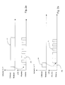
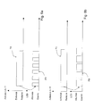
- the figure 2a illustrates the operation of the products of the prior art when pressing T on a key input.
- This support is accompanied, from the beginning of the support, a visual feedback such as fast flashing F1 of the light emitting diode of the display interface 5. This blinking lasts for a predetermined period or preferentially the support time of the input key.
- the issuer of orders and the home automation equipment or the electronic assembly of the equipment are prerequisite, that is to say that they exchange at least one identifier that is characteristic of their relationship.
- This identifier is registered, during a pairing procedure, at the level of one and / or the other of the communicating objects.
- the figure 2b illustrates the operation of the prior art during the configuration of the active protocol.
- no feedback F0 is proposed.
- F1 feedback in the form of a fast flash indicates to the user that its transmitter is in protocol change mode. This flickering F1 stops after a predetermined time, the transmitter is then configured.
- the user has no indication of the protocol thus chosen. Only on-site tests with different devices whose protocol is known may possibly make it possible to determine the active protocol.
- the command transmitter according to the invention allows feedback on the active protocol, only from existing interfaces.
- the nature of the feedback is characteristic of the protocol. For example, a fast or slow flash of a light emitting diode signals a first or a second protocol. Alternatively, a blinking and no signal signal a first or second protocol. Other forms of feedback can obviously be provided without departing from the scope of the invention.
- the protocol selection means is used to translate the request of the information request user to the protocol configuration.
- the first is to issue a feedback signal during a particular action using the protocol selection means, still without additional hardware means, this particular action being differentiated from the protocol change action and the others. functions possibly available from this same means. For example, a short press, less than 2 seconds, causes the protocol switchover. A longer press t, for example greater than 2 seconds, or even greater than 3 seconds, causes the appearance of the information signal, without there being a change of protocol.
- the second option is to send the feedback signal indicating the protocol during the protocol switchover.
- the visual signal emitted as a result of the protocol change is representative of the protocol in which the transmitter has just been configured.
- the protocol used before this switchover is the other protocol. If there are more than two protocols, they can be configured successively in which case it is possible to know the previous states of the transmitter.
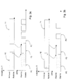
- FIGS. 3a and 3b illustrate the first option of the first embodiment in which the contact 30 is used both to cause protocol change and feedback.
- This function is particularly useful in the case where each input key controls a separate home automation equipment (for example by successive presses controlling ON / OFF state changes or MONTEE-STOP-DESCENTE) and thus the transmitter of orders can dialogue with different equipments according to different protocol.
- the protocol change is made when the contact 30 is released. If the contact 30 is nevertheless maintained for a longer duration, for example greater than 2 seconds, the electronic unit deduces that it is not a protocol change request but an information request. No feedback F0 therefore takes place during the first 2 seconds. At the end of these two seconds, the light-emitting diode is lit continuously in a format F2 for a predetermined duration or until a new pressing on one of the input keys T1 which one wants to know the associated protocol.
- a first feedback format F3 in the form of a fast flashing of the light emitting diode, slightly different from the flashing F1 described above is produced to signify that a first protocol is associated with the key, for the duration of press the T1 input key.
- the fast flashing F3 stops ( figure 3a ).
- a second feedback format F4 in the form of a slow flashing of the light emitting diode, different from the flashings F1 and F3 described above is produced to signify that a second protocol is associated with the key, for the duration of press the T1 input key.
- the slow flashing F4 stops ( figure 3b ).
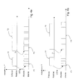
- FIGS. 4a and 4b illustrate the second option of the first embodiment wherein the contact 30 is used both to cause protocol change and feedback. These figures also show an information request by input key.
- This option differs from the previous one in that the activation times of the contact 30 are not managed, in other words, each activation, whatever its duration, modifies the active protocol, but also allows a feedback characterizing the new active protocol.
- the protocol change is made when releasing the contact.
- F1 format feedback (equivalent or different from the format F1 of the prior art) takes place from the beginning of the activation of the contact 30 and for a predetermined duration that may be equal to 2 seconds.
- the light-emitting diode After pressing one of the input keys T2 whose associated protocol is to be known, the light-emitting diode starts flashing in a new format F3 or F4 different from the previous F1. This blinking lasts for a predetermined time or as long as the T2 key is pressed.
- a first format F3 feedback in the form of a fast flashing of the light emitting diode, slightly different F1 flashing described above is produced to signify that a first protocol is associated with the key ( figure 4a ).
- a second feedback format F4 in the form of a slow flash of the light-emitting diode, different from the flashes F1 and F3 described above is produced to signify that a second protocol is associated with the key ( figure 4b ).
- the technician should note that the active protocol on site was equivalent not to the protocol of which it has the feedback of information following the maneuver carried out, but to the previous one.
- a particular advantage related to this embodiment option is the independence vis-à-vis the protocol change means. Indeed, it is applicable with other means, such as protocol switching to each change of batteries.
- the existing input keys are used to translate the request of the information request user on the protocol configuration.
- this second embodiment if there is a feedback related to the activation of an input key, it is retained during the activation of this key. However, a new feedback is provided later, either when the activation is maintained longer than a predetermined time, or for a predetermined time after releasing the key.
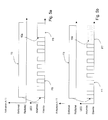
- FIGS. 5a and 5b illustrate the first option of this second embodiment used only for feedback and not dependent on how the protocol change is performed. It is also clear that in this embodiment an information request is used for a data entry key, although this is not limiting. Indeed, as in the previous embodiments, a single protocol could be common to all input keys, in which case the implementation is applicable from the activation of any of the input keys.
- Pressing a T3 input key causes as illustrated on the figure 5a an implementation of the order associated with this key when the command transmitter is placed in an installation comprising home automation equipment to be controlled. In all cases, pressing this key T3 causes the issuance of an order, whether it is received or not.
- This support is accompanied, from the beginning of the support, a visual feedback such as fast flashing F5 of the light emitting diode. This blinking lasts in the state of the art for a predetermined period or preferably the time of pressing the input key.
- the visual feedback changes from that moment onwards. continue for a predetermined period or until the key is released.
- a first feedback format F6 in the form of a continuous ignition of the light emitting diode, following the aforementioned flashing is produced to signify that a first protocol is active.
- the T3 key is released, the light emitting diode extinguishes ( figure 5a ).
- a second format F7 feedback in the form of a lack of blinking or ignition of the light emitting diode, means that a second protocol is active ( figure 5b ).
- this second protocol is an old protocol, this feedback format (F5 + F7) corresponding to the operation of the old transmitters. It is therefore only necessary to provide a new feedback for new transmitters when they are configured with a new protocol.
- Pressing a T3 input key causes as illustrated on the figure 6a an implementation of the order associated with this key when the command transmitter is placed in an installation comprising home automation equipment to be controlled. In all cases, pressing this key T3 causes the issuance of an order, whether it is received or not.
- This support is accompanied, from the beginning of the support, a visual feedback such as a first flash F8 of the light emitting diode in the case where a first protocol is linked to the key support. This flashing lasts for a predetermined period or preferably the time of pressing the input key.
- the support is accompanied, from the beginning of the support, a visual return in the form of a second flashing F9 slower of the light emitting diode in the case where a second protocol is linked to the support key.
- This flashing lasts for a predetermined period or preferably the time of pressing the input key.
- the first flashing F8 in this embodiment corresponds to the F1 flicker set up on the old transmitters when the first protocol is an old protocol.
- the feedback formats give an indication on a sequence number of the protocol.
- the number of flashes close to the light emitting diode indicates the sequence number of the active protocol.
- Different formats F10, F11, F12 are thus represented in figure 7 , to indicate a first, second or third protocol.
- the feedback could be given by different colors produced by one or more diodes.
Landscapes
- Engineering & Computer Science (AREA)
- Automation & Control Theory (AREA)
- Computer Networks & Wireless Communication (AREA)
- Structural Engineering (AREA)
- Signal Processing (AREA)
- Physics & Mathematics (AREA)
- General Physics & Mathematics (AREA)
- Architecture (AREA)
- Civil Engineering (AREA)
- Selective Calling Equipment (AREA)
Applications Claiming Priority (1)
| Application Number | Priority Date | Filing Date | Title |
|---|---|---|---|
| FR0705161A FR2919097B1 (fr) | 2007-07-17 | 2007-07-17 | Procede de fonctionnement d'un emetteur d'ordres dans une installation domotique et emetteur d'ordres pour sa mise en oeuvre |
Publications (1)
| Publication Number | Publication Date |
|---|---|
| EP2017804A1 true EP2017804A1 (de) | 2009-01-21 |
Family
ID=39269282
Family Applications (1)
| Application Number | Title | Priority Date | Filing Date |
|---|---|---|---|
| EP08160402A Withdrawn EP2017804A1 (de) | 2007-07-17 | 2008-07-15 | Funktionsweise eines Befehlsgebers in einer Heiminstallation und Befehlsgeber für seine Aktivierung |
Country Status (2)
| Country | Link |
|---|---|
| EP (1) | EP2017804A1 (de) |
| FR (1) | FR2919097B1 (de) |
Cited By (3)
| Publication number | Priority date | Publication date | Assignee | Title |
|---|---|---|---|---|
| WO2011023730A1 (de) * | 2009-08-31 | 2011-03-03 | Tridonic Gmbh & Co. Kg | Bediengerät mit anzeige |
| EP2337050A1 (de) * | 2009-12-18 | 2011-06-22 | Somfy SAS | Steuervorrichtung und Heimanlage, die mit einer solchen Vorrichtung ausgestattet ist |
| FR2985072A1 (fr) * | 2011-12-26 | 2013-06-28 | Franciaflex | Procede de gestion d'une installation domotique |
Citations (4)
| Publication number | Priority date | Publication date | Assignee | Title |
|---|---|---|---|---|
| WO2004029897A2 (fr) * | 2002-09-27 | 2004-04-08 | Thomson Licensing S.A. | Procede de commande de plusieurs appareils a l'aide d'un dispositif deporte, et dispositif deporte mettant en oeuvre le procede |
| US6812881B1 (en) * | 1999-06-30 | 2004-11-02 | International Business Machines Corp. | System for remote communication with an addressable target using a generalized pointing device |
| US6832076B2 (en) | 2002-02-11 | 2004-12-14 | The Chamberlain Group, Inc. | Audible diagnostic information apparatus and method |
| WO2005119621A1 (en) * | 2004-06-01 | 2005-12-15 | Koninklijke Philips Electronics N.V. | Multi-protocol remote control device |
-
2007
- 2007-07-17 FR FR0705161A patent/FR2919097B1/fr active Active
-
2008
- 2008-07-15 EP EP08160402A patent/EP2017804A1/de not_active Withdrawn
Patent Citations (5)
| Publication number | Priority date | Publication date | Assignee | Title |
|---|---|---|---|---|
| US6812881B1 (en) * | 1999-06-30 | 2004-11-02 | International Business Machines Corp. | System for remote communication with an addressable target using a generalized pointing device |
| US6832076B2 (en) | 2002-02-11 | 2004-12-14 | The Chamberlain Group, Inc. | Audible diagnostic information apparatus and method |
| WO2004029897A2 (fr) * | 2002-09-27 | 2004-04-08 | Thomson Licensing S.A. | Procede de commande de plusieurs appareils a l'aide d'un dispositif deporte, et dispositif deporte mettant en oeuvre le procede |
| WO2005119621A1 (en) * | 2004-06-01 | 2005-12-15 | Koninklijke Philips Electronics N.V. | Multi-protocol remote control device |
| EP1756786A1 (de) | 2004-06-01 | 2007-02-28 | Koninklijke Philips Electronics N.V. | Fernbedienungseinrichtung mit mehreren protokollen |
Cited By (4)
| Publication number | Priority date | Publication date | Assignee | Title |
|---|---|---|---|---|
| WO2011023730A1 (de) * | 2009-08-31 | 2011-03-03 | Tridonic Gmbh & Co. Kg | Bediengerät mit anzeige |
| EP2337050A1 (de) * | 2009-12-18 | 2011-06-22 | Somfy SAS | Steuervorrichtung und Heimanlage, die mit einer solchen Vorrichtung ausgestattet ist |
| FR2954576A1 (fr) * | 2009-12-18 | 2011-06-24 | Somfy Sas | Dispositif de commande et installation domotique comprenant un tel dispositif |
| FR2985072A1 (fr) * | 2011-12-26 | 2013-06-28 | Franciaflex | Procede de gestion d'une installation domotique |
Also Published As
| Publication number | Publication date |
|---|---|
| FR2919097A1 (fr) | 2009-01-23 |
| FR2919097B1 (fr) | 2010-07-30 |
Similar Documents
| Publication | Publication Date | Title |
|---|---|---|
| EP1816620B1 (de) | Kommunikationsverfahren zwischen einer Fernbedienung und Haushaltsgeräten über ein Relais | |
| EP1476859B1 (de) | Verfahren zur zuordnung bidirektionaler gegenständen | |
| EP2130100B1 (de) | Verfahren zum konfigurieren einer hausautomatisierungsinstallation und werkzeug zu seiner implementierung | |
| EP1699029B1 (de) | Verfahren zur Steuerung von Aktuatoren | |
| EP1476860B1 (de) | Verfahren zur Definition einer Gruppe zwischen bidirektionalen Objekten | |
| FR2859053A1 (fr) | Appareil seulement emetteur sans fil, emetteur de commande a distance d'un actionneur de barriere mobile et procede de selection d'une frequence d'emission pour un tel appareil | |
| EP2083408A2 (de) | Informationsübertragungsverfahren über Infrarotstrahlen zwischen einem Sender und einem Empfänger in einem Heimnetz | |
| FR2919097A1 (fr) | Procede de fonctionnement d'un emetteur d'ordres dans une installation domotique et emetteur d'ordres pour sa mise en oeuvre | |
| EP1253568B1 (de) | Verfahren und Vorrichtung zur Konfigurierung von Fernbedienungsgeräten | |
| EP1950722B1 (de) | Verfahren zur Konfiguration einer Befehlsübermittlungsanlage in einem Heimsystem | |
| EP2109086B1 (de) | Autonomer Befehlsgeber für Heimanlage | |
| EP4106270B1 (de) | Verfahren zur paarweisen zusammenlegung eines elektrischen geräts und entsprechende systeme | |
| EP1722340B1 (de) | Betriebsverfahren für eine Hausautomatisierungsanlage und zugehörige Hausautomatisierungsanlage | |
| FR2960086A1 (fr) | Procede de localisation d'une unite de commande d'un actionneur de manoeuvre d'un element de couverture de fenetre | |
| EP3531215B1 (de) | Funktionsverfahren für ein elektrisches laststeuermodul | |
| EP3023960B1 (de) | Motorisierte antriebsvorrichtung für eine heimanlage zum schliessen | |
| EP1469364B1 (de) | Verfahren zum Bilden einer Gruppe von Gliedern in einem Gebäudenetzwerk | |
| EP3543804A1 (de) | Verfahren zur steuerung einer haustechnikvorrichtung | |
| EP1783716B1 (de) | Verfahren zum Betrieb eines Gebäudenetzes, das eine Zeichengabeschnittstelle umfasst | |
| EP2958093B1 (de) | Funktionsverfahren einer steuervorrichtung, die eine änderung einer angezeigten grafischen darstellung in abhängigkeit von einem ausgewählten parameter ermöglicht | |
| FR2695238A1 (fr) | Procédé pour exploiter des signaux de télécommande, dispositif de télécommande, et unités fonctionnelles et installation s'y rapportant. | |
| FR2899348A1 (fr) | Procede de reconnaissance de moyens de commande informatique d'un dispositif de gestion et dispositif de gestion mettant en oeuvre ce procede | |
| FR3147656A1 (fr) | Procédé de configuration d’une installation domotique. | |
| EP2107802A1 (de) | Steuervorrichtung für mehrere Geräte mit Hilfe einer Infrarot-Fernsteuerung | |
| FR2877476A1 (fr) | Procede et dispositif de reception de commande |
Legal Events
| Date | Code | Title | Description |
|---|---|---|---|
| PUAI | Public reference made under article 153(3) epc to a published international application that has entered the european phase |
Free format text: ORIGINAL CODE: 0009012 |
|
| AK | Designated contracting states |
Kind code of ref document: A1 Designated state(s): AT BE BG CH CY CZ DE DK EE ES FI FR GB GR HR HU IE IS IT LI LT LU LV MC MT NL NO PL PT RO SE SI SK TR |
|
| AX | Request for extension of the european patent |
Extension state: AL BA MK RS |
|
| 17P | Request for examination filed |
Effective date: 20090717 |
|
| AKX | Designation fees paid |
Designated state(s): AT BE BG CH CY CZ DE DK EE ES FI FR GB GR HR HU IE IS IT LI LT LU LV MC MT NL NO PL PT RO SE SI SK TR |
|
| 17Q | First examination report despatched |
Effective date: 20090909 |
|
| STAA | Information on the status of an ep patent application or granted ep patent |
Free format text: STATUS: THE APPLICATION IS DEEMED TO BE WITHDRAWN |
|
| 18D | Application deemed to be withdrawn |
Effective date: 20170620 |