EP2017912A1 - Séparateur pour pile à combustible et son procédé de production - Google Patents
Séparateur pour pile à combustible et son procédé de production Download PDFInfo
- Publication number
- EP2017912A1 EP2017912A1 EP07737016A EP07737016A EP2017912A1 EP 2017912 A1 EP2017912 A1 EP 2017912A1 EP 07737016 A EP07737016 A EP 07737016A EP 07737016 A EP07737016 A EP 07737016A EP 2017912 A1 EP2017912 A1 EP 2017912A1
- Authority
- EP
- European Patent Office
- Prior art keywords
- fuel cell
- cell separator
- sheet
- preform
- phenol resin
- Prior art date
- Legal status (The legal status is an assumption and is not a legal conclusion. Google has not performed a legal analysis and makes no representation as to the accuracy of the status listed.)
- Withdrawn
Links
Images


Classifications
-
- H—ELECTRICITY
- H01—ELECTRIC ELEMENTS
- H01M—PROCESSES OR MEANS, e.g. BATTERIES, FOR THE DIRECT CONVERSION OF CHEMICAL ENERGY INTO ELECTRICAL ENERGY
- H01M8/00—Fuel cells; Manufacture thereof
- H01M8/02—Details
- H01M8/0202—Collectors; Separators, e.g. bipolar separators; Interconnectors
- H01M8/0204—Non-porous and characterised by the material
- H01M8/0221—Organic resins; Organic polymers
-
- H—ELECTRICITY
- H01—ELECTRIC ELEMENTS
- H01M—PROCESSES OR MEANS, e.g. BATTERIES, FOR THE DIRECT CONVERSION OF CHEMICAL ENERGY INTO ELECTRICAL ENERGY
- H01M8/00—Fuel cells; Manufacture thereof
- H01M8/02—Details
-
- B—PERFORMING OPERATIONS; TRANSPORTING
- B29—WORKING OF PLASTICS; WORKING OF SUBSTANCES IN A PLASTIC STATE IN GENERAL
- B29C—SHAPING OR JOINING OF PLASTICS; SHAPING OF MATERIAL IN A PLASTIC STATE, NOT OTHERWISE PROVIDED FOR; AFTER-TREATMENT OF THE SHAPED PRODUCTS, e.g. REPAIRING
- B29C43/00—Compression moulding, i.e. applying external pressure to flow the moulding material; Apparatus therefor
- B29C43/02—Compression moulding, i.e. applying external pressure to flow the moulding material; Apparatus therefor of articles of definite length, i.e. discrete articles
- B29C43/021—Compression moulding, i.e. applying external pressure to flow the moulding material; Apparatus therefor of articles of definite length, i.e. discrete articles characterised by the shape of the surface
-
- B—PERFORMING OPERATIONS; TRANSPORTING
- B29—WORKING OF PLASTICS; WORKING OF SUBSTANCES IN A PLASTIC STATE IN GENERAL
- B29C—SHAPING OR JOINING OF PLASTICS; SHAPING OF MATERIAL IN A PLASTIC STATE, NOT OTHERWISE PROVIDED FOR; AFTER-TREATMENT OF THE SHAPED PRODUCTS, e.g. REPAIRING
- B29C43/00—Compression moulding, i.e. applying external pressure to flow the moulding material; Apparatus therefor
- B29C43/02—Compression moulding, i.e. applying external pressure to flow the moulding material; Apparatus therefor of articles of definite length, i.e. discrete articles
- B29C43/18—Compression moulding, i.e. applying external pressure to flow the moulding material; Apparatus therefor of articles of definite length, i.e. discrete articles incorporating preformed parts or layers, e.g. compression moulding around inserts or for coating articles
-
- B—PERFORMING OPERATIONS; TRANSPORTING
- B29—WORKING OF PLASTICS; WORKING OF SUBSTANCES IN A PLASTIC STATE IN GENERAL
- B29C—SHAPING OR JOINING OF PLASTICS; SHAPING OF MATERIAL IN A PLASTIC STATE, NOT OTHERWISE PROVIDED FOR; AFTER-TREATMENT OF THE SHAPED PRODUCTS, e.g. REPAIRING
- B29C43/00—Compression moulding, i.e. applying external pressure to flow the moulding material; Apparatus therefor
- B29C43/02—Compression moulding, i.e. applying external pressure to flow the moulding material; Apparatus therefor of articles of definite length, i.e. discrete articles
- B29C43/20—Making multilayered or multicoloured articles
- B29C43/203—Making multilayered articles
-
- H—ELECTRICITY
- H01—ELECTRIC ELEMENTS
- H01M—PROCESSES OR MEANS, e.g. BATTERIES, FOR THE DIRECT CONVERSION OF CHEMICAL ENERGY INTO ELECTRICAL ENERGY
- H01M8/00—Fuel cells; Manufacture thereof
- H01M8/02—Details
- H01M8/0202—Collectors; Separators, e.g. bipolar separators; Interconnectors
- H01M8/0204—Non-porous and characterised by the material
- H01M8/0213—Gas-impermeable carbon-containing materials
-
- H—ELECTRICITY
- H01—ELECTRIC ELEMENTS
- H01M—PROCESSES OR MEANS, e.g. BATTERIES, FOR THE DIRECT CONVERSION OF CHEMICAL ENERGY INTO ELECTRICAL ENERGY
- H01M8/00—Fuel cells; Manufacture thereof
- H01M8/02—Details
- H01M8/0202—Collectors; Separators, e.g. bipolar separators; Interconnectors
- H01M8/0204—Non-porous and characterised by the material
- H01M8/0223—Composites
- H01M8/0228—Composites in the form of layered or coated products
-
- H—ELECTRICITY
- H01—ELECTRIC ELEMENTS
- H01M—PROCESSES OR MEANS, e.g. BATTERIES, FOR THE DIRECT CONVERSION OF CHEMICAL ENERGY INTO ELECTRICAL ENERGY
- H01M8/00—Fuel cells; Manufacture thereof
- H01M8/02—Details
- H01M8/0202—Collectors; Separators, e.g. bipolar separators; Interconnectors
- H01M8/023—Porous and characterised by the material
- H01M8/0241—Composites
- H01M8/0243—Composites in the form of mixtures
-
- H—ELECTRICITY
- H01—ELECTRIC ELEMENTS
- H01M—PROCESSES OR MEANS, e.g. BATTERIES, FOR THE DIRECT CONVERSION OF CHEMICAL ENERGY INTO ELECTRICAL ENERGY
- H01M8/00—Fuel cells; Manufacture thereof
- H01M8/02—Details
- H01M8/0202—Collectors; Separators, e.g. bipolar separators; Interconnectors
- H01M8/0247—Collectors; Separators, e.g. bipolar separators; Interconnectors characterised by the form
-
- B—PERFORMING OPERATIONS; TRANSPORTING
- B29—WORKING OF PLASTICS; WORKING OF SUBSTANCES IN A PLASTIC STATE IN GENERAL
- B29C—SHAPING OR JOINING OF PLASTICS; SHAPING OF MATERIAL IN A PLASTIC STATE, NOT OTHERWISE PROVIDED FOR; AFTER-TREATMENT OF THE SHAPED PRODUCTS, e.g. REPAIRING
- B29C43/00—Compression moulding, i.e. applying external pressure to flow the moulding material; Apparatus therefor
- B29C43/02—Compression moulding, i.e. applying external pressure to flow the moulding material; Apparatus therefor of articles of definite length, i.e. discrete articles
- B29C43/021—Compression moulding, i.e. applying external pressure to flow the moulding material; Apparatus therefor of articles of definite length, i.e. discrete articles characterised by the shape of the surface
- B29C2043/023—Compression moulding, i.e. applying external pressure to flow the moulding material; Apparatus therefor of articles of definite length, i.e. discrete articles characterised by the shape of the surface having a plurality of grooves
-
- B—PERFORMING OPERATIONS; TRANSPORTING
- B29—WORKING OF PLASTICS; WORKING OF SUBSTANCES IN A PLASTIC STATE IN GENERAL
- B29C—SHAPING OR JOINING OF PLASTICS; SHAPING OF MATERIAL IN A PLASTIC STATE, NOT OTHERWISE PROVIDED FOR; AFTER-TREATMENT OF THE SHAPED PRODUCTS, e.g. REPAIRING
- B29C43/00—Compression moulding, i.e. applying external pressure to flow the moulding material; Apparatus therefor
- B29C43/32—Component parts, details or accessories; Auxiliary operations
- B29C43/34—Feeding the material to the mould or the compression means
- B29C2043/3405—Feeding the material to the mould or the compression means using carrying means
- B29C2043/3416—Feeding the material to the mould or the compression means using carrying means conveyor belts
-
- B—PERFORMING OPERATIONS; TRANSPORTING
- B29—WORKING OF PLASTICS; WORKING OF SUBSTANCES IN A PLASTIC STATE IN GENERAL
- B29C—SHAPING OR JOINING OF PLASTICS; SHAPING OF MATERIAL IN A PLASTIC STATE, NOT OTHERWISE PROVIDED FOR; AFTER-TREATMENT OF THE SHAPED PRODUCTS, e.g. REPAIRING
- B29C43/00—Compression moulding, i.e. applying external pressure to flow the moulding material; Apparatus therefor
- B29C43/32—Component parts, details or accessories; Auxiliary operations
- B29C43/44—Compression means for making articles of indefinite length
- B29C43/46—Rollers
- B29C2043/468—Rollers take-off rollers, i.e. arranged adjacent a material feeding device
-
- B—PERFORMING OPERATIONS; TRANSPORTING
- B29—WORKING OF PLASTICS; WORKING OF SUBSTANCES IN A PLASTIC STATE IN GENERAL
- B29K—INDEXING SCHEME ASSOCIATED WITH SUBCLASSES B29B, B29C OR B29D, RELATING TO MOULDING MATERIALS OR TO MATERIALS FOR MOULDS, REINFORCEMENTS, FILLERS OR PREFORMED PARTS, e.g. INSERTS
- B29K2105/00—Condition, form or state of moulded material or of the material to be shaped
- B29K2105/25—Solid
- B29K2105/253—Preform
- B29K2105/256—Sheets, plates, blanks or films
-
- B—PERFORMING OPERATIONS; TRANSPORTING
- B29—WORKING OF PLASTICS; WORKING OF SUBSTANCES IN A PLASTIC STATE IN GENERAL
- B29K—INDEXING SCHEME ASSOCIATED WITH SUBCLASSES B29B, B29C OR B29D, RELATING TO MOULDING MATERIALS OR TO MATERIALS FOR MOULDS, REINFORCEMENTS, FILLERS OR PREFORMED PARTS, e.g. INSERTS
- B29K2303/00—Use of resin-bonded materials as reinforcement
- B29K2303/04—Inorganic materials
- B29K2303/06—Metal powders, metal carbides or the like
-
- B—PERFORMING OPERATIONS; TRANSPORTING
- B29—WORKING OF PLASTICS; WORKING OF SUBSTANCES IN A PLASTIC STATE IN GENERAL
- B29K—INDEXING SCHEME ASSOCIATED WITH SUBCLASSES B29B, B29C OR B29D, RELATING TO MOULDING MATERIALS OR TO MATERIALS FOR MOULDS, REINFORCEMENTS, FILLERS OR PREFORMED PARTS, e.g. INSERTS
- B29K2503/00—Use of resin-bonded materials as filler
- B29K2503/04—Inorganic materials
-
- B—PERFORMING OPERATIONS; TRANSPORTING
- B29—WORKING OF PLASTICS; WORKING OF SUBSTANCES IN A PLASTIC STATE IN GENERAL
- B29L—INDEXING SCHEME ASSOCIATED WITH SUBCLASS B29C, RELATING TO PARTICULAR ARTICLES
- B29L2031/00—Other particular articles
- B29L2031/34—Electrical apparatus, e.g. sparking plugs or parts thereof
- B29L2031/3468—Batteries, accumulators or fuel cells
-
- H—ELECTRICITY
- H01—ELECTRIC ELEMENTS
- H01M—PROCESSES OR MEANS, e.g. BATTERIES, FOR THE DIRECT CONVERSION OF CHEMICAL ENERGY INTO ELECTRICAL ENERGY
- H01M8/00—Fuel cells; Manufacture thereof
- H01M8/10—Fuel cells with solid electrolytes
- H01M2008/1095—Fuel cells with polymeric electrolytes
-
- Y—GENERAL TAGGING OF NEW TECHNOLOGICAL DEVELOPMENTS; GENERAL TAGGING OF CROSS-SECTIONAL TECHNOLOGIES SPANNING OVER SEVERAL SECTIONS OF THE IPC; TECHNICAL SUBJECTS COVERED BY FORMER USPC CROSS-REFERENCE ART COLLECTIONS [XRACs] AND DIGESTS
- Y02—TECHNOLOGIES OR APPLICATIONS FOR MITIGATION OR ADAPTATION AGAINST CLIMATE CHANGE
- Y02E—REDUCTION OF GREENHOUSE GAS [GHG] EMISSIONS, RELATED TO ENERGY GENERATION, TRANSMISSION OR DISTRIBUTION
- Y02E60/00—Enabling technologies; Technologies with a potential or indirect contribution to GHG emissions mitigation
- Y02E60/30—Hydrogen technology
- Y02E60/50—Fuel cells
-
- Y—GENERAL TAGGING OF NEW TECHNOLOGICAL DEVELOPMENTS; GENERAL TAGGING OF CROSS-SECTIONAL TECHNOLOGIES SPANNING OVER SEVERAL SECTIONS OF THE IPC; TECHNICAL SUBJECTS COVERED BY FORMER USPC CROSS-REFERENCE ART COLLECTIONS [XRACs] AND DIGESTS
- Y02—TECHNOLOGIES OR APPLICATIONS FOR MITIGATION OR ADAPTATION AGAINST CLIMATE CHANGE
- Y02P—CLIMATE CHANGE MITIGATION TECHNOLOGIES IN THE PRODUCTION OR PROCESSING OF GOODS
- Y02P70/00—Climate change mitigation technologies in the production process for final industrial or consumer products
- Y02P70/50—Manufacturing or production processes characterised by the final manufactured product
Definitions
- the present invention relates to a fuel cell separator which is produced by performing press molding on a preform that is formed into a plate-like shape, with using a molding die, and also to a method of producing it.
- a fuel cell separator has: a role of adequately holding an MEA (Membrane Electrode Assembly) in a fuel cell cell (a unit member in which an MEA is interposed between fuel cell separators) and supplying fuel (hydrogen) and air (oxygen) that are necessary in the electrochemical reaction; that of collecting electrons obtained by the electrochemical reaction for functioning as a fuel cell separator, without a loss; and the like.
- MEA Membrane Electrode Assembly
- a fuel cell separator is required to have characteristics of 1. mechanical strength, 2. flexibility, 3. electrical conductivity, 4. molding processability, and 5. gas impermeability.
- a material of a fuel cell separator of this kind conventionally, it is usually that graphite is used as the main raw material from the viewpoint of improving the corrosion resistance, and, in the initial stage of development, a fuel cell separator is produced by cutting sintered carbon. Because of the problem of cost, recently, a technique is employed in which a compound of a thermosetting resin such as a phenol resin or an epoxy resin, and graphite is produced as a molding material, and the compound is compression molded to be formed as a fuel cell separator. Usually, a compound which is used as a molding material is supplied in a powdery state.
- expanded graphite is sometimes used as the main raw material of a fuel cell separator.
- graphite disclosed in Patent Reference 2 is known.
- expanded graphite is preferable means for effectively using the inherent characteristics of expanded graphite, such as the heat resistance, the corrosion resistance, the electrical property (conductivity), and the thermal conductive characteristics, to exert the predetermined cell performance. Namely, such a separator can be formed so as to have the excellent electrical conductivity.
- the invention set forth in claim 1 is a fuel cell separator which is to be produced by performing press molding on a preform 14 that is formed into a plate-like shape, with a molding die, wherein the preform 14 is configured into a sandwich structure where a second sheet 14B in which a thermosetting resin is applied to graphite is interposed between a pair of first sheets 14A obtained by a papermaking process using a raw material in which a fibrous filler is added to expanded graphite.
- the invention set forth in claim 2 is characterized in that, in the fuel cell separator according to claim 1, the first sheets 14A have a thermosetting resin which is impregnated after the papermaking process.
- thermosetting resin used in the first sheets 14A is a phenol resin.
- the invention set forth in claim 4 is characterized in that, in the fuel cell separator according to claim 3, a degree of impregnation of the phenol resin is set to a range of 5 to 30%.
- the invention set forth in claim 5 is characterized in that, in the fuel cell separator according to any one of claims 2 to 4, a material ratio of the expanded graphite used in the first sheets is set to 60 to 90%.
- the invention set forth in claim 6 is characterized in that, in the fuel cell separator according to claim 3 or 4, the phenol resin contains graphite.
- the invention set forth in claim 7 is characterized in that, in the fuel cell separator according to claim 3 or 4, the separator has graphite which is applied after impregnation of the phenol resin.
- the invention set forth in claim 8 is characterized in that, in the fuel cell separator according to any one of claims 1 to 4, the fibrous filler has carbon fibers or acrylic fibers.
- thermosetting resin used in the second sheet 14B is a phenol resin.
- the invention set forth in claim 10 is a method of producing a fuel cell separator, having a secondary molding step of performing press molding on a preform 14 that is formed into a plate-like shape, with using a molding die 15, wherein the preform 14 is produced by a primary step S1 having: a papermaking step a of performing a papermaking process using a raw material in which a fibrous filler is added to expanded graphite; and a stacking step c of stacking a pair of first sheets 14A obtained in the papermaking step a while interposing a second sheet 14B in which a thermosetting resin is applied to graphite, between the pair.
- the invention set forth in claim 11 is characterized in that, in the method producing a fuel cell separator according to claim 10, the primary step S1 has a post-impregnating step b of impregnating a sheet-like member which is paper-made in the papermaking step a, with a phenol resin, thereby producing the first sheets 14A.
- the invention set forth in claim 12 is characterized in that, in the method producing a fuel cell separator according to claim 10 or 11, a phenol resin is used as the thermosetting resin for producing the second sheet 14B.
- the preform has the three-layer sandwich structure where the second sheet in which the graphite and the thermosetting resin are used as the main raw materials is interposed between the two first sheets obtained by a papermaking process, i.e., the configuration where the second sheet having an excellent moldability is interposed between the pair of first sheets which have excellent mechanical and electrical characteristics, which are thin, in which characteristics such as the specific resistance are less dispersed, which can be easily mass-produced, and which is advantageous in production cost.
- the fuel cell separator to be produced by performing press molding on a preform in which expanded graphite is used as the main raw material is improved so that the preform has the sandwich structure where a paper-made sheet produced by a papermaking process is positioned in the surface, and therefore it is possible to provide a fuel cell separator in which the characteristics of the mechanical strength, the flexibility, and the gas impermeability are improved, and a light and compact configuration that is preferred in the automobile use or the like can be realized.
- the first sheets produced by the papermaking process in which expanded graphite is used as the main raw material are later impregnated with the thermosetting resin.
- the thermosetting resin enters into gaps of the paper-made sheet-like member to fill the gaps, and the gas permeability and the bulk density are advantageously affected, whereby the performance can be further improved.
- the thermosetting resin is a phenol resin which is synthesized by condensation polymerization of phenols and aldehydes, further preferable functions and effects that the insulating property, the water resistance, the chemical resistance, and the like are excellent are added.
- the degree of impregnation of the phenol resin is set to a range of 5 to 30%, or when, as in claim 5, the material ratio of the expanded graphite is set to 60 to 90%, the performance target values that the contact resistance is 30 m ⁇ •cm 2 or less, the bending strength is 25 MPa or more, the bending strain is 0.6 to 2.1%, and the gas permeability coefficient is 1 ⁇ 10 -8 mol•m/m 2 •s•MPa or less can be satisfied, and hence it is advantageous (see Figs. 7 and 8 ).
- the fibrous filler can have carbon fibers or acrylic fibers which are effective in improving the mechanical strength.
- the thermosetting resin used in the second sheet is a phenol resin, so that a fuel cell separator having a sandwich structure where both an improvement of the gas permeability coefficient and an excellent moldability can be more efficiently attained can be provided.
- the invention of claim 10 is realized by configuring the invention of claim 1 as a method
- the invention of claim 11 is realized by configuring the invention of claim 3 as a method
- the invention of claim 12 is realized by configuring the invention of claim 9 as a method.
- the inventions can provide a method producing a fuel cell separator which can exert functions and effects equivalent to those of the corresponding claim.
- Figs. 1 to 3 are an exploded perspective views of a stack structure, an external front view of the separator, and an enlarged sectional view showing main portions of a cell structure
- Fig. 4 is an enlarged view showing main portions of a unit cell having another structure
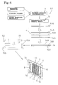
- Fig. 5 is a diagram showing the principle of papermaking
- Fig. 6 is a process view showing the principle of production of the separator
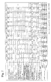
- Figs. 7 and 8 are tables showing data of Examples 1 to 17 and Comparative examples 1 to 3.
- fuel cell separator is abbreviated simply as "separator”.
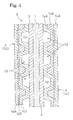
- the solid polymer electrolyte fuel cell E is configured into a stack structure in which plural unit cells 5 each configured by: an electrolyte film 1 which is an ion exchange film formed by, for example, a fluorine resin; an anode 2 and cathode 3 which are formed by carbon cloth woven with carbon fiber threads, carbon paper, or carbon felt, and which sandwich the electrolyte film 1 from the both sides to function as gas diffusion electrodes constituting a sandwich structure; and separators 4, 4 which sandwich the sandwich structure from the both sides are stacked, and current collector plates which are not shown are placed in both ends of the stacked cells.
- an electrolyte film 1 which is an ion exchange film formed by, for example, a fluorine resin
- an anode 2 and cathode 3 which are formed by carbon cloth woven with carbon fiber threads, carbon paper, or carbon felt, and which sandwich the electrolyte film 1 from the both sides to function as gas diffusion electrodes constituting a sandwich structure
- separators 4, 4 which sandwich the
- fuel gas holes 6, 7 containing hydrogen, oxidation gas holes 8, 9 containing oxygen, and cooling water holes 10 are formed.
- the holes 6, 7, 8, 9, 10 of the separators 4 pass through the interior of the fuel cell E in the longitudinal direction to form a fuel gas supply manifold, a fuel gas discharge manifold, an oxidation gas supply manifold, an oxidation gas discharge manifold, and a cooling water path.
- ridges (ribs) 11 are formed in the front and rear sides so that a basic section shape is a rectangular wave shape, and fuel gas flow paths 12 due to butting of the anode 2 and the ridges 11, and oxidation gas flow paths 13 due to butting of the cathode 3 and the ridges 11 are formed.
- the side where the electrolyte film 1 exists is set as the inner side
- the rear side (inner side) portions of the outward ridges 11 in the separators 4 are adjacent to each other, whereby independent cooling water paths 10 can be formed.
- the fuel gas which is supplied from a fuel gas supply apparatus disposed outside to the fuel cell E, and which contains hydrogen is supplied to the fuel gas flow paths 12 of the unit cells 5 through the fuel gas supply manifold to exhibit an electrochemical reaction on the sides of the anodes 2 of the unit cells 5, and, after the reaction, the fuel gas is discharged to the outside through the fuel gas flow paths 12 of the unit cells 5 and the fuel gas discharge manifold.
- the oxidation gas (air) which is supplied from an oxidation gas supply apparatus disposed outside to the fuel cell E, and which contains oxygen is supplied to the oxidation gas flow paths 13 of the unit cells 5 through the oxidation gas supply manifold to exhibit an electrochemical reaction on the sides of the cathodes 3 of the unit cells 5, and, after the reaction, the oxidation gas is discharged to the outside through the oxidation gas flow paths 13 of the unit cells 5 and the oxidation gas discharge manifold.
- an electrochemical reaction in the whole fuel cell E advances to directly convert the chemical energy of the fuel to the electric energy, thereby exerting a predetermined cell performance.
- the fuel cell E is operated in the temperature range of about 80 to 100°C, and hence the operation involves heat generation.
- cooling water is supplied from a cooling water supply apparatus disposed in the outside, to the fuel cell E, and circulated through the cooling water paths, thereby preventing the temperature in the fuel cell E from being raised.
- the cell structure may be that shown in Fig. 4 .
- the cell of Fig. 4 is configured into a structure where, in the surface of each of the separators 4, many dot-like ribs (ribs of a predetermined shape) 11 are arranged vertically and horizontally at regular intervals, vertical and horizontal fuel gas flow paths 12 are formed between the ribs 11 and the surface of the anode 2, and vertical and horizontal oxidation gas flow paths 13 are formed between the ribs 11 and the surface of the cathode 3.
- a second sheet 14B which is an intermediate layer, and which has an excellent moldability flows to a thicker portion to be easily changed to a state where the density is uneven.
- the separator 4 is produced by performing press molding a preform that is formed into a plate-like shape, with using a molding die.
- the production method is configured by: a primary molding step S1 of producing a preform 14 having a plate-like shape which is approximate to the shape of the separator; and a secondary molding step S2 of pressurizing the preform 14 by a molding die 15 to form the separator 4 having the final shape.
- the target characteristics of the separator 4 are as follows: the contact resistance is 30 m ⁇ •cm 2 or less, the bending strength is 25 MPa or more, the bending strain is 0.6 to 2.1%, and the gas permeability coefficient is 1 ⁇ 10 -8 mol•m/m 2 •s•MPa or less.
- the primary molding step S1 is a step of, as shown in Fig. 6 , producing the preform 14 having a sandwich structure where the second sheet 14B in which graphite powder is applied to a thermosetting resin is interposed between a pair of first sheets 14A obtained by a papermaking process using a raw material in which a fibrous filler is added to expanded graphite, and has a papermaking step a, a post-impregnating step b, and a stacking step c.
- the papermaking step a is a step of producing the first sheet 14A by a papermaking process using a raw material in which a fibrous filler is added to expanded graphite, and, as shown in Fig. 6 , performs a papermaking process using a raw material which has expanded graphite (conductive material) that is a main raw material, and a fibrous filler at a predetermined blending ratio, thereby forming the first sheet 14A for the preform 14.
- the original meaning of papermaking is "making paper using a material for paper”.
- the original meaning of papermaking as used in the specification is “making the first sheet using the material for the first sheet”. Next, the papermaking will be described briefly.
- Fig. 5 schematically shows the papermaking step a of producing the first sheet 14A.
- a dispersion solution of graphite (expanded graphite), a fibrous filler, a soft hardening resin, and water is placed in a hopper 20, and supplied dropwise from a lower-end outlet 20a of the hopper 20 to the upper face of a conveyance start end side of an endless rotary strip-like metal gauze 23 which is wound around rollers 21, 22.
- the dispersion solution undergoes a papermaking process (a skimming process) to form an approximately sheet-like member, and the member is lifted up from the conveyance end of the metal gauze 23 to be conveyed along a lifting drum 24 having a large diameter, and then passed between plural upper and lower finishing rollers 25, 26, thereby forming the first sheet 14A (paper-made sheet).
- a papermaking process a skimming process
- the post-impregnating step b is a step of impregnating the first sheet 14A which is paper-made in the papermaking step a, with a phenol resin, thereby producing the first sheet 14A in a state where it becomes a component of the preform 14.
- the stacking step c is a step of interposing and impregnating the second sheet 14B in which a phenol resin (an example of a thermosetting resin) is applied to graphite (graphite powder or the like), between the pair of first sheets 14A produced in the papermaking step a and the post-impregnating step b, thereby producing the preform 14 configured by, as shown in Fig. 6 , a three-layer sandwich structure of the upper and lower first sheets 14A, 14A and the intermediate second sheet 14B.
- the secondary molding step S2 is a step of pressurizing by a press the preform 14 having the three-layer sandwich structure with using the molding die 15 configured by, for example, an upper die 15a and a lower die 15b, thereby producing the separator 4 having the predetermined final shape.
- the molding die 15 configured by, for example, an upper die 15a and a lower die 15b
- the papermaking step a in the primary molding step S1 is performed in the following manner.
- a fibrous filler in which 3% of carbon fibers, 7% of acrylic fibers, 1% of PET fibers, and 1% of aramid fibers are blended is defiberized with using a domestic mixer to be adjusted so as to have a predetermined pulp density (for example, 1%).
- a predetermined pulp density for example, 1%
- 83% of expanded graphite of, for example, 40 ⁇ m is added, and water is further added to readjust the slurry to the solid content concentration of 0.1%.
- a sheet-like member which is produced in the papermaking step a is processed by a standard square sheet machine, thereby obtaining the first sheet 14A at a basis weight of 70 g/m 2 and having a 25 cm square shape.
- impregnation is performed with using a phenol resin solution to obtain the first sheet 14A for the preform 14.
- the impregnation amount of the phenol resin in Example 1 is set so that the blending ratio after impregnation is 5%.
- the first sheet 14A produced by the papermaking process is slightly inferior in moldability, for example, hardly bendable, but has excellent mechanical and electrical characteristics.
- a second-sheet forming step in the primary molding step S1 is a step of coating graphite powder (preferably, having a particle diameter of about 1 to 200 ⁇ m) with a phenol resin to produce the second sheet 14B which is resin carbon.
- the second sheet 14B which is resin carbon is inferior in mechanical characteristics, but excellent in moldability.
- the second sheet 14B may be produced in the following manner.
- the sheet is configured by a thin plate-like molded member in which a carbon-phenol resin molding compound that is prepared by mixing and reacting phenols, aldehydes, and carbon in the presence of a catalyst is molded.
- the carbon-phenol resin molding compound is obtained as a material in which carbon is thinly and uniformly covered with the phenol resin, by reacting phenols and aldehydes with carbon in the presence of a catalyst while being mixed with carbon.
- the preform 14 having the three-layer sandwich structure which is produced in the primary molding step S1 is subjected to heat and pressure molding during five minutes at a surface pressure of 20 MPa with using a molding die of 170°C (see Fig. 6 ), to obtain the separator 4.
- the characteristics of the separator 4 in this case were as follows: the contact resistance is 10 m ⁇ • cm 2 , the gas permeability coefficient is 4 ⁇ 10 -11 mol•m/m 2 •s•MPa, the bending strength is 50 MPa, the bending strain is 2%, and the thickness is 0.15 mm.
- Figs. 7 and 8 show a physical property and characteristic table ( Fig. 7 ) of Examples 1 to 10 of the separator 4 of the invention and Comparative examples 1 to 3, and physical properties and characteristics ( Fig. 8 ) of Examples 11 to 17.
- the data of the first sheets 14A are different, and those of the second sheet 14B are identical with one another.
- the contact resistance is tested in the following manner. First, two test pieces are sandwiched between two flat copper plates, and a voltage under a pressure of 1 Mpa is measured as a voltage A. Then, four test pieces are used, and a voltage B is measured in a similar manner as described above. The difference between the voltages A and B is divided by 2, and further divided by the area of the test pieces, thereby obtaining the contact resistance (unit: m ⁇ •cm 2 ) .
- the bending strength and the bending strain are measured by the three-point bending test.
- the measurement was conducted while setting the distance between fulcrums to 7.8 mm, the cross-head speed to 10 mm/min., and the width of the test pieces to 15 mm.
- the gas permeability coefficient was measured in accordance with JIS K7126A method (differential pressure method) with using a gas permeability measuring device (BT-1 manufactured by Toyo Seiki Seisaku-sho, Ltd).
- Examples 1 to 6 show data in the case where the blending ratio of the phenol resin in the post-impregnating step b was changed in the step of 5% in a range of 5 to 30%
- Example 7 shows data in the case where, in place of the post-impregnation of the phenol resin, the phenol resin and natural graphite were post-impregnated
- Example 8 shows data in the case where, in place of the post-impregnation of the phenol resin, graphite covered with a phenol resin was post-impregnated.
- Example 9 shows data in the case where the post-impregnation of the phenol resin was set to 13%, and the internal adding of the phenol resin (the internal adding means "7% of phenol resin is blended as a raw material of the papermaking step a") was set to 7%.
- Example 10 shows data in the case where graphite was applied to the surface of the preform 14, i.e., the surface sides of the first sheets 14A, 14A in the both ends which were post-impregnated with the phenol resin.
- Example 10 namely, an applying step of applying graphite to the surface of the first sheet 14A which is impregnated with the phenol resin in the post-impregnating step b was added.
- the blending ratios (blending amounts) of the carbon fibers, acrylic fibers, PET fibers, and aramid fibers which constitute the fibrous filler are identical.
- Examples 11 to 17 show data in the case where the blending ratio of the expanded graphite was changed in the step of 5% in a range of 60 to 90%.
- the blending ratio of the phenol resin which is post-impregnated is set to 20% in a similar manner as Example 4.
- Comparative examples 1 and 2 show data in the case where a separator 4 of the totally paper-made type which is configured by stacking three first sheets 14A according to Examples 4 and 5, and which does not have the second sheet 14B is set.
- Comparative example 3 shows data in the case where a separator 4 of the whole resin carbon type which is configured by stacking three second sheets 14B, and which does not have the first sheet 14A is set.
- Comparative examples 1 and 2 of the totally paper-made type the characteristics are excellent, but the contact resistance and the gas permeability coefficient depart from the specified values, many edges are broken, and the moldability is poor, with the result that the comparative examples are not acceptable.
- Comparative example 3 of the whole resin carbon type the bending strain is outside the range, and edge breakage is observed, with the result that also the comparative example is not acceptable.
- the blending ratio material ratio
- the impregnation ratio of the phenol resin is set to a range of 20 to 30%, a super high-strength separator in which the bending strength is 80 MPa or more can be produced.
- the impregnation ratio of the phenol resin is set to a range of 20 to 30% and the blending ratio (material ratio) of the expanded graphite is set to a range of 60 to 70%, there is an advantage that an ultra high-strength fuel cell separator in which the bending strength is 105 MPa or more can be realized.
- Embodiment 1 of the invention is a separator which is to be produced by performing press molding on a preform 14 that is formed into a plate-like shape, with a molding die, wherein the preform is configured into a sandwich structure where the second sheet in which a thermosetting resin is applied to graphite is interposed between the pair of first sheets obtained by the papermaking process using a raw material in which a fibrous filler is added to expanded graphite.
- the fuel cell separator to be produced by performing press molding on a preform in which expanded graphite is used as the main raw material is improved so that the preform has the sandwich structure where the second sheet made of resin carbon is sandwiched between the two first sheets produced by a papermaking process, and therefore it is possible to provide a fuel cell separator in which the characteristics of the mechanical strength, the flexibility, and the gas impermeability are improved, and a light and compact configuration that is preferred in the automobile use or the like can be realized.
- the separator has the sandwich structure where the second sheet 14B which is excellent in moldability is interposed between the pair of first sheets 14A which are excellent in mechanical strength and electrical characteristics.
- the moldability is improved while the sealing property (gas permeability coefficient) is further improved, with the result that a fuel cell separator having excellent total performance, and a method of producing the fuel cell separator can be realized.
Landscapes
- Engineering & Computer Science (AREA)
- Chemical & Material Sciences (AREA)
- Life Sciences & Earth Sciences (AREA)
- Manufacturing & Machinery (AREA)
- Sustainable Development (AREA)
- Sustainable Energy (AREA)
- Chemical Kinetics & Catalysis (AREA)
- Electrochemistry (AREA)
- General Chemical & Material Sciences (AREA)
- Mechanical Engineering (AREA)
- Composite Materials (AREA)
- Fuel Cell (AREA)
Applications Claiming Priority (2)
| Application Number | Priority Date | Filing Date | Title |
|---|---|---|---|
| JP2006104424A JP4580889B2 (ja) | 2006-04-05 | 2006-04-05 | 燃料電池用セパレータ及びその製造方法 |
| PCT/JP2007/000359 WO2007125640A1 (fr) | 2006-04-05 | 2007-04-03 | Separateur pour pile a combustible et son procede de production |
Publications (1)
| Publication Number | Publication Date |
|---|---|
| EP2017912A1 true EP2017912A1 (fr) | 2009-01-21 |
Family
ID=38655181
Family Applications (1)
| Application Number | Title | Priority Date | Filing Date |
|---|---|---|---|
| EP07737016A Withdrawn EP2017912A1 (fr) | 2006-04-05 | 2007-04-03 | Séparateur pour pile à combustible et son procédé de production |
Country Status (6)
| Country | Link |
|---|---|
| US (1) | US20100159357A1 (fr) |
| EP (1) | EP2017912A1 (fr) |
| JP (1) | JP4580889B2 (fr) |
| KR (1) | KR20080109848A (fr) |
| CN (1) | CN101411020A (fr) |
| WO (1) | WO2007125640A1 (fr) |
Cited By (2)
| Publication number | Priority date | Publication date | Assignee | Title |
|---|---|---|---|---|
| CN105680074A (zh) * | 2016-03-22 | 2016-06-15 | 江苏神州碳制品有限公司 | 一种浸渍石墨双极板的制作工艺 |
| EP2415580A4 (fr) * | 2009-03-30 | 2016-07-27 | Showa Denko Kk | Procédé de moulage à la presse de feuilles et procédé de fabrication d'un séparateur pour pile à combustible |
Families Citing this family (22)
| Publication number | Priority date | Publication date | Assignee | Title |
|---|---|---|---|---|
| JP2008123971A (ja) * | 2006-11-16 | 2008-05-29 | Tokai Carbon Co Ltd | 固体高分子形燃料電池セパレータ材の製造方法 |
| JP4792448B2 (ja) * | 2007-10-10 | 2011-10-12 | 日本ピラー工業株式会社 | 燃料電池セパレータ及びその製造方法 |
| JP4792446B2 (ja) * | 2007-10-10 | 2011-10-12 | 日本ピラー工業株式会社 | 燃料電池セパレータ |
| JP4792445B2 (ja) * | 2007-10-10 | 2011-10-12 | 日本ピラー工業株式会社 | 燃料電池セパレータ |
| JP2010123360A (ja) * | 2008-11-19 | 2010-06-03 | Nippon Pillar Packing Co Ltd | 燃料電池セパレータ及びその製造方法 |
| KR101173059B1 (ko) | 2010-09-29 | 2012-08-13 | 한국과학기술원 | 고분자 전해질 연료전지용 복합재료 분리판 및 이의 제조방법 |
| CN102585259B (zh) * | 2012-01-20 | 2013-10-09 | 苏州大学 | 一种膨胀石墨薄片/热固性树脂复合材料的制备方法 |
| US9963395B2 (en) | 2013-12-11 | 2018-05-08 | Baker Hughes, A Ge Company, Llc | Methods of making carbon composites |
| US9325012B1 (en) * | 2014-09-17 | 2016-04-26 | Baker Hughes Incorporated | Carbon composites |
| US10315922B2 (en) | 2014-09-29 | 2019-06-11 | Baker Hughes, A Ge Company, Llc | Carbon composites and methods of manufacture |
| US10480288B2 (en) | 2014-10-15 | 2019-11-19 | Baker Hughes, A Ge Company, Llc | Articles containing carbon composites and methods of manufacture |
| US9962903B2 (en) | 2014-11-13 | 2018-05-08 | Baker Hughes, A Ge Company, Llc | Reinforced composites, methods of manufacture, and articles therefrom |
| US9745451B2 (en) | 2014-11-17 | 2017-08-29 | Baker Hughes Incorporated | Swellable compositions, articles formed therefrom, and methods of manufacture thereof |
| US11097511B2 (en) | 2014-11-18 | 2021-08-24 | Baker Hughes, A Ge Company, Llc | Methods of forming polymer coatings on metallic substrates |
| US10300627B2 (en) | 2014-11-25 | 2019-05-28 | Baker Hughes, A Ge Company, Llc | Method of forming a flexible carbon composite self-lubricating seal |
| KR101806641B1 (ko) | 2015-12-16 | 2017-12-08 | 현대자동차주식회사 | 연료전지의 단위 셀 사출금형 |
| US10125274B2 (en) | 2016-05-03 | 2018-11-13 | Baker Hughes, A Ge Company, Llc | Coatings containing carbon composite fillers and methods of manufacture |
| US10344559B2 (en) | 2016-05-26 | 2019-07-09 | Baker Hughes, A Ge Company, Llc | High temperature high pressure seal for downhole chemical injection applications |
| WO2019106766A1 (fr) * | 2017-11-29 | 2019-06-06 | 日産自動車株式会社 | Empilement de piles à combustible |
| WO2019174029A1 (fr) * | 2018-03-16 | 2019-09-19 | 清华大学 | Plaque bipolaire composite pour pile à combustible et champ d'écoulement tridimensionnel à double canal associé |
| JP7093713B2 (ja) * | 2018-10-23 | 2022-06-30 | 信越ポリマー株式会社 | 燃料電池用セパレータ及びその製造方法 |
| JP7056796B1 (ja) | 2021-12-20 | 2022-04-19 | 日清紡ケミカル株式会社 | 燃料電池セパレータ用前駆体シートおよび燃料電池セパレータ |
Family Cites Families (8)
| Publication number | Priority date | Publication date | Assignee | Title |
|---|---|---|---|---|
| JPS63270138A (ja) * | 1987-04-30 | 1988-11-08 | Kobe Steel Ltd | 複合炭素部材及びその製造方法 |
| JP3330343B2 (ja) * | 1999-02-09 | 2002-09-30 | 日本ピラー工業株式会社 | 燃料電池用セパレータ |
| JP4441950B2 (ja) * | 1999-06-29 | 2010-03-31 | Dic株式会社 | 燃料電池用セパレータの製造方法 |
| JP2002093431A (ja) * | 2000-09-11 | 2002-03-29 | Toyo Tanso Kk | 燃料電池用セパレータ |
| JP2003172776A (ja) * | 2001-12-10 | 2003-06-20 | Fujitsu Ten Ltd | レーダ装置 |
| JP2004216756A (ja) * | 2003-01-16 | 2004-08-05 | Sumitomo Bakelite Co Ltd | 予備成形体成形金型及び予備成形体を用いた燃料電池セパレーターの製造方法 |
| JP2006164816A (ja) * | 2004-12-09 | 2006-06-22 | Jfe Chemical Corp | 抄造シート及び燃料電池用セパレータ |
| JP4650673B2 (ja) * | 2004-12-14 | 2011-03-16 | 東海カーボン株式会社 | 燃料電池用セパレータ材とその製造方法 |
-
2006
- 2006-04-05 JP JP2006104424A patent/JP4580889B2/ja not_active Expired - Fee Related
-
2007
- 2007-04-03 KR KR1020087025128A patent/KR20080109848A/ko not_active Ceased
- 2007-04-03 CN CNA2007800115249A patent/CN101411020A/zh active Pending
- 2007-04-03 US US12/225,368 patent/US20100159357A1/en not_active Abandoned
- 2007-04-03 EP EP07737016A patent/EP2017912A1/fr not_active Withdrawn
- 2007-04-03 WO PCT/JP2007/000359 patent/WO2007125640A1/fr not_active Ceased
Cited By (3)
| Publication number | Priority date | Publication date | Assignee | Title |
|---|---|---|---|---|
| EP2415580A4 (fr) * | 2009-03-30 | 2016-07-27 | Showa Denko Kk | Procédé de moulage à la presse de feuilles et procédé de fabrication d'un séparateur pour pile à combustible |
| US9789634B2 (en) | 2009-03-30 | 2017-10-17 | Showa Denko K.K. | Sheet press molding method and method of manufacturing fuel cell separator |
| CN105680074A (zh) * | 2016-03-22 | 2016-06-15 | 江苏神州碳制品有限公司 | 一种浸渍石墨双极板的制作工艺 |
Also Published As
| Publication number | Publication date |
|---|---|
| CN101411020A (zh) | 2009-04-15 |
| JP2007280725A (ja) | 2007-10-25 |
| WO2007125640A1 (fr) | 2007-11-08 |
| KR20080109848A (ko) | 2008-12-17 |
| US20100159357A1 (en) | 2010-06-24 |
| JP4580889B2 (ja) | 2010-11-17 |
Similar Documents
| Publication | Publication Date | Title |
|---|---|---|
| EP2017912A1 (fr) | Séparateur pour pile à combustible et son procédé de production | |
| EP2034545A1 (fr) | Séparateur pour pile à combustible et son processus de fabrication | |
| CN102257661B (zh) | 气体扩散层及其制造方法以及燃料电池 | |
| EP3229299B1 (fr) | Feuille de carbone, matériau de base d'électrode de diffusion de gaz, et pile à combustible | |
| EP1116293B1 (fr) | Plaque de transport d'eau | |
| US7049025B2 (en) | Gas diffusion substrate | |
| US6187466B1 (en) | Fuel cell with water capillary edge seal | |
| EP1788651B1 (fr) | Matériau poreux de base d"électrode et procédé pour la fabrication de celui-ci | |
| CN101068953B (zh) | 用在pem燃料电池中的扩散介质 | |
| EP3326985B1 (fr) | Feuille de carbone, substrat d'électrode à diffusion gazeuse, corps cylindrique et pile à combustible | |
| CN1934734A (zh) | 膜电极组件、其制造方法以及高分子电解质燃料电池 | |
| CN117043409B (zh) | 碳片材和其制造方法、气体扩散电极以及燃料电池 | |
| KR102050971B1 (ko) | 초경량 탄소계 분리판 및 그를 포함하는 연료전지 스택과 그 제조방법 | |
| JP4792445B2 (ja) | 燃料電池セパレータ | |
| JP2005100748A (ja) | 電解質膜電極接合体及びその製造方法並びに固体高分子型燃料電池 | |
| JP2007188696A (ja) | 燃料電池用セパレータ及びその製造方法 | |
| KR20090126979A (ko) | 연료전지의 엔드플레이트 및 그 제조방법 | |
| JP4508574B2 (ja) | 燃料電池用セパレータ、燃料電池用セパレータの製造方法 | |
| KR20170068686A (ko) | 복합재 분리판 및 그 제조 방법 | |
| EP4683007A1 (fr) | Feuille de fibre de carbone, couche de diffusion de gaz pour pile à combustible, et composite d'électrode à membrane | |
| JP2011222329A (ja) | 燃料電池セパレータ及びその製造方法 |
Legal Events
| Date | Code | Title | Description |
|---|---|---|---|
| PUAI | Public reference made under article 153(3) epc to a published international application that has entered the european phase |
Free format text: ORIGINAL CODE: 0009012 |
|
| 17P | Request for examination filed |
Effective date: 20081105 |
|
| AK | Designated contracting states |
Kind code of ref document: A1 Designated state(s): AT BE BG CH CY CZ DE DK EE ES FI FR GB GR HU IE IS IT LI LT LU LV MC MT NL PL PT RO SE SI SK TR |
|
| AX | Request for extension of the european patent |
Extension state: AL BA HR MK RS |
|
| STAA | Information on the status of an ep patent application or granted ep patent |
Free format text: STATUS: THE APPLICATION IS DEEMED TO BE WITHDRAWN |
|
| 18D | Application deemed to be withdrawn |
Effective date: 20101103 |