EP2018303B1 - Dispositif de freinage hydraulique - Google Patents
Dispositif de freinage hydraulique Download PDFInfo
- Publication number
- EP2018303B1 EP2018303B1 EP07727124A EP07727124A EP2018303B1 EP 2018303 B1 EP2018303 B1 EP 2018303B1 EP 07727124 A EP07727124 A EP 07727124A EP 07727124 A EP07727124 A EP 07727124A EP 2018303 B1 EP2018303 B1 EP 2018303B1
- Authority
- EP
- European Patent Office
- Prior art keywords
- channel
- hydraulic
- installation space
- brake system
- valve
- Prior art date
- Legal status (The legal status is an assumption and is not a legal conclusion. Google has not performed a legal analysis and makes no representation as to the accuracy of the status listed.)
- Active
Links
Images

Classifications
-
- B—PERFORMING OPERATIONS; TRANSPORTING
- B60—VEHICLES IN GENERAL
- B60T—VEHICLE BRAKE CONTROL SYSTEMS OR PARTS THEREOF; BRAKE CONTROL SYSTEMS OR PARTS THEREOF, IN GENERAL; ARRANGEMENT OF BRAKING ELEMENTS ON VEHICLES IN GENERAL; PORTABLE DEVICES FOR PREVENTING UNWANTED MOVEMENT OF VEHICLES; VEHICLE MODIFICATIONS TO FACILITATE COOLING OF BRAKES
- B60T8/00—Arrangements for adjusting wheel-braking force to meet varying vehicular or ground-surface conditions, e.g. limiting or varying distribution of braking force
- B60T8/32—Arrangements for adjusting wheel-braking force to meet varying vehicular or ground-surface conditions, e.g. limiting or varying distribution of braking force responsive to a speed condition, e.g. acceleration or deceleration
- B60T8/34—Arrangements for adjusting wheel-braking force to meet varying vehicular or ground-surface conditions, e.g. limiting or varying distribution of braking force responsive to a speed condition, e.g. acceleration or deceleration having a fluid pressure regulator responsive to a speed condition
- B60T8/36—Arrangements for adjusting wheel-braking force to meet varying vehicular or ground-surface conditions, e.g. limiting or varying distribution of braking force responsive to a speed condition, e.g. acceleration or deceleration having a fluid pressure regulator responsive to a speed condition including a pilot valve responding to an electromagnetic force
-
- B—PERFORMING OPERATIONS; TRANSPORTING
- B60—VEHICLES IN GENERAL
- B60T—VEHICLE BRAKE CONTROL SYSTEMS OR PARTS THEREOF; BRAKE CONTROL SYSTEMS OR PARTS THEREOF, IN GENERAL; ARRANGEMENT OF BRAKING ELEMENTS ON VEHICLES IN GENERAL; PORTABLE DEVICES FOR PREVENTING UNWANTED MOVEMENT OF VEHICLES; VEHICLE MODIFICATIONS TO FACILITATE COOLING OF BRAKES
- B60T8/00—Arrangements for adjusting wheel-braking force to meet varying vehicular or ground-surface conditions, e.g. limiting or varying distribution of braking force
- B60T8/32—Arrangements for adjusting wheel-braking force to meet varying vehicular or ground-surface conditions, e.g. limiting or varying distribution of braking force responsive to a speed condition, e.g. acceleration or deceleration
- B60T8/34—Arrangements for adjusting wheel-braking force to meet varying vehicular or ground-surface conditions, e.g. limiting or varying distribution of braking force responsive to a speed condition, e.g. acceleration or deceleration having a fluid pressure regulator responsive to a speed condition
- B60T8/36—Arrangements for adjusting wheel-braking force to meet varying vehicular or ground-surface conditions, e.g. limiting or varying distribution of braking force responsive to a speed condition, e.g. acceleration or deceleration having a fluid pressure regulator responsive to a speed condition including a pilot valve responding to an electromagnetic force
- B60T8/3615—Electromagnetic valves specially adapted for anti-lock brake and traction control systems
- B60T8/3675—Electromagnetic valves specially adapted for anti-lock brake and traction control systems integrated in modulator units
- B60T8/368—Electromagnetic valves specially adapted for anti-lock brake and traction control systems integrated in modulator units combined with other mechanical components, e.g. pump units, master cylinders
-
- B—PERFORMING OPERATIONS; TRANSPORTING
- B60—VEHICLES IN GENERAL
- B60T—VEHICLE BRAKE CONTROL SYSTEMS OR PARTS THEREOF; BRAKE CONTROL SYSTEMS OR PARTS THEREOF, IN GENERAL; ARRANGEMENT OF BRAKING ELEMENTS ON VEHICLES IN GENERAL; PORTABLE DEVICES FOR PREVENTING UNWANTED MOVEMENT OF VEHICLES; VEHICLE MODIFICATIONS TO FACILITATE COOLING OF BRAKES
- B60T8/00—Arrangements for adjusting wheel-braking force to meet varying vehicular or ground-surface conditions, e.g. limiting or varying distribution of braking force
-
- B—PERFORMING OPERATIONS; TRANSPORTING
- B60—VEHICLES IN GENERAL
- B60T—VEHICLE BRAKE CONTROL SYSTEMS OR PARTS THEREOF; BRAKE CONTROL SYSTEMS OR PARTS THEREOF, IN GENERAL; ARRANGEMENT OF BRAKING ELEMENTS ON VEHICLES IN GENERAL; PORTABLE DEVICES FOR PREVENTING UNWANTED MOVEMENT OF VEHICLES; VEHICLE MODIFICATIONS TO FACILITATE COOLING OF BRAKES
- B60T8/00—Arrangements for adjusting wheel-braking force to meet varying vehicular or ground-surface conditions, e.g. limiting or varying distribution of braking force
- B60T8/32—Arrangements for adjusting wheel-braking force to meet varying vehicular or ground-surface conditions, e.g. limiting or varying distribution of braking force responsive to a speed condition, e.g. acceleration or deceleration
- B60T8/34—Arrangements for adjusting wheel-braking force to meet varying vehicular or ground-surface conditions, e.g. limiting or varying distribution of braking force responsive to a speed condition, e.g. acceleration or deceleration having a fluid pressure regulator responsive to a speed condition
- B60T8/48—Arrangements for adjusting wheel-braking force to meet varying vehicular or ground-surface conditions, e.g. limiting or varying distribution of braking force responsive to a speed condition, e.g. acceleration or deceleration having a fluid pressure regulator responsive to a speed condition connecting the brake actuator to an alternative or additional source of fluid pressure, e.g. traction control systems
- B60T8/4809—Traction control, stability control, using both the wheel brakes and other automatic braking systems
- B60T8/4827—Traction control, stability control, using both the wheel brakes and other automatic braking systems in hydraulic brake systems
- B60T8/4863—Traction control, stability control, using both the wheel brakes and other automatic braking systems in hydraulic brake systems closed systems
- B60T8/4872—Traction control, stability control, using both the wheel brakes and other automatic braking systems in hydraulic brake systems closed systems pump-back systems
Definitions
- the invention relates to a hydraulic brake system with a device for controlling the brake slip, the drive slip and / or the driving stability of a vehicle equipped with this hydraulic brake system.
- brake systems are well known on the market under the terms brake systems with anti-lock control (ABS), traction control (ASR) or with electronic stability program (ESP).
- ABS anti-lock control
- ASR traction control
- ESP electronic stability program
- the heart of such brake systems forms a switched between a master cylinder and the wheel brake hydraulic unit with a hydraulic block to which for brake pressure control various hydraulic components, such as pumps, valves and / or memory, are arranged.
- a corresponding hydraulic block with a grown electronic control unit for on-demand actuation of the valves and an electric motor for driving the pump is for example from DE 44 31 250 A1 already known.
- this known hydraulic block has installation spaces which communicate with one another according to a hydraulic circuit diagram on which the vehicle brake system is based.
- This hydraulic circuit diagram is mechanically implemented by means of channels which pass through the hydraulic block.
- a possible mechanical implementation of a hydraulic circuit diagram can be inferred in particular from FIG. 5 of the above-mentioned published patent application.
- An article with the features of claim 1 has the advantage that the hydraulic block used occupies very little space and is particularly easy to machine. Due to its compactness, the hydraulic block also has a low weight.
- These advantages are based inter alia on an arrangement according to the invention or a guidance according to the invention of the channels in the hydraulic block.
- the proposed channel guide is made possible by a multifunctional closure element which, in addition to its closure function, serves the purpose of blocking a channel connection, which makes sense only from a manufacturing point of view, but is not provided in the hydraulic circuit diagram. Said channel connection connects the installation spaces of two not communicating with each other in the hydraulic circuit diagram valves.
- Claim 2 defines those valves on their function within the hydraulic vehicle brake system, the installation spaces are particularly suitable for the interconnection of the invention.
- the two valves can now be arranged in parallel and without height offset to each other in a row on the hydraulic block. This is a factor in the low volume of the hydraulic block.
- a closure element can preferably be used as a commodity on the market available pin with a cylindrical cross-section, which, for example, in the mentioned, formed as a bore channel is einpressbar (claims 7 and 8).
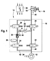
- FIG. 1 shows a necessary for the understanding of the invention part of the hydraulic circuit diagram of a hydraulic brake system.
- FIG. 2 represents in a perspective view of the hydraulic block of such a brake system.
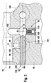
- FIG. 3 nor the actual core of the invention illustrated by a longitudinal section through the relevant part of the hydraulic block.
- FIG. 1 a part of the hydraulic circuit diagram of a hydraulic vehicle brake system.
- This hydraulic circuit diagram comprises a master cylinder 10 for acting on a wheel brake 12 with brake pressure, and a device connected between the master cylinder 10 and the wheel brake 12 for regulating this brake pressure 14 as a function of the wheel slip at an associated wheel of the vehicle.
- the device for controlling the brake pressure 14 with its various hydraulic components has a hydraulic block 16 which in FIG. 1 symbolically represented by a dashed line.
- the individual components of the device 14 is a total of four electromagnetically controllable valves 20 to 26, a memory 28, a mechanically operating check valve 30, a pump 32 and pressure-carrying, connecting these components to a hydraulic circuit lines 40 to 46th
- a first line 40 extends from the master cylinder 10 to the wheel brake 12.
- a so-called changeover valve 20 is arranged as the first valve downstream of the master cylinder 10.
- This switching valve 20 assumes a through position in its basic position and can be switched by electrical control in a blocking position. In the activated state, the pressure medium connection from the master cylinder 10 to the wheel brake 12 is interrupted. Further downstream of the switching valve 20 is another normally open valve, hereinafter referred to as the inlet valve 22 is designated.
- the inlet valve 22 is connected directly to the wheel brake 12 and can be switched electromagnetically into a blocking position.
- a second line 42 (return), in which a normally closed outlet valve 24 is arranged.
- This outlet valve 24 controls a connecting line 44 from the wheel brake 12 to the inlet of the pump 32, between the outlet valve 24 and the pump 32 still a memory 28 and, downstream of the memory 28, a direction of the pump 32 opening check valve 30 are arranged.
- the check valve 30 ensures that pressure fluid can only flow from the reservoir 28 to the pump 32, but not back.
- a fourth valve which is referred to as high-pressure switching valve 26.
- This high-pressure switching valve 26 is closed in its basic position and, in the case of its actuation, makes it possible to supply the pump 32 with pressure medium from the master cylinder 10 if necessary.
- the pressure side of the pump 32 opens between the switching valve 20 and the inlet valve 22 in the first line 40 from the master cylinder 10 to the wheel brake 12 a.
- the first line 40 from the master cylinder 10 to the wheel brake 12 is open, the switching valve 20 and the inlet valve 22 assume their normal position.
- brake pressure can be built up in the wheel brake 12.
- the control valve 20 is actuated, which then interrupts the connection of the master brake cylinder 10 to the wheel brake 12.
- the pump 32 starts, the inlet valve 22 is closed and the outlet valve 24 is opened.
- the pump 32 can thereby suck pressure medium from the wheel brake 12 and initiate a reduction of the brake pressure in the wheel brake 12.
- the brake pressure at the wheel brake 12 can be rebuilt.
- the pump 32 conveys the pressure medium between the changeover valve 20 and the inlet valve 22 back to the first line 40.
- the memory 28 holds pressure medium and ensures start-up of the pump 32.
- the high-pressure switching valve 26 can be opened electromagnetically, so that the pump 32 can suck additional pressure medium from the master cylinder 10 and convey it to the inlet valve 22.
- the check valve 30, which can only be flowed through in one direction, ensures that no pressure medium coming from the master cylinder 10 reaches the wheel brake 12 through a possibly still open outlet valve 24.
- the main brake cylinder 10 can be disconnected from the wheel brake 12 by closing the switching valve 20.
- the switching valve 20 With a simultaneous start of the pump 32 can independently of the driver pressure medium via the open inlet valve 22 is promoted to the wheel brake 12 and there a brake pressure to be built up. In other words, the affected driven wheel can be selectively decelerated and thus eliminate the drive slip.
- the vehicle may be braked to stabilize the vehicle. Rad slip occurring for detection, the individual wheels with vehicle-side speed measuring sensors 34 are equipped. An evaluation of the signals supplied by these sensors 34 takes place in the electronic control unit 36. This control unit further processes the incoming signals into control signals for the illustrated valves 20 to 26.
- FIG. 2 shows a three-dimensional view of the hydraulic block 16 in the installed position.
- This hydraulic block 16 has a plurality of in FIG. 1 illustrated hydraulic circuits. It consists of a cuboid metal part 50, in which by means of exciting machining processes, among other installation spaces 52 to 58 are formed for the various valves 20 to 26. In each case four installation spaces 52 to 58 are arranged parallel to one another in three rows 62 - 66, which extend at different heights of the front side of the hydraulic block 50.
- the upper row 62 of installation spaces 52 is for receiving the outlet valves 24 of the hydraulic circuits determined
- the middle row 64 receives the inlet valves 22 of the hydraulic circuits
- in the lower row 66 are the outer installation spaces 56 for receiving the changeover valves 20 and the inner housings 58 for receiving the high-pressure switching valves 26.
- the lower row 66th the installation spaces 56, 58 is further spaced from the middle row 64 than the middle row 64 from the upper row 62. This provides space in the hydraulic block 50 to provide installation spaces 70 for the pumps 32.
- These installation spaces 70 are at right angles to the Installation spaces 52 to 58 of the valves 20 to 26 and start from the side surfaces 72 of the hydraulic block 16.
- FIG. 2 shows only the installation space 70 of a single pump 32, the opposite installation space of a second pump can not be seen in this view.
- the enumerated installation spaces 52 to 58, 70, 74 are connected by pressure-carrying channels with each other to the hydraulic circuits.
- the channels are machined into the hydraulic block 16 by bores 80.
- Four of these pressure-carrying bores 80 start at the FIG. 2 visible side surface 72 of the hydraulic block 16.
- a further bore 82 in the hydraulic block 16 is arranged between the two upper rows 62 and 64 of installation spaces 52, 54. It passes from the front of the hydraulic block 16 to the back and serves to carry out electrical lines, which contacts a fastened on the opposite rear electric motor with the attachable on the visible front electronic control unit 36.
- the drive of a preferably used eccentric which is installed in the interior of the hydraulic block 16 from the back forth. This in FIG. 2 Unrecognizable eccentric forces the pumps 32 to reciprocate lifting motion.
- FIG. 3 shows a section of the hydraulic block 16 in longitudinal section. It can be seen a first channel 90, which is designed in the form of a blind hole and the at an in FIG. 3 left outside of the hydraulic block 16 begins.
- This first channel 90 is arranged below an installation space 70 for a pump 32.
- Its longitudinal axis 92 extends parallel to the longitudinal axis 94 of this installation space 70.
- a second channel 96 extends perpendicular to Longitudinal axis of the installation space 70. This second channel 96 establishes a connection between the pressure side of the pump 32 and the first channel 90.
- the first installation space 98 for the valve 20 is located in the area of the opening point of the second channel 96 in the first channel 90.
- This installation space 98 is only indicated by a dashed line because its cross section extends from the rear side of the hydraulic block 16.
- This installation space 98 is provided for receiving the switching valve 20 and is also contacted with the first channel 90.
- a second installation space 100 is offset parallel and arranged at the same height to the first installation space 98 further inside the hydraulic block 16.
- This installation space 100 receives the high-pressure switching valve 26 and is also hydraulically connected to the first channel 90. Between two installation spaces 98 and 100 of the valves 20, 26, a third, parallel to the second channel 96 extending channel 102 is located.
- This third channel 102 opens at its one end in an installation space 104 for the memory 28 and is opposite to a suction-side region of the installation space 70 of the pump 32 is connected.
- the third channel 102 crosses the first channel 90.
- the check valve 30 Shortly before the installation space of the memory 28 is in the bore 102, the check valve 30. This only allows a flow of pressure medium from the memory 28 out into the first channel 90 and locks the opposite direction.
- the check valve 30 has a valve seat body 106 with a valve seat 108 formed thereon.
- the valve seat 108 cooperates with a closing body 110, which is pressed by a pressure spring 112 against the valve seat 108 for this purpose. This compression spring 112 is clamped between the valve seat body 106 and the closing body 110.
- a closure element 120 here executed for example in the form of a cylindrical pin, pressed.
- This cylindrical pin extends from the outside of the hydraulic block 16 to beyond the discharge point of the second channel 96 in the first channel 90 and to over the mouth of the installation space 98 in the first channel 90 also.
- the closure member 120 has a first outer seal portion 122 facing the outside of the hydraulic block 16. This has the function of closing the first channel 90 to the atmosphere.
- the outer sealing portion 122 is opposed by a second inner sealing portion 124. This blocks a pressure medium connection not required in the hydraulic circuit diagram from the installation space 70 of the pump 32 or from the installation space 98 of the first valve 20 to the installation space of the high-pressure switching valve 26.
- the second channel 96 running from one pressure-side part of the installation space 70 of the pump 32 to the first channel 90, and the installation space 98 of the first valve 20 are hydraulically connected to each other. This is achieved by flow cross sections, which are dimensioned larger than the cross section of the first channel 90.
- the pegs penetrating through the cylindrical pin thus has a between its two sealing portions 122, 124 and flow around the pressure medium center portion 126.
Landscapes
- Physics & Mathematics (AREA)
- Engineering & Computer Science (AREA)
- Fluid Mechanics (AREA)
- Transportation (AREA)
- Mechanical Engineering (AREA)
- Electromagnetism (AREA)
- Regulating Braking Force (AREA)
- Valves And Accessory Devices For Braking Systems (AREA)
Claims (8)
- Système de freinage hydraulique avec un dispositif (14) pour la régulation du glissement de freinage, du glissement d'entraînement et/ou de la stabilité de conduite d'un véhicule, avec un bloc hydraulique (16), qui présente des espaces de montage (52 à 58, 70, 74, 98, 100) pour des composants hydrauliques comme des pompes (32), des soupapes (20 à 26), et/ou des accumulateurs (28), qui peut être amené en contact avec des dispositifs externes comme un cylindre de freinage principal (10) ou des cylindres de frein de roue (12), et qui présente des canaux de fluide de pression, qui mettent en contact les composants en fonction d'un branchement hydraulique à la base du système de freinage du véhicule,
caractérisé par
un premier canal (90) qui relie un premier espace de montage (98) d'une première soupape (20) à un deuxième espace de montage (100) d'une deuxième soupape (26), et qui débouche au niveau d'une face extérieure du bloc hydraulique (16),
un deuxième canal (96), qui débouche dans le premier canal (90) et
un élément de fermeture (120),
qui est inséré dans le premier canal (90),
qui présente une première portion d'étanchéité (122) qui ferme le premier canal (90) vers l'extérieur de manière étanche au fluide de pression,
qui présente une deuxième portion d'étanchéité (124) opposée à la première portion d'étanchéité (122),
qui se situe de chaque côté d'un point d'embouchure du deuxième canal (96) dans le premier canal (90) et qui bloque une connexion du premier espace de montage (98) ou du deuxième canal (96) au deuxième espace de montage (100), et
qui présente une portion centrale (126) autour de laquelle circule du fluide de pression, située entre la première et la deuxième portion d'étanchéité (122, 124). - Système de freinage hydraulique selon la revendication 1, caractérisé en ce que
la soupape (20) commande une conduite (40) qui va d'un cylindre de frein principal (10) raccordé au bloc hydraulique (16) à un frein de roue (12) également raccordé et en ce que la deuxième soupape (26) commande un canal (46) qui va du cylindre de frein principal (10) à un côté d'aspiration de la pompe (32). - Système de freinage hydraulique selon la revendication 1 ou 2, caractérisé en ce que les premier et deuxième espaces de montage (98, 100) des soupapes (20, 26) sont orientés parallèlement l'un à l'autre et sont disposés approximativement à la même hauteur sur le bloc hydraulique (16) en une rangée (66).
- Système de freinage hydraulique selon l'une quelconque des revendications 1 à 3, caractérisé en ce que les canaux (90) et (96) s'étendent essentiellement perpendiculairement l'un à l'autre.
- Système de freinage hydraulique selon la revendication 4, caractérisé en ce que le canal (90) s'étend parallèlement à l'axe longitudinal (94) d'un espace de montage (70) pour une pompe (32) et est réalisé sous forme d'alésage borgne.
- Système de freinage hydraulique selon l'une quelconque des revendications 1 à 5, caractérisé en ce qu'un troisième canal (102) est prévu entre le point d'embouchure du canal (96) dans le canal (90) et le point d'embouchure du deuxième espace de montage (100) de la deuxième soupape (26), lequel relie un accumulateur (28) à l'espace de montage (70) de la pompe (32).
- Système de freinage hydraulique selon l'une quelconque des revendications 1 à 6, caractérisé en ce que l'élément de fermeture (120) est pressé à l'intérieur du canal (90).
- Système de freinage hydraulique selon l'une quelconque des revendications 1 à 7, caractérisé en ce que l'élément de fermeture (120) est une broche de section transversale cylindrique.
Applications Claiming Priority (2)
| Application Number | Priority Date | Filing Date | Title |
|---|---|---|---|
| DE102006020890A DE102006020890A1 (de) | 2006-05-05 | 2006-05-05 | Hydraulische Bremsanlage |
| PCT/EP2007/052647 WO2007128616A1 (fr) | 2006-05-05 | 2007-03-20 | Dispositif de freinage hydraulique |
Publications (2)
| Publication Number | Publication Date |
|---|---|
| EP2018303A1 EP2018303A1 (fr) | 2009-01-28 |
| EP2018303B1 true EP2018303B1 (fr) | 2010-01-27 |
Family
ID=38162172
Family Applications (1)
| Application Number | Title | Priority Date | Filing Date |
|---|---|---|---|
| EP07727124A Active EP2018303B1 (fr) | 2006-05-05 | 2007-03-20 | Dispositif de freinage hydraulique |
Country Status (7)
| Country | Link |
|---|---|
| US (1) | US8128180B2 (fr) |
| EP (1) | EP2018303B1 (fr) |
| JP (1) | JP5006928B2 (fr) |
| KR (1) | KR101011352B1 (fr) |
| CN (1) | CN101437711B (fr) |
| DE (2) | DE102006020890A1 (fr) |
| WO (1) | WO2007128616A1 (fr) |
Families Citing this family (7)
| Publication number | Priority date | Publication date | Assignee | Title |
|---|---|---|---|---|
| US6324298B1 (en) | 1998-07-15 | 2001-11-27 | August Technology Corp. | Automated wafer defect inspection system and a process of performing such inspection |
| WO2009138075A1 (fr) * | 2008-05-14 | 2009-11-19 | Robert Bosch Gmbh | Système de freinage hydraulique |
| DE102008002348A1 (de) | 2008-06-11 | 2009-12-17 | Robert Bosch Gmbh | Bremseinrichtung für ein Kraftfahrzeug mit einem Druckspeicher |
| DE102010003237A1 (de) * | 2010-03-25 | 2011-09-29 | Robert Bosch Gmbh | Fahrzeugbremsanlage |
| DE102010040868A1 (de) | 2010-09-16 | 2012-03-22 | Robert Bosch Gmbh | Hydraulikblock für eine hydraulische Mehrkreis-Fahrzeugbremsanlage |
| JP2019111997A (ja) * | 2017-12-26 | 2019-07-11 | ロベルト・ボッシュ・ゲゼルシャフト・ミト・ベシュレンクテル・ハフツングRobert Bosch Gmbh | 鞍乗型車両用ブレーキシステムの液圧制御ユニット、及び、鞍乗型車両用ブレーキシステム |
| US11365803B2 (en) | 2020-07-21 | 2022-06-21 | Deere & Company | Hydraulic device with decoupled filler insert for hydraulic circuit volume reduction |
Family Cites Families (11)
| Publication number | Priority date | Publication date | Assignee | Title |
|---|---|---|---|---|
| DE4030859A1 (de) * | 1990-09-29 | 1992-04-02 | Bosch Gmbh Robert | Hydraulisches system, wie kraftfahrzeug-bremsanlage o.dgl., mit einem drosselkoerper |
| DE4422738A1 (de) * | 1994-06-29 | 1996-01-04 | Teves Gmbh Alfred | Hydraulische Bremsanlage mit Schlupfregelung |
| DE4431250A1 (de) | 1994-09-02 | 1996-03-07 | Bosch Gmbh Robert | Blockierschutzeinrichtung für eine hydraulische Fahrzeugbremsanlage |
| DE19721837A1 (de) * | 1997-05-24 | 1998-11-26 | Itt Mfg Enterprises Inc | Hydraulische Fahrzeugbremsanlage mit Radschlupfregelung sowie Ventil für eine solche Bremsanlage |
| DE19805843A1 (de) * | 1997-11-14 | 1999-05-20 | Itt Mfg Enterprises Inc | Hydraulikaggregat für schlupfgeregelte Bremsanlagen |
| DE19846379A1 (de) * | 1998-10-08 | 2000-04-13 | Bosch Gmbh Robert | Verschlußelement für eine Stufenbohrung eines Bauteils |
| DE10020902A1 (de) * | 1999-10-20 | 2001-04-26 | Continental Teves Ag & Co Ohg | Bremsdrucksteuergerät |
| DE10100103A1 (de) | 2001-01-03 | 2002-07-04 | Continental Teves Ag & Co Ohg | Hydraulikaggregat für schlupfgeregelte Bremsanlagen |
| JP4114366B2 (ja) * | 2002-02-20 | 2008-07-09 | 株式会社デンソー | 車両用ブレーキ装置 |
| JP4362082B2 (ja) * | 2004-03-31 | 2009-11-11 | 日信工業株式会社 | 車両用ブレーキ液圧制御装置 |
| US7600825B2 (en) * | 2006-06-08 | 2009-10-13 | Parker-Hannifin Corporation | Hydraulic release system with manually operated hydraulic lock valve for spring-applied, hydraulically-released parking brake system |
-
2006
- 2006-05-05 DE DE102006020890A patent/DE102006020890A1/de not_active Withdrawn
-
2007
- 2007-03-20 EP EP07727124A patent/EP2018303B1/fr active Active
- 2007-03-20 JP JP2009508275A patent/JP5006928B2/ja not_active Expired - Fee Related
- 2007-03-20 US US12/299,389 patent/US8128180B2/en not_active Expired - Fee Related
- 2007-03-20 CN CN200780016136XA patent/CN101437711B/zh active Active
- 2007-03-20 DE DE502007002748T patent/DE502007002748D1/de active Active
- 2007-03-20 WO PCT/EP2007/052647 patent/WO2007128616A1/fr not_active Ceased
- 2007-03-20 KR KR1020087027093A patent/KR101011352B1/ko active Active
Also Published As
| Publication number | Publication date |
|---|---|
| JP2009536126A (ja) | 2009-10-08 |
| WO2007128616A1 (fr) | 2007-11-15 |
| US8128180B2 (en) | 2012-03-06 |
| DE502007002748D1 (de) | 2010-03-18 |
| EP2018303A1 (fr) | 2009-01-28 |
| US20090072616A1 (en) | 2009-03-19 |
| CN101437711A (zh) | 2009-05-20 |
| KR101011352B1 (ko) | 2011-01-28 |
| JP5006928B2 (ja) | 2012-08-22 |
| KR20090009851A (ko) | 2009-01-23 |
| CN101437711B (zh) | 2012-12-12 |
| DE102006020890A1 (de) | 2007-11-08 |
Similar Documents
| Publication | Publication Date | Title |
|---|---|---|
| EP2164730B1 (fr) | Unité hydraulique pour réguler la pression de freinage d'une installation de frein d'un véhicule | |
| DE3816073C2 (de) | Blockierschutz- und Antriebsschlupfregelanlage | |
| DE102006059924B4 (de) | Hydraulikblock eines Hydroaggregates und Hydroaggregat mit einem solchen Hydraulikblock | |
| DE10236390B4 (de) | Hydraulikaggregat für eine Fahrzeugbremsanlage mit Blockierschutzeinrichtung | |
| DE10237163B4 (de) | Hydraulikaggregat für eine Fahrzeugbremsanlage | |
| DE102013209727A1 (de) | Hydraulikblock für eine schlupfgeregelte Fahrzeugbremsanlage | |
| EP2018303A1 (fr) | Dispositif de freinage hydraulique | |
| EP2646298A1 (fr) | Carter de pompe pour unité hydraulique d'un véhicule à moteur, et son utilisation | |
| EP1641666B1 (fr) | Unite hydraulique pour systemes de freinage a regulation antipatinage | |
| DE19639560A1 (de) | Hydraulische Fahrzeugbremsanlage | |
| EP0863824B1 (fr) | Systeme de freinage hydraulique pour automobiles | |
| DE3510258C2 (fr) | ||
| DE10041721B4 (de) | Elektromagnetisches Ventil und Verwendung desselben in einem Hydraulikkreis | |
| DE19832298A1 (de) | Kraftfahrzeug-Bremssystem | |
| EP1281592B1 (fr) | Système de freinage hydraulique pour remorque | |
| DE102005005390A1 (de) | Kraftradbremsanlage | |
| DE102006026155A1 (de) | Hydraulische Fahrzeugbremsanlage mit muskelkraftbetätigbarer Betriebsbremse und mit einer Vorrichtung zur Regelung des Radschlupfs | |
| DE2912025A1 (de) | Bremsdruckmodulationsventil fuer eine blockiergeschuetzte bremsanlage | |
| EP0918158A2 (fr) | Pompe à piston | |
| WO2002053435A1 (fr) | Unite hydraulique pour systemes de freinage anti-patinage | |
| DE4024627A1 (de) | Hydraulische fahrzeugbremsanlage mit blockierschutz- und antriebsschlupfbegrenzungseinrichtung | |
| DE3819812A1 (de) | Blockierschutzregelanlage | |
| EP1795391A1 (fr) | Dispositif hydraulique de commutation et procédé de commande des embrayages d'un système de gestion du couple d'un véhicule à essieux multiples | |
| DE19639537A1 (de) | Hydraulische Bremsanlage mit einer Einrichtung zur Aktivbremsung | |
| DE10304144B4 (de) | Fahrzeugbremsanlage |
Legal Events
| Date | Code | Title | Description |
|---|---|---|---|
| PUAI | Public reference made under article 153(3) epc to a published international application that has entered the european phase |
Free format text: ORIGINAL CODE: 0009012 |
|
| 17P | Request for examination filed |
Effective date: 20081205 |
|
| AK | Designated contracting states |
Kind code of ref document: A1 Designated state(s): AT BE BG CH CY CZ DE DK EE ES FI FR GB GR HU IE IS IT LI LT LU LV MC MT NL PL PT RO SE SI SK TR |
|
| AX | Request for extension of the european patent |
Extension state: AL BA HR MK RS |
|
| DAX | Request for extension of the european patent (deleted) | ||
| RBV | Designated contracting states (corrected) |
Designated state(s): DE FR GB |
|
| GRAP | Despatch of communication of intention to grant a patent |
Free format text: ORIGINAL CODE: EPIDOSNIGR1 |
|
| GRAS | Grant fee paid |
Free format text: ORIGINAL CODE: EPIDOSNIGR3 |
|
| GRAA | (expected) grant |
Free format text: ORIGINAL CODE: 0009210 |
|
| AK | Designated contracting states |
Kind code of ref document: B1 Designated state(s): DE FR GB |
|
| REG | Reference to a national code |
Ref country code: GB Ref legal event code: FG4D Free format text: NOT ENGLISH |
|
| REF | Corresponds to: |
Ref document number: 502007002748 Country of ref document: DE Date of ref document: 20100318 Kind code of ref document: P |
|
| PLBE | No opposition filed within time limit |
Free format text: ORIGINAL CODE: 0009261 |
|
| STAA | Information on the status of an ep patent application or granted ep patent |
Free format text: STATUS: NO OPPOSITION FILED WITHIN TIME LIMIT |
|
| 26N | No opposition filed |
Effective date: 20101028 |
|
| GBPC | Gb: european patent ceased through non-payment of renewal fee |
Effective date: 20110320 |
|
| PG25 | Lapsed in a contracting state [announced via postgrant information from national office to epo] |
Ref country code: GB Free format text: LAPSE BECAUSE OF NON-PAYMENT OF DUE FEES Effective date: 20110320 |
|
| REG | Reference to a national code |
Ref country code: FR Ref legal event code: PLFP Year of fee payment: 10 |
|
| REG | Reference to a national code |
Ref country code: FR Ref legal event code: PLFP Year of fee payment: 11 |
|
| PGFP | Annual fee paid to national office [announced via postgrant information from national office to epo] |
Ref country code: FR Payment date: 20170323 Year of fee payment: 11 |
|
| PG25 | Lapsed in a contracting state [announced via postgrant information from national office to epo] |
Ref country code: FR Free format text: LAPSE BECAUSE OF NON-PAYMENT OF DUE FEES Effective date: 20180331 |
|
| REG | Reference to a national code |
Ref country code: DE Ref legal event code: R084 Ref document number: 502007002748 Country of ref document: DE |
|
| PGFP | Annual fee paid to national office [announced via postgrant information from national office to epo] |
Ref country code: DE Payment date: 20250522 Year of fee payment: 19 |