EP2018514B1 - Einrichtung zur messung der packungsgrösse - Google Patents
Einrichtung zur messung der packungsgrösse Download PDFInfo
- Publication number
- EP2018514B1 EP2018514B1 EP07719587.3A EP07719587A EP2018514B1 EP 2018514 B1 EP2018514 B1 EP 2018514B1 EP 07719587 A EP07719587 A EP 07719587A EP 2018514 B1 EP2018514 B1 EP 2018514B1
- Authority
- EP
- European Patent Office
- Prior art keywords
- receptor
- signal
- receptors
- module
- modules
- Prior art date
- Legal status (The legal status is an assumption and is not a legal conclusion. Google has not performed a legal analysis and makes no representation as to the accuracy of the status listed.)
- Not-in-force
Links
- 102000005962 receptors Human genes 0.000 claims description 275
- 238000005259 measurement Methods 0.000 claims description 72
- 238000013507 mapping Methods 0.000 claims description 15
- 238000000034 method Methods 0.000 claims description 14
- 102000016979 Other receptors Human genes 0.000 claims description 10
- 230000004044 response Effects 0.000 claims description 10
- 238000004891 communication Methods 0.000 claims description 8
- 239000000758 substrate Substances 0.000 claims description 2
- 230000006870 function Effects 0.000 description 15
- 230000000694 effects Effects 0.000 description 9
- 230000000750 progressive effect Effects 0.000 description 5
- 230000000903 blocking effect Effects 0.000 description 3
- 230000008901 benefit Effects 0.000 description 2
- 238000004364 calculation method Methods 0.000 description 2
- 230000008859 change Effects 0.000 description 2
- 238000004519 manufacturing process Methods 0.000 description 2
- 238000000691 measurement method Methods 0.000 description 2
- 238000003908 quality control method Methods 0.000 description 2
- 238000005303 weighing Methods 0.000 description 2
- 206010065929 Cardiovascular insufficiency Diseases 0.000 description 1
- XAGFODPZIPBFFR-UHFFFAOYSA-N aluminium Chemical compound [Al] XAGFODPZIPBFFR-UHFFFAOYSA-N 0.000 description 1
- 229910052782 aluminium Inorganic materials 0.000 description 1
- 238000013459 approach Methods 0.000 description 1
- 230000015572 biosynthetic process Effects 0.000 description 1
- 239000002131 composite material Substances 0.000 description 1
- 230000002950 deficient Effects 0.000 description 1
- 238000010586 diagram Methods 0.000 description 1
- 230000007717 exclusion Effects 0.000 description 1
- 238000001125 extrusion Methods 0.000 description 1
- 238000009434 installation Methods 0.000 description 1
- 230000002452 interceptive effect Effects 0.000 description 1
- 239000000203 mixture Substances 0.000 description 1
- 238000012986 modification Methods 0.000 description 1
- 230000004048 modification Effects 0.000 description 1
- 230000008569 process Effects 0.000 description 1
- 238000012545 processing Methods 0.000 description 1
- 238000009877 rendering Methods 0.000 description 1
- 230000003678 scratch resistant effect Effects 0.000 description 1
- 230000008054 signal transmission Effects 0.000 description 1
- 238000004513 sizing Methods 0.000 description 1
- 238000003860 storage Methods 0.000 description 1
Images


Classifications
-
- G—PHYSICS
- G01—MEASURING; TESTING
- G01B—MEASURING LENGTH, THICKNESS OR SIMILAR LINEAR DIMENSIONS; MEASURING ANGLES; MEASURING AREAS; MEASURING IRREGULARITIES OF SURFACES OR CONTOURS
- G01B21/00—Measuring arrangements or details thereof, where the measuring technique is not covered by the other groups of this subclass, unspecified or not relevant
- G01B21/02—Measuring arrangements or details thereof, where the measuring technique is not covered by the other groups of this subclass, unspecified or not relevant for measuring length, width, or thickness
-
- B—PERFORMING OPERATIONS; TRANSPORTING
- B07—SEPARATING SOLIDS FROM SOLIDS; SORTING
- B07C—POSTAL SORTING; SORTING INDIVIDUAL ARTICLES, OR BULK MATERIAL FIT TO BE SORTED PIECE-MEAL, e.g. BY PICKING
- B07C5/00—Sorting according to a characteristic or feature of the articles or material being sorted, e.g. by control effected by devices which detect or measure such characteristic or feature; Sorting by manually actuated devices, e.g. switches
- B07C5/04—Sorting according to size
- B07C5/10—Sorting according to size measured by light-responsive means
-
- G—PHYSICS
- G01—MEASURING; TESTING
- G01B—MEASURING LENGTH, THICKNESS OR SIMILAR LINEAR DIMENSIONS; MEASURING ANGLES; MEASURING AREAS; MEASURING IRREGULARITIES OF SURFACES OR CONTOURS
- G01B11/00—Measuring arrangements characterised by the use of optical techniques
- G01B11/02—Measuring arrangements characterised by the use of optical techniques for measuring length, width or thickness
-
- G—PHYSICS
- G01—MEASURING; TESTING
- G01B—MEASURING LENGTH, THICKNESS OR SIMILAR LINEAR DIMENSIONS; MEASURING ANGLES; MEASURING AREAS; MEASURING IRREGULARITIES OF SURFACES OR CONTOURS
- G01B11/00—Measuring arrangements characterised by the use of optical techniques
- G01B11/24—Measuring arrangements characterised by the use of optical techniques for measuring contours or curvatures
- G01B11/245—Measuring arrangements characterised by the use of optical techniques for measuring contours or curvatures using a plurality of fixed, simultaneously operating transducers
-
- G—PHYSICS
- G01—MEASURING; TESTING
- G01D—MEASURING NOT SPECIALLY ADAPTED FOR A SPECIFIC VARIABLE; ARRANGEMENTS FOR MEASURING TWO OR MORE VARIABLES NOT COVERED IN A SINGLE OTHER SUBCLASS; TARIFF METERING APPARATUS; MEASURING OR TESTING NOT OTHERWISE PROVIDED FOR
- G01D3/00—Indicating or recording apparatus with provision for the special purposes referred to in the subgroups
- G01D3/02—Indicating or recording apparatus with provision for the special purposes referred to in the subgroups with provision for altering or correcting the law of variation
-
- G—PHYSICS
- G01—MEASURING; TESTING
- G01F—MEASURING VOLUME, VOLUME FLOW, MASS FLOW OR LIQUID LEVEL; METERING BY VOLUME
- G01F17/00—Methods or apparatus for determining the capacity of containers or cavities, or the volume of solid bodies
-
- G—PHYSICS
- G07—CHECKING-DEVICES
- G07B—TICKET-ISSUING APPARATUS; FARE-REGISTERING APPARATUS; FRANKING APPARATUS
- G07B17/00—Franking apparatus
- G07B17/00459—Details relating to mailpieces in a franking system
- G07B17/00661—Sensing or measuring mailpieces
-
- G—PHYSICS
- G07—CHECKING-DEVICES
- G07B—TICKET-ISSUING APPARATUS; FARE-REGISTERING APPARATUS; FRANKING APPARATUS
- G07B17/00—Franking apparatus
- G07B17/00459—Details relating to mailpieces in a franking system
- G07B17/00661—Sensing or measuring mailpieces
- G07B2017/00685—Measuring the dimensions of mailpieces
Definitions
- This invention relates generally to the handling of packages for transport, or of other objects. More particularly, this invention relates to devices and methods used to determine the relevant physical parameters of a package.
- the courier company charges a fee.
- the fee is based upon one or more of (1) the size of package, (2) the weight of the package, (3) the destination of the package, and (4) the time within which the package must be delivered.
- the volume of the package is the limiting constraint, especially for goods shipped by overnight carrier.
- the package's weight can be the limiting factor. What is needed is a way of measuring such physical parameters of a package to evaluate the appropriate shipping charge for the customer.
- U.S. patent 4,773,029 (“Claesson ”) discloses a measuring device for measuring three dimensions of an object being carried by a conveyor belt.
- the height of the object is measured by paired transmitters and receivers that are positioned on opposite sides of the conveyor belt, and are aimed across the conveyor belt.
- the width of the package is measured by paired transmitters and receivers that are positioned above the conveyor belt, and below the surface of the conveyor belt, between two sections thereof.
- the length of the device is measured by performing a calculation using the speed of the object on the conveyor belt.
- the rows of transmitters and receivers are made up of modules. Thus, if the size of the relevant object is small, fewer modules can be used to create rows of transmitters and receivers. If, however, an object is larger, and more transmitters and receivers are required to measure its dimensions, then a greater number of modules can be used to extend the size of any set of transmitters or receivers.
- the transmitters and receivers operate in pairs. Therefore, if a particular receiver is not receiving its signal from the particular transmitter from which it is paired, then the CPU will know that the object being measured is blocking the signal.
- the system also has a calibration sequence which is performed after the measurement of each object, in anticipation of the next object. Specifically, the output of each receptor is measured to determine its raw output when it is receiving a signal from its corresponding transmitter, and when it is receiving no signal from its corresponding transmitter. A decision threshold for determining the presence of a signal, based on the raw output of each receiver, is calculated and stored in the computer for use with the next object.
- U.S. patent no. 5,878,379 discloses a dimensional weighing apparatus entitled "Coarse Volume Measurement with Interlock”.
- the device includes a scale for weighing a package, together with a measuring frame having three axes. Along each axes are paired signal transmitters and receivers. The signal transmitters and receivers are positioned adjacent to one another, and oriented so that if the side of a package is positioned adjacent to the pair, then the signal from the transmitter will reflect off the package and travel to the receiver.
- Dlugos device provides only coarse measurements of package size.
- the device can only achieve limited precision based on the polling of these individual sensor pairs. So coarse are these measurements that the device includes an apparatus for indicating to the user that he requires a more precise measurement, which he is required to do manually.
- US application 2002/0105657 A1 discloses a large profile, high speed laser micrometer is formed from a light source unit comprised of a plurality of emitter modules that combine to emit a laser sheet and a detector array comprised of a plurality of detector modules.
- the laser micrometer also includes a data processing unit.
- Each of the emitter modules is aligned with a corresponding detector module such that an object passing between the light source unit and the detector array can be measured to an accuracy of at least 4/100ths of an inch.
- US patent 5,309,515 discloses an apparatus for accurately determining the width of a traveling document in which respective groups of LEDs are disposed along a line extending transversely of the path of document travel inwardly from points spaced by a distance greater than the maximum document width.
- the groups of LEDs and respective strip photodiodes associated therewith are disposed on opposite sides of the path so that a document travelling along the path partially blocks respective LEDs of said groups.
- the LEDs are sequentially energized one by one from one end of the group to the other.
- the completely unblocked energized LEDs are counted and the percent blocked of the partially blocked LED is determined to permit an accurate width measurement to be calculated.
- the dimension measuring device should measure at least one dimension, though most preferably three dimensions are measured.
- the dimension measuring device will provide precise measurements, ease and efficiency of use, adaptability and flexibility.
- a receptor module comprising:
- an apparatus (10) for measuring at least one dimension of a package comprising:
- a method of calibrating a plurality of signal receptors (34) carried on a receptor module (36) comprising the steps of:
- an apparatus 10 for measuring the length, width and height of an object.
- the object comprises a package
- the apparatus 10 is being used to size the package for the purposes of determining the correct charge for shipping or the like.
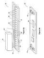
- the apparatus 10 shown in Figure 1 is a stationary apparatus for "cubing" (i.e. measuring the length, width, height of) a package.
- the apparatus 10 of Figure 1 is used by the user placing a package onto the measurement frame 12 of the apparatus 10.
- the apparatus 10, in the embodiment shown in Figure 1 does not operate with a conveyor belt.
- the apparatus 10 is configured to measure three dimensions (L, W, H) of a package. It will be appreciated that the invention described herein can be used to measure one or more dimensions of an object.
- the measurement frame 12 of the apparatus 10 comprises a generally upstanding back portion 14, and a platform 16.
- a package is measured by the package being placed at a measurement position against the back portion 14 and on the platform 16.
- a weight measuring device (not shown) is positioned beneath the platform 16, so that the platform 16 serves as a platform for the weight measuring device.
- the apparatus 10 comprises three dimension measuring devices positioned along three measurement axis.
- the width dimension measuring device 18 is positioned along the width measurement axis 24.
- the length dimension measuring device 20 extends along the length measurement axis 26.
- the height dimension measuring device 22 extends along the height measurement axis 28.
- the dimension measuring devices 18, 20, 22 have substantially flat surfaces that are sized and shaped to receive a package adjacent thereto with the package 32 at a measurement position. Thus, as shown in Figure 1 , a package 32 is received adjacent the dimension measuring devices 18, 20 and 22 at a measurement position.
- each dimension measuring device 18, 20, 22 comprises a line of signal receptors 34 extending along the relevant measurement axis (24, 26 or 28).
- the size of each dimension of the package 32 is determined by determining the nature of the signal being received by each receptor 34, as will be more particularly described below.
- each dimension measuring device comprises a plurality of receptor modules 36 detachably connectable to one another.
- each receptor module 36 includes a linear array of energy receptors 34.
- the receptor modules 36 are connected in series, such that the modules 36 form each of the dimension measuring devices, with a line of receptors 34 along each dimension measuring device.
- each receptor module 36 is configured such that all of the receptor modules are in communication with a central processor 38 (see figure 2 ) of the apparatus 10 to facilitate receipt by the central processor 38 of dimension information from the receptor modules 36.
- the central processor 38 is preferably configured to communicate with each of the dimension measuring devices 18, 20, 22, to receive dimension information from the dimension measuring devices 24, 26 and 28, and to determine each dimension (length, width, height).
- the devices 24, 26 and 28 are communicatively connected to processor 38 via hub 37.
- Hub cables 39 connect devices 24, 26 and 28 to hub 37, and processor cable 41 connects hub 37 to processor 38. It will be appreciated, however, that other forms of connection between devices 24, 26, 28 and processor 38 are possible, and the form of connection used will depend on a number of factors, including physical and size constraints.
- Each of the dimension measuring devices 18, 20, 22 is shown in Figures 1 and 2 as having three modules 36. It will be appreciated by those skilled in the art that the dimension measuring devices need not have this specific number of modules 36 to be comprehended by the invention. Rather, as will be explained more particularly below, the number of modules 36 is variable, and can be adapted by the user of the apparatus 10 to suit the particular circumstances in which the apparatus 10 is used. Thus, the preferred each device 18, 20, 22 may have as little as one module 36, and any higher number of modules 36.
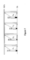
- FIG. 2 is a schematic diagram of the dimension measuring devices 18, 20 and 22, and their connection to the central processor 38.
- the modules 36 each including receptors 34, are connected in series.
- each receptor module is configured such that all of the receptor modules 36 in each dimension measuring device are in communication with the central processor 38 to facilitate receipt by the central processor 38 of dimension information.
- that module 36 might communicate with the central processor through other modules 36 that are positioned between it and the central processor 38.
- each module 36 is preferably configured to permit other modules 36, positioned further away from the central processor 38, to communicate with the central processor 38 through the module 36.
- each module is configured to communicate with the central processor 38 through other modules 36, if necessary, and to allow other modules 36 to communicate with the central processor 38 through it, if necessary.
- a receptor module 36 is shown schematically at Figures 3a and 3b.
- Figure 3a shows the top side of each receptor module, while Figure 3b shows the bottom side.
- Each module 36 preferably includes a micro-controller 40.
- the micro-controller 40 acts as a local controller for each module 36, controlling a number of functions, including the communication functions of the module 36.
- each module 36 includes a connector 42 at each end for connecting to adjacent modules 36. Extending between each connector 42 and the micro-controller 40 is a communication path, by which signals from adjacent modules 36 travel through the particular module 36. Thus, information from an adjacent module 36 will enter through a connector 42, travel through to the micro-controller 40, continue through another communication path and out through the other connector 42 to the other adjacent module 36.
- the micro-controller 40 also preferably receives power through the connector 42, in order to power the operation of the micro-controller 40.
- the micro-controller 40 is operatively connected to each receptor 34, such that the output from each receptor 34 can be read by the micro-controller 40. It will be appreciated that according to the present invention, the dimensions of the package 32 (or other object) are determined with reference to the output of receptors 34 in response to the signals they are receiving.
- the receptors 34 comprise phototransistors, responsive to light.
- the modules 36 each include a unified energy source 46 thereon.
- the unified energy sources 46 are positioned along the dimension measuring devices 18, 20, 22 to form a composite unified energy source 48 for each of the devices 18, 20, 22.
- the dimensions of the package 32 are determined, generally, by actuating the unified energy source 46, and reading the output of the receptors 34. With the package 32 received against the surfaces 30, light from the unified energy source 46 will bounce off the package and be received by the receptors 34. However, at locations where the package 32 does not reach, there will be no energy reflection off of the package 32, and the output of such receptors 34 will reflect the fact that the energy from the unified energy source 46 is not reflecting off the package onto the receptors 34.
- the unified energy source comprises a row of infrared LEDs 50, with each of the LEDs 50 being positioned in close proximity to adjacent LEDs 50.
- the purpose of such close positioning is to cause the unified energy source 46 to deliver a substantially uniform light signal, rather than a punctuated signal with peaks at each LED 50, and valleys between LEDs 50.
- Figure 3a shows an example of unified energy source 46 having closely adjacent LEDs 50.
- Substantially uniform light output 52 is shown. As can be seen, output 52 is substantially uniform as it hits the package 32, without substantial peaks and valleys.
- the relationship between the number of discrete energy sources (example: LED 50) that form a unified energy source and the number of receptors 34 is variable. For example, there need not be a receptor 34 for each LED 50, and in fact, in the preferred embodiment, there are substantially fewer receptors 34 than LEDs 50.
- the number of discrete energy sources that form the unified energy source is determined by the quantity and configuration required to provide uniform energy coverage 52 for all the receptors in a receptor module (36).
- the preferred embodiment of the invention includes unified energy sources 48, comprising a row of closely adjacent LEDs 50, it will be appreciated that other methods of measuring dimensions are possible.
- the energy source could comprise a fluorescent light source, or other types of energy sources such as ultrasonic, radio, radar or other suitable signal or energy type.
- the apparatus 10 may include no signal sources at all, and package size may be determined by measuring the differences in ambient light incident upon different receptors 36.
- signal sources could be mounted not on the modules 34, but rather, apart from the modules 34, so that the package 32, when placed in the frame 12, would block light from said sources from reaching certain receptors 34, thus permitting determination of the dimensions of the package 32.
- Other possible variations include the use of signals other than light (e.g. ultrasonic signals).
- receptors 36 are positioned so that differences in the amount of energy reaching different receptors allow the apparatus 10 to determine the dimensions of a package 32.
- the receptors 34 would need to be compatible with the energy being received. Also, most preferably, the energy level should be consistent (i.e. not flicker or fade).
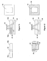
- FIGs 4a and 4b show how the modules 36 fit together. As shown, adjacent modules 36 connect together in series by means of a bridging board 44 configured to receive connectors 42 from both adjacent modules 36. As can be seen most clearly in Figure 3b , connectors 42 are arranged such that the module 36 cannot be plugged into the bridging board 44 unless the module 36 is oriented correctly. This prevents improper installation of the modules 36.
- Figures 4c and 4d show the module holders 54 which hold the modules 36.
- the holders 54 are formed by aluminum extrusion, though other compositions and modes of formation are also comprehended.
- the holders 54 each include two holding slots 56 for receiving the edges of the modules 36 to support them in place.
- the modules 36 are inserted facing outward, i.e. with the receptors 34 and LEDs 50 facing toward the surfaces 30.
- the devices 18, 20, 22 also preferably include lenses 58 not claimed, adjacent to whose outer surface 30 receives the package 32 is positioned for measurement.
- the lenses 58 are carried in lens holding slots 60, formed in holder 54, and function to protect the sources 46 and receptors 34 while passing the energy used for measurement.
- the lenses 58 are configured to permit the passing therethrough of the signal sensed by the receptors 34.
- the lens 58 are light transmissive (most preferably, transparent and colourless).
- the lenses 58 are preferably scratch resistant to prevent scratches from interfering with signal transmission.
- the modules 36 for each device (18, 20, 22) are connected in series using connectors 42 and boards 44. Then, they are inserted into slots 56 from the edge of holder 54, holder 54 being positioned within the frame 12. Then, lens 58 is inserted into slot 60 from the end of holder 54.
- lenses 58 are typically imperfectly transparent. In other words, some of the infrared light from the LEDs 50 will, instead of passing through the lens 58 and hitting the package 32, reflect off of the lens 58 and hit the module 36. Thus receptors 34 will receive some energy from the source 34 that never reflected off of the package 32, but rather, reflected off of the lens 58. The result is an "energy fog” or "infrared fog” 84 around the receptors 34.
- Figure 12 illustrates how the fog 84 is created, and also, how the package 32 appears to the receptors 34 and processor 38 through the fog 84. As can be seen, the contrast between the package and its surrounding is substantially reduced when there is a fog 84, thus rendering it more difficult for the processor 38 to discern the edges of the package 32.
- the apparatus 10 includes a segmented lens 58 for reducing or eliminating fog 84.
- Segmented lens 58 comprising segments 58a and 58b, is shown in Figure 13 .
- the lens 58 is divided into two segments by opaque divider 86, which extends along the length of lens 58, and is positioned above and between receptors 34 and source 48 when the lens 58 is installed.
- the divider 86 is positioned and sized such that energy that is emitted from source 48, that would otherwise have reflected off of lens 58 and been incident upon a receptor 34, instead strikes non-reflective divider 86.
- the divider is also sized and positioned such that light from source 48 can move past divider 86, strike package 32, and reflect back to receptors 34 by moving past the opposite side of divider 86.
- divider 86 reduces or blocks fog 84, while allowing light reflecting off of package 32 to pass, thus permitting object measurement.
- each receptor 34 may produce different outputs in response to identical inputs.
- some receptors 34 may produce various non-zero outputs in response to zero input signals.
- the same non-zero input signal may produce different outputs in different receptors 34.
- the purpose of this first calibration step is to ensure that the raw output from each receptor 34 is converted to information that can be validly compared to information received from other receptors 34.
- each receptor 34 is exposed to a maximum signal, and its output is measured. Then, the receptor 34 is exposed to a minimum signal (i.e.
- raw dimension information i.e., in the preferred embodiment, the output signal from the receptor 34
- adjusted dimension information can be usefully compared with the adjusted dimension information from other receptors 34.
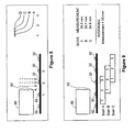
- a preferred method for the first calibration step is shown in Figures 5, 6 and 7 .
- a 100% reflecting calibration object 62 is placed over the receptors 34, and the source 48 is actuated.
- the maximum raw signal output of four receptors 34 is shown. As shown in Figure 5 , these maximum signal outputs are all different from one another. The maximum raw signal levels for each receptor 34 is recorded and stored.
- an opaque calibration object 64 which reflects no signal, and permits no signals to penetrate from the other side of it, is placed over the receptors 34.
- This is a minimum signal environment, and, theoretically, the output from each receptor 34 should be zero.
- the minimum raw signal output as shown in Figure 6 are not equal to zero and differ from one another. The minimum raw signal level for each receptor 34 is recorded and stored.
- mapping functions for each of the four receptors 34 are shown in Figure 7 .
- the maximum signal output is mapped to a predetermined reference maximum, represented by the "100%" reference level shown in Figure 7 .
- each minimum signal output is mapped to a predetermined reference minimum, represented in Figure 7 by the "0%" reference minimum.
- the maximum and minimum raw signal levels for each receptor 34, as well as the mapping function for each receptor 34, are stored in the local controller 40 of the module 36 which contains the particular receptor 34.
- this calibration information maps the output of each receptor 34 to a predetermined reference maximum that is standard for all modules 36
- the module 36 can be used in any apparatus 10 without repeating the first calibration step.
- the module 36 can be used in any apparatus 10 without repeating the first calibration step, and can be moved from one apparatus 10 to the other without repeating the first calibration step.
- This structure provides substantial flexibility to the apparatus 10. If, because of large packages 32, more modules 36 are needed for an apparatus 10, they can be easily added. Similarly, used and/or defective modules 36 can be easily replaced.
- the central processor 38 could store the calibration information for each receptor 34.
- such a configuration is much less preferred, because it would tend to limit the flexibility and substitutability of the modules 36.
- the controllers 40 are programmed to communicate with the processor 38 when installed, or when any modules 36 are added or removed, and to number themselves according to their position along the chain of modules 36 in each of the devices 18, 20, 22.
- the processor 38 then has address information allowing it to determine where each module 36 is positioned, and thus, where each receptor 34 is positioned.
- modules 36 are preferably of standard configuration (i.e. they are all preferably substantially identical in structure and function). This results in the modules 36 being interchangeable as described above. Furthermore, in this manner, the processor 38 knows the position of every receptor 34 positioned on any installed module 36. The result is that the dimensions of objects can be precisely measured, as described more particularly below.
- the modules 36 are configured such that the space between adjacent receptors 34, on the module 36, is constant.
- the modules 36 are also preferably configured such that when modules 36 are connected in series to form one of the devices 18, 20, 22 having a line of receptors 34, the space between adjacent receptors 34 on the device 18, 20, 22 is constant.
- the devices 18, 20, 22 are calibrated using a second calibration step.
- the second calibration step is preferably executed when the modules 36 are connected in series and are connected to the processor 38.
- the information generated by the second calibration step is stored in the memory of the processor 38, in other memory serving the apparatus 10 as a whole, or in memory serving at least one of the devices 18, 20, 22 or as a whole.
- the second calibration step is illustrated schematically at Figure 8 .
- a calibration group of N adjacent receptors is used to generate receptor response information.
- N may be any integer greater than zero, though the second calibration step is most effective for improving measurement precision and accuracy when N is an integer greater than 1. In the example shown in Figure 8 , N equals 3.
- the outputs from all of the receptors 34 are mapped to a predetermined reference that is constant for all receptors 34 (this was done at the first calibration step). Therefore, any two adjusted receptor responses can be validly compared. If the adjusted outputs of two receptors 34 are the same, then it can be assumed that the two signal inputs received by the two receptors 34 were substantially the same. Similarly, if receptor X's adjusted output was a certain fraction of receptor Y's adjusted output, then it can be assumed that the signal received by receptor X was approximately that same fraction of the signal received by receptor Y, where receptors X and Y can be any two receptors in the devices 18, 20, 22.
- the calibration object 80 is positioned at a plurality of calibration positions in the effect area of the N adjacent receptors (labelled 1, 2, 3 in Figure 8 ).
- the plurality of calibration positions will be referred to as M calibration positions, where M is an integer greater than 1.
- four of the M positions are indicated by the characters A, B, C, D for the purposes of illustration.
- the calibration object 80 thus mimics a package 32 having an edge 82 that is positioned at the M positions A, B, C, D, etc. when placed in the measurement position.
- Effect area means the area along the measurement axis near the N receptors where a small change in the position of edge 82 of object 80 will change the output of one or more of the N adjacent receptors. That effect is shown at the "receptor response" graph of Figure 8 .
- receptor 1 which is mostly covered by the object 80, receives energy from the source 48, and shows a high output.
- Receptors 2 and 3 receiving little or no reflected energy at this position, have low outputs.
- the response of receptor 1 remains about the same, but receptors 2 and 3 receive slightly more reflected energy from the source 48, and their outputs are higher.
- receptor 2 is now partly covered by the object 80, and its output is therefore higher still.
- Receptor 3 receives more reflected energy from the source 48 because the object edge is closer to it, and its output is therefore higher.
- receptor 2 is now substantially covered by object 80, and has an output almost identical to that of receptor 1.
- Receptor 3 is now closer to edge 82, receives more reflected energy from source 48, and has a higher output.
- the first calibration step has been performed prior to this second calibration step.
- the invention contemplates the use of receptors 34 that have not undergone the first calibration step.
- the source 48 is actuated to generate a calibration set of receptor outputs for each of the M positions.
- the calibration set of receptor outputs for each of the N receptors at each of the plurality of positions (for a total of M calibration sets of receptor outputs) is read and stored, preferably in the processor 38. It will be appreciated that because of the first calibration step, the adjusted outputs of all receptors 34 are comparable. Thus, the second calibration step needs only to be performed on a single group of N adjacent receptors in the apparatus 10. The results of this second calibration step can then be applied to all groups of N adjacent receptors 34 on the devices 18, 20, 22.
- each calibration set of receptor outputs also represents a corresponding one out of the M positions within the effect area of any other group of N adjacent receptors.
- the measurement of packages not claimed 32 preferably works as follows.
- An apparatus 10, comprising devices 18, 20 and 22, is provided.
- the devices 18, 20 and 22 are each comprised of a plurality of modules 36 connected in series and installed in the frame 12.
- the modules 36 have been calibrated using the preferred first calibration step described above.
- the mapping functions for each receptor 34 which functions standardize the raw output of receptors 34 to comparable adjusted outputs, are stored on the local controller 40 of the module 36 carrying the relevant receptor.
- the preferred second calibration step is performed.
- a representative group of N adjacent receptors is used for the second calibration step, and the calibration sets of outputs are stored in the processor 38 or other memory used for a device 18, 20, 22 as a whole, or apparatus 10 as a whole. Because receptor outputs were standardized in the first calibration step, the second calibration step only needs to be performed on one set of N adjacent receptors 34, and the results can be applied to all other sets of N adjacent receptors 34 on the apparatus 10.
- a package 32 is placed in a measurement position on the frame 12.
- the source 48 on each device 18, 20, 22 is actuated, and the outputs of each receptor 34 (i.e. raw dimension information) are read and adjusted by the local controllers 40 via the mapping functions for each receptor 34 stored therein.
- the adjusted receptor outputs i.e. adjusted dimension information
- the processor 38 stores, or has access to, the stored receptor response information from the second calibration step, consisting of a calibration set of receptor outputs for the set of N adjacent receptors 34 at each of the calibration positions (e.g. see positions A, B, C, D in Figure 8 ). This gives a total of M calibration sets of receptor outputs.
- the processor 38 reads the adjusted receptor outputs from the modules 36, thus creating a measurement set of receptor outputs (i.e. a set of receptor outputs obtained for measurement). For consecutive groups of N adjacent receptors, the processor 38 observes (i.e. looks at) the measurement set of receptor outputs. The processor 38 tries to match the measurement set of receptor outputs from that group of N adjacent receptors to a calibration set of receptor outputs.
- the processor 38 determines the size of the dimension of the package 32.
- N there are two consecutive groups of N adjacent receptors 34.
- the processor 38 looks at the measurement set of receptor outputs for the first N (i.e. 3) receptors, and seeks to match that set to a calibration set of receptor outputs. If a match is found, the processor 38, using its knowledge of which position within the N receptors each calibration set of receptor outputs corresponds to, and in which group of N receptors the match was found, determines the position of the package edge.
- the processor 38 moves on to the next group of N receptors (receptors 4, 5 and 6) and attempts to match the measurement set of receptor outputs to one of the calibration set of receptor outputs. The same matching attempts take place. Note that, as explained above, the same calibration sets of receptor outputs are used for every group of N adjacent receptors, because receptor outputs were standardized in the first calibration step. By contrast, the measurement set of receptor outputs may be different for each group of N receptors, depending on where the edge of the package is located.
- the processor 38 is programmed to discern an edge pattern within the measurement set of receptor outputs, even though the specific magnitudes of receptor outputs may vary for different packages 32.
- a feature of a particular package 32 may present the profile of edge even where there is no such edge.
- a black package bearing a white label might present such a phantom edge profile. Therefore, the processor 38 is preferably programmed with algorithms to recognize phantom edges and filter them out before establishing a measurement of a dimension of the package 32.
- the precision with which the processor 38 can determine the size of the dimension depends on the number of calibration positions employed in the second calibration step. If there is a calibration position every 1 mm, for example, then the measurement can theoretically be precise to within 0.5 mm when the calibration set of receptor outputs is selected during measurement, though it will be appreciated that other factors can affect precision. Thus, if the distance between calibration positions is greater, measurements will be less precise; if it is smaller, they will be more precise.
- N is chosen according to the desired precision, and according to the spacing of receptors 34. In general, given a particular spacing of receptors 34, a greater N will result in a more precise measurement. However, a greater N also requires greater computing power during measurements, and greater storage requirements for calibration data. Therefore, in any particular measurement environment, N can be chosen so as to optimize this trade-off.
- Figure 9 shows an alternative method not claimed of measuring the size of the dimension of the package 32.
- the processor looks at the measurement set of outputs for consecutive (i.e. non-overlapping) groups of N receptors.
- the consecutive groups of N receptors it is also possible for the consecutive groups of N receptors to be overlapping, as shown in Figure 9 .
- N 3, but each successive group of N receptors is offset by only one from the previous group, so that each group overlaps by two receptors.
- the main result of such a measurement approach is that, as shown in Figure 9 , more that one group of N receptors can provide a match between the measurement set of receptor outputs and a calibration set of receptor outputs.
- multiple measurements can be made of the same dimension. Then, the measurements can be averaged to determine a final measurement.
- This method has the advantage of greater accuracy, in that a single measurement has greater potential for large error due to some unforeseen circumstances than an average of multiple measurements.
- the processor 38 may be contained within the frame 12. Alternatively, the processor 38 may be separate, e.g. part of a distinct computer associated with the frame. What is preferred is that the apparatus 10 include a processor 10 to operate the apparatus 10, including calibration, sizing, and shipping charge calculation.
- the apparatus 10 include a display to display size and shipping charge information.
- This display may be integral with the frame 12, or consist of a separate computer screen. Other display configurations are also comprehended by the invention.
- the source 48 preferably comprises a line of LEDs 50 in close proximity to one another.
- the source 48 is actuated, as are the receptors 34.
- the receptors 34 and source 48 are preferably actuated by progressive scanning (i.e. actuation of receptors and LEDs in succession rather than all at once).
- the LEDs 50 can be progressively actuated and de-actuated in multi-unit increments (e.g. five at a time), as can the receptors 34. Alternatively, they can be actuated and de-actuated one at a time. What is preferred is that sufficient amounts of signal be present when a particular receptor 34 is actuated to ensure that the receptor 34 receives all of the signal that it is supposed to receive.
- Progressive scanning is shown at Figures 10a-c .
- Progressive scanning provides two main benefits. First, it saves electrical power. As the output from each receptor 34 is read, there is no need to have all of the other receptors turned on, nor is there any need to turn on portions of the source 48 far from the receptor 34 being read. Thus, progressive scanning reduces the amount of energy used during package measurement.
- controllers 40 control both the source 46 and the reading of the receptors 34 (though it will be appreciated that the invention also comprehends the processor 38 controlling these functions).
- each receptor 34 during measurement, is actuated and read shortly before the source 48 in the vicinity of the receptor 34 is actuated.
- the purpose of the early actuation of receptors 34 is to allow a reading to be taken corresponding to the effect of ambient light on each receptor 34.
- the source 48 is actuated in the vicinity of the receptor 34, it is read again, and the effect of ambient light is subtracted to provide a true measurement which measures the effect of the source 48 on the receptor and excludes ambient light.
- This scanning process is illustrated at Figure11 .
- the signals from source 48 could be modulated to a particular frequency (say 300 kHz), and receptors 34 could be configured to sense only the modulated signals.
- Other forms of modulation can also be employed. However, modulation is less preferred at present because of cost and physical board size considerations.
- the processor is configured to output measurement data in a number of different formats.
- USB serial data
- network formats e.g. Ethernet
Landscapes
- Physics & Mathematics (AREA)
- General Physics & Mathematics (AREA)
- Fluid Mechanics (AREA)
- Engineering & Computer Science (AREA)
- Technology Law (AREA)
- Length Measuring Devices By Optical Means (AREA)
- Length Measuring Devices With Unspecified Measuring Means (AREA)
Claims (20)
- Rezeptorenmodul (36), umfassend:eine Vielzahl von Signalrezeptoren (34), die im Allgemeinen in einer Reihe angeordnet sind, und ein Substrat, welches die Vielzahl von Signalrezeptoren (34) trägt;lösbare Verbindungsmittel (42) zum Verbinden des Rezeptorenmoduls (36) mit anderen Rezeptorenmodulen (36) in Reihe, um eine Größenmessvorrichtung (18, 20, 22) mit entlang einer Messachse (24, 26, 28) angeordneten Signalrezeptoren (34) zu bilden;wobei das Rezeptorenmodul (36) ferner seine eigene lokale Steuerung (40) umfasst, die der Vielzahl von Signalrezeptoren (34) zugeordnet ist, wobei die lokale Steuerung (40) ausgebildet ist, um vor der Verwendung Kalibrierdaten für die Vielzahl von Signalrezeptoren (34) zu speichern.
- Rezeptorenmodul (36) nach Anspruch 1, wobei das Rezeptorenmodul (36) dazu ausgebildet ist, über mindestens ein anderes Rezeptorenmodul (36) mit einem zentralen Prozessor (38) zu kommunizieren.
- Rezeptorenmodul (36) nach Anspruch 1, wobei das Rezeptorenmodul (36) dazu ausgebildet ist zuzulassen, dass über das Rezeptorenmodul (36) mindestens ein anderes Rezeptorenmodul (36) mit einem zentralen Prozessor (38) kommuniziert.
- Rezeptorenmodul (36) nach Anspruch 1, wobei der Abstand zwischen benachbarten Signalrezeptoren (34) konstant ist.
- Rezeptorenmodul (36) nach Anspruch 1, wobei die Signalrezeptoren (34) derart angeordnet sind, dass, wenn das Rezeptorenmodul (36) mit anderen Rezeptorenmodulen (36) in Reihe verbunden wird, um eine Größenmessvorrichtung (18, 20, 22) zu bilden, der Abstand zwischen benachbarten Signalrezeptoren (34) der Größenmessvorrichtung (18, 20, 22) konstant ist.
- Rezeptorenmodul (36) nach Anspruch 1, wobei das Modul (36) dazu ausgebildet ist, vor der Verwendung kalibriert zu werden und andere Rezeptorenmodule (36) in einer Größenmessvorrichtung (18, 20, 22) zu ersetzen, ohne vor der Verwendung die Kalibrierung zu wiederholen.
- Vorrichtung (10) zum Messen von mindestens einer Abmessung eines Pakets, wobei die Vorrichtung umfasst:eine Größenmessvorrichtung (18, 20, 22), die sich eine Messachse (24, 26, 28) entlang erstreckt und dazu bemessen und ausgestaltet ist, ein Paket (32) an einer Messposition aufzunehmen, und einen zentralen Prozessor (38), der dazu ausgebildet ist, mit der Größenmessvorrichtung (18, 20, 22) zu kommunizieren, Größendaten zu empfangen und die Größe zu ermitteln;wobei die Größenmessvorrichtung (18, 20, 22) eine Vielzahl von Rezeptorenmodulen (36) gemäß einem beliebigen der Ansprüche 1-6 umfasst, welche lösbar miteinander verbunden werden können;wobei jedes Rezeptorenmodul (36) eine Vielzahl von Signalrezeptoren (34) umfasst, die entlang der Messachse (24, 26, 28) voneinander beabstandet sind;wobei die Rezeptorenmodule (36) in Reihe verbunden sind, wobei jedes Rezeptorenmodul (36) derart ausgebildet ist, dass alle aus der Vielzahl von Rezeptorenmodulen (36) mit dem zentralen Prozessor (38) in Kommunikation stehen, um den Empfang von Größendaten durch den zentralen Prozessor (38) zu erleichtern;wobei jedes Rezeptorenmodul (36) seine eigene lokale Steuerung (40) umfasst, welche der Vielzahl von Signalrezeptoren (34) zugeordnet ist, wobei die lokale Steuerung (40) Kalibrierdaten für die Vielzahl von Signalrezeptoren (34) enthält.
- Vorrichtung (10) nach Anspruch 7, wobei jedes Rezeptorenmodul (36) dazu ausgebildet ist, in der Lage zu sein, mit dem zentralen Prozessor (38) über ein oder mehrere andere Rezeptorenmodule (36) zu kommunizieren.
- Vorrichtung (10) nach Anspruch 8, wobei jedes Rezeptorenmodul (36) dazu ausgebildet ist, Kommunikation zwischen mindestens einem anderen Rezeptorenmodul (36) und dem zentralen Prozessor (38) zuzulassen.
- Vorrichtung (10) nach Anspruch 7, wobei die Kalibrierdaten eine Abbildungsfunktion umfassen, welche die maximale Antwort von jedem aus der Vielzahl von Signalrezeptoren (34) auf ein vorgegebenes Bezugsmaximum abbildet und die minimale Antwort von jedem aus der Vielzahl von Signalrezeptoren (34) auf ein vorgegebenes Bezugsminimum abbildet.
- Vorrichtung (10) nach Anspruch 10, wobei das Bezugsmaximum und das Bezugsminimum von Rezeptormodul (36) zu Rezeptormodul (36) konstant sind.
- Vorrichtung (10) nach Anspruch 7 oder 11, wobei die lokale Steuerung (40) dazu ausgebildet ist, Größenrohdaten von der Vielzahl von Signalrezeptoren (34) zu empfangen, die Kalibrierdaten auf die Größenrohdaten anzuwenden, um bereinigte Größendaten zu erzeugen, und die bereinigten Größendaten an den zentralen Prozessor (38) zu übertragen.
- Vorrichtung (10) nach Anspruch 7, wobei jedes Rezeptorenmodul (36) derart ausgebildet ist, dass der Abstand zwischen benachbarten Rezeptoren (34) an jedem Rezeptorenmodul (36) konstant ist.
- Vorrichtung (10) nach Anspruch 7 oder Anspruch 13, wobei jedes Rezeptorenmodul (36) derart ausgebildet ist, dass der Abstand zwischen benachbarten Signalrezeptoren (34) an der Größenmessvorrichtung (18, 20, 22) konstant ist.
- Vorrichtung (10) nach Anspruch 7, wobei die lokale Steuerung (40) dazu ausgebildet ist, Kalibrierdaten zu empfangen, ehe das Rezeptorenmodul (36) mit der Größenmessvorrichtung (18, 20, 22) verbunden wird, die Kalibrierdaten zu speichern und die Kalibrierdaten auf die Messung von Paketen (32) mittels der Größenmessvorrichtung (18, 20, 22) anzuwenden.
- Vorrichtung (10) nach Anspruch 7, wobei jedes Rezeptorenmodul (36) ferner eine Signalquelle (46) umfasst.
- Vorrichtung (10) nach Anspruch 16, wobei die Signalquelle (46) eine einheitliche Signalquelle (46) umfasst.
- Vorrichtung (10) nach Anspruch 17, wobei die einheitliche Signalquelle (46) eine Vielzahl von Signalpunkten (50) umfasst, die in nächster Nähe zueinander angeordnet sind, um über die Länge des Rezeptorenmoduls (36) ein im Wesentlichen einheitliches Signal (52) zu erzeugen.
- Verfahren zum Kalibrieren einer Vielzahl von Signalrezeptoren (34), die an einem Rezeptorenmodul (36) gemäß Anspruch 1 getragen werden, wobei das Rezeptorenmodul (36) dazu ausgebildet ist, mit anderen Rezeptorenmodulen (36) in Reihe verbunden zu werden, um eine Größenmessvorrichtung (18, 20, 22) mit entlang einer Messachse (24, 26, 28) angeordneten Signalrezeptoren (34) zu bilden, wobei das Verfahren folgende Schritte umfasst:für jeden Signalrezeptor (34);(a) Beaufschlagen des Signalrezeptors (34) mit einem maximalen Signal;(b) Messen des Ausgangs des Signalrezeptors (34) von dem maximalen Signal;(c) Beaufschlagen des Signalrezeptors (34) mit einem minimalen Signal;(d) Messen des Ausgangs des Signalrezeptors (34) von dem minimalen Signal;(e) Ermitteln einer Abbildungsfunktion, welche den Ausgang von dem maximalen Signal auf ein vorgegebenes Bezugsmaximum abbildet und den Ausgang von dem minimalen Signal auf ein vorgegebenes Bezugsminimum abbildet;(f) Speichern der Abbildungsfunktion auf der lokalen Steuerung (40), die dem Rezeptorenmodul (36) zugeordnet ist, zur Verwendung bei mehreren Messungen.
- Verfahren nach Anspruch 19, wobei der Schritt des Speicherns das Speichern der Abbildungsfunktion in einem zentralen Prozessor (38) einer Größenmessvorrichtung umfasst.
Applications Claiming Priority (2)
| Application Number | Priority Date | Filing Date | Title |
|---|---|---|---|
| CA2545118A CA2545118C (en) | 2006-04-28 | 2006-04-28 | Device for measuring package size |
| PCT/CA2007/000660 WO2007124568A1 (en) | 2006-04-28 | 2007-04-18 | Device for measuring package size |
Publications (3)
| Publication Number | Publication Date |
|---|---|
| EP2018514A1 EP2018514A1 (de) | 2009-01-28 |
| EP2018514A4 EP2018514A4 (de) | 2012-05-30 |
| EP2018514B1 true EP2018514B1 (de) | 2013-10-02 |
Family
ID=38653145
Family Applications (1)
| Application Number | Title | Priority Date | Filing Date |
|---|---|---|---|
| EP07719587.3A Not-in-force EP2018514B1 (de) | 2006-04-28 | 2007-04-18 | Einrichtung zur messung der packungsgrösse |
Country Status (9)
| Country | Link |
|---|---|
| US (2) | US7373722B2 (de) |
| EP (1) | EP2018514B1 (de) |
| JP (3) | JP2009535607A (de) |
| KR (1) | KR101387414B1 (de) |
| CN (1) | CN101473189B (de) |
| CA (3) | CA2737302C (de) |
| IN (1) | IN2014MN00913A (de) |
| MX (1) | MX2008013862A (de) |
| WO (1) | WO2007124568A1 (de) |
Cited By (1)
| Publication number | Priority date | Publication date | Assignee | Title |
|---|---|---|---|---|
| CN104001673A (zh) * | 2014-05-21 | 2014-08-27 | 苏州博众精工科技有限公司 | 一种自动区分物料机构 |
Families Citing this family (68)
| Publication number | Priority date | Publication date | Assignee | Title |
|---|---|---|---|---|
| CA2737302C (en) * | 2006-04-28 | 2013-06-18 | Global Sensor Systems Inc. | Device for measuring package size |
| CN101281028A (zh) * | 2007-04-02 | 2008-10-08 | 鸿富锦精密工业(深圳)有限公司 | 检测仪 |
| WO2009070696A1 (en) * | 2007-11-26 | 2009-06-04 | Proiam, Llc | Enrollment apparatus, system, and method |
| US20100058767A1 (en) * | 2008-09-05 | 2010-03-11 | General Electric Company | Swirl angle of secondary fuel nozzle for turbomachine combustor |
| US8131654B2 (en) * | 2008-12-11 | 2012-03-06 | Pitney Bowes Inc. | System and method for dimensional rating of mail pieces |
| PL2697149T3 (pl) * | 2011-04-15 | 2019-12-31 | Tamtron Oy | Sposób szacowania objętości |
| EP2573526B1 (de) * | 2011-09-20 | 2013-11-13 | Neopost Technologies | Gerät zur Größenbestimmung von Paketen |
| JPWO2014192080A1 (ja) * | 2013-05-28 | 2017-02-23 | 新光電子株式会社 | 寸法測定装置 |
| WO2014205112A1 (en) * | 2013-06-21 | 2014-12-24 | Quantronix, Inc. | Object dimensioning apparatus, systems and related methods |
| CN104279961A (zh) * | 2014-10-30 | 2015-01-14 | 黑龙江中科诺晟自动化设备开发有限公司 | 药品自动化管理系统的药盒尺寸测量方法 |
| US9600892B2 (en) | 2014-11-06 | 2017-03-21 | Symbol Technologies, Llc | Non-parametric method of and system for estimating dimensions of objects of arbitrary shape |
| US9396554B2 (en) | 2014-12-05 | 2016-07-19 | Symbol Technologies, Llc | Apparatus for and method of estimating dimensions of an object associated with a code in automatic response to reading the code |
| JP6507451B2 (ja) * | 2015-09-11 | 2019-05-08 | パナソニックIpマネジメント株式会社 | 宅配物測定装置 |
| US10352689B2 (en) | 2016-01-28 | 2019-07-16 | Symbol Technologies, Llc | Methods and systems for high precision locationing with depth values |
| US10145955B2 (en) | 2016-02-04 | 2018-12-04 | Symbol Technologies, Llc | Methods and systems for processing point-cloud data with a line scanner |
| US10721451B2 (en) | 2016-03-23 | 2020-07-21 | Symbol Technologies, Llc | Arrangement for, and method of, loading freight into a shipping container |
| US9805240B1 (en) | 2016-04-18 | 2017-10-31 | Symbol Technologies, Llc | Barcode scanning and dimensioning |
| US10776661B2 (en) | 2016-08-19 | 2020-09-15 | Symbol Technologies, Llc | Methods, systems and apparatus for segmenting and dimensioning objects |
| US11042161B2 (en) | 2016-11-16 | 2021-06-22 | Symbol Technologies, Llc | Navigation control method and apparatus in a mobile automation system |
| US10451405B2 (en) | 2016-11-22 | 2019-10-22 | Symbol Technologies, Llc | Dimensioning system for, and method of, dimensioning freight in motion along an unconstrained path in a venue |
| US10354411B2 (en) | 2016-12-20 | 2019-07-16 | Symbol Technologies, Llc | Methods, systems and apparatus for segmenting objects |
| US11449059B2 (en) | 2017-05-01 | 2022-09-20 | Symbol Technologies, Llc | Obstacle detection for a mobile automation apparatus |
| US10949798B2 (en) | 2017-05-01 | 2021-03-16 | Symbol Technologies, Llc | Multimodal localization and mapping for a mobile automation apparatus |
| WO2018204342A1 (en) | 2017-05-01 | 2018-11-08 | Symbol Technologies, Llc | Product status detection system |
| US10591918B2 (en) | 2017-05-01 | 2020-03-17 | Symbol Technologies, Llc | Fixed segmented lattice planning for a mobile automation apparatus |
| US10663590B2 (en) | 2017-05-01 | 2020-05-26 | Symbol Technologies, Llc | Device and method for merging lidar data |
| US10726273B2 (en) | 2017-05-01 | 2020-07-28 | Symbol Technologies, Llc | Method and apparatus for shelf feature and object placement detection from shelf images |
| US11367092B2 (en) | 2017-05-01 | 2022-06-21 | Symbol Technologies, Llc | Method and apparatus for extracting and processing price text from an image set |
| AU2018261257B2 (en) | 2017-05-01 | 2020-10-08 | Symbol Technologies, Llc | Method and apparatus for object status detection |
| WO2018201423A1 (en) | 2017-05-05 | 2018-11-08 | Symbol Technologies, Llc | Method and apparatus for detecting and interpreting price label text |
| JP2019015553A (ja) * | 2017-07-05 | 2019-01-31 | ソニーセミコンダクタソリューションズ株式会社 | 情報処理装置、情報処理方法および個体撮像装置 |
| US10521914B2 (en) | 2017-09-07 | 2019-12-31 | Symbol Technologies, Llc | Multi-sensor object recognition system and method |
| US10572763B2 (en) | 2017-09-07 | 2020-02-25 | Symbol Technologies, Llc | Method and apparatus for support surface edge detection |
| WO2019078884A1 (en) * | 2017-10-20 | 2019-04-25 | Siemens Medical Solutions Usa, Inc. | ELECTRONIC PATIENT BED RULE |
| US10438995B2 (en) * | 2018-01-08 | 2019-10-08 | Spin Memory, Inc. | Devices including magnetic tunnel junctions integrated with selectors |
| US10823572B2 (en) | 2018-04-05 | 2020-11-03 | Symbol Technologies, Llc | Method, system and apparatus for generating navigational data |
| US10809078B2 (en) | 2018-04-05 | 2020-10-20 | Symbol Technologies, Llc | Method, system and apparatus for dynamic path generation |
| US11327504B2 (en) | 2018-04-05 | 2022-05-10 | Symbol Technologies, Llc | Method, system and apparatus for mobile automation apparatus localization |
| US10832436B2 (en) | 2018-04-05 | 2020-11-10 | Symbol Technologies, Llc | Method, system and apparatus for recovering label positions |
| US10740911B2 (en) | 2018-04-05 | 2020-08-11 | Symbol Technologies, Llc | Method, system and apparatus for correcting translucency artifacts in data representing a support structure |
| US11506483B2 (en) | 2018-10-05 | 2022-11-22 | Zebra Technologies Corporation | Method, system and apparatus for support structure depth determination |
| US11010920B2 (en) | 2018-10-05 | 2021-05-18 | Zebra Technologies Corporation | Method, system and apparatus for object detection in point clouds |
| US11090811B2 (en) | 2018-11-13 | 2021-08-17 | Zebra Technologies Corporation | Method and apparatus for labeling of support structures |
| US11003188B2 (en) | 2018-11-13 | 2021-05-11 | Zebra Technologies Corporation | Method, system and apparatus for obstacle handling in navigational path generation |
| US11079240B2 (en) | 2018-12-07 | 2021-08-03 | Zebra Technologies Corporation | Method, system and apparatus for adaptive particle filter localization |
| US11416000B2 (en) | 2018-12-07 | 2022-08-16 | Zebra Technologies Corporation | Method and apparatus for navigational ray tracing |
| US11100303B2 (en) | 2018-12-10 | 2021-08-24 | Zebra Technologies Corporation | Method, system and apparatus for auxiliary label detection and association |
| US11015938B2 (en) | 2018-12-12 | 2021-05-25 | Zebra Technologies Corporation | Method, system and apparatus for navigational assistance |
| US10731970B2 (en) | 2018-12-13 | 2020-08-04 | Zebra Technologies Corporation | Method, system and apparatus for support structure detection |
| CA3028708C (en) | 2018-12-28 | 2025-12-09 | Zebra Technologies Corporation | Method, system and apparatus for dynamic loop closure in mapping trajectories |
| US11960286B2 (en) | 2019-06-03 | 2024-04-16 | Zebra Technologies Corporation | Method, system and apparatus for dynamic task sequencing |
| US11402846B2 (en) | 2019-06-03 | 2022-08-02 | Zebra Technologies Corporation | Method, system and apparatus for mitigating data capture light leakage |
| US11662739B2 (en) | 2019-06-03 | 2023-05-30 | Zebra Technologies Corporation | Method, system and apparatus for adaptive ceiling-based localization |
| US11080566B2 (en) | 2019-06-03 | 2021-08-03 | Zebra Technologies Corporation | Method, system and apparatus for gap detection in support structures with peg regions |
| US11341663B2 (en) | 2019-06-03 | 2022-05-24 | Zebra Technologies Corporation | Method, system and apparatus for detecting support structure obstructions |
| US11151743B2 (en) | 2019-06-03 | 2021-10-19 | Zebra Technologies Corporation | Method, system and apparatus for end of aisle detection |
| US11200677B2 (en) | 2019-06-03 | 2021-12-14 | Zebra Technologies Corporation | Method, system and apparatus for shelf edge detection |
| CN110398203B (zh) * | 2019-08-14 | 2021-06-04 | 东风设备制造有限公司 | 长距离激光测长方法及装置 |
| US11507103B2 (en) | 2019-12-04 | 2022-11-22 | Zebra Technologies Corporation | Method, system and apparatus for localization-based historical obstacle handling |
| US11107238B2 (en) | 2019-12-13 | 2021-08-31 | Zebra Technologies Corporation | Method, system and apparatus for detecting item facings |
| US11822333B2 (en) | 2020-03-30 | 2023-11-21 | Zebra Technologies Corporation | Method, system and apparatus for data capture illumination control |
| US11450024B2 (en) | 2020-07-17 | 2022-09-20 | Zebra Technologies Corporation | Mixed depth object detection |
| US11593915B2 (en) | 2020-10-21 | 2023-02-28 | Zebra Technologies Corporation | Parallax-tolerant panoramic image generation |
| US11392891B2 (en) | 2020-11-03 | 2022-07-19 | Zebra Technologies Corporation | Item placement detection and optimization in material handling systems |
| US11847832B2 (en) | 2020-11-11 | 2023-12-19 | Zebra Technologies Corporation | Object classification for autonomous navigation systems |
| CN113203430B (zh) * | 2021-03-29 | 2022-08-26 | 深圳市华怡丰科技有限公司 | 光电传感器校准方法、系统、光电传感器及可读存储介质 |
| US11954882B2 (en) | 2021-06-17 | 2024-04-09 | Zebra Technologies Corporation | Feature-based georegistration for mobile computing devices |
| US20240347395A1 (en) * | 2023-04-13 | 2024-10-17 | Quantronix, Inc. | Object dimensioning apparatus and related methods |
Family Cites Families (48)
| Publication number | Priority date | Publication date | Assignee | Title |
|---|---|---|---|---|
| US2736095A (en) * | 1956-02-28 | Krauss | ||
| US2149958A (en) * | 1938-04-11 | 1939-03-07 | Fox Marvin | Measuring system |
| US2708368A (en) | 1950-12-21 | 1955-05-17 | Continental Silver Co Inc | Equipment for rating by volume, weight, and zone |
| US2688878A (en) * | 1951-03-28 | 1954-09-14 | Continental Silver Co Inc | Equipment for rating by volume, weight, and zone |
| JPS55131708A (en) * | 1979-04-02 | 1980-10-13 | Kurabo Ind Ltd | Object position measuring device |
| US4268967A (en) * | 1979-09-14 | 1981-05-26 | Brana Lejo C | Package sizer |
| JPS5817308A (ja) * | 1981-07-23 | 1983-02-01 | Nireko:Kk | インキ供給量測定装置 |
| CA1253620A (en) | 1985-04-30 | 1989-05-02 | Jon Claesson | Method relating to three dimensional measurement of objects |
| US4803371A (en) | 1987-09-30 | 1989-02-07 | The Coe Manufacturing Company | Optical scanning method and apparatus useful for determining the configuration of an object |
| GB2222702B (en) * | 1988-07-25 | 1993-03-10 | Nissan Motor | Wheel slippage suppresive throttle control system for automotive internal combustion engine |
| US5042015A (en) | 1989-09-01 | 1991-08-20 | Quantronix, Inc. | Measuring method and apparatus |
| US5606534A (en) | 1989-09-01 | 1997-02-25 | Quantronix, Inc. | Laser-based dimensioning system |
| JPH0643684Y2 (ja) * | 1990-10-08 | 1994-11-14 | 新光電子株式会社 | 寸法重量測定装置 |
| AT396181B (de) | 1990-12-10 | 1993-06-25 | Sprecher Energie Oesterreich | Einrichtung zum erfassen der masse eines gegebenenfalls bewegten gegenstandes |
| WO1992017857A1 (en) * | 1991-03-27 | 1992-10-15 | Brandt, Inc. | Currency note width detector |
| NO912756L (no) * | 1991-07-12 | 1993-01-13 | Cargoscan As | Fremgangsmaate og system for dimensjonsmaaling av en tredimensjonal gjenstand. |
| JPH0599620A (ja) * | 1991-10-14 | 1993-04-23 | Olympus Optical Co Ltd | エツジ検出装置 |
| JPH05172535A (ja) * | 1991-12-24 | 1993-07-09 | Kawasaki Steel Corp | ピーク点検出方法及びキャリブレーション方法 |
| US5331118A (en) * | 1992-11-27 | 1994-07-19 | Soren Jensen | Package dimensional volume and weight determination system for conveyors |
| JPH07332925A (ja) * | 1994-06-03 | 1995-12-22 | Keyence Corp | 測定装置 |
| US5530548A (en) * | 1994-11-07 | 1996-06-25 | Automotive Systems Laboratory, Inc. | Calibratable optical distance sensing system and method |
| JPH07286815A (ja) * | 1995-05-11 | 1995-10-31 | Nikon Corp | 位置検出装置 |
| JPH1038683A (ja) * | 1996-07-22 | 1998-02-13 | Nikon Corp | 光量検出装置 |
| US5878379A (en) | 1996-12-31 | 1999-03-02 | Pitney Bowes Inc. | Coarse volume measurement with interlock |
| US5808912A (en) | 1996-12-31 | 1998-09-15 | Pitney Bowes Inc. | Method for dimensional weighing utilizing point determination |
| US5815274A (en) | 1996-12-31 | 1998-09-29 | Pitney Bowes Inc. | Method for dimensional weighing by spaced line projection |
| US5793652A (en) | 1996-12-31 | 1998-08-11 | Pitney Bowes Inc. | Dimensional weighing apparatus |
| US5909013A (en) | 1996-12-31 | 1999-06-01 | Pitney Bowes Inc. | Dimensional weighing utilizing a following arm mechanism |
| US5770864A (en) | 1996-12-31 | 1998-06-23 | Pitney Bowes Inc. | Apparatus and method for dimensional weighing utilizing a laser scanner or sensor |
| US5734476A (en) | 1996-12-31 | 1998-03-31 | Pitney Bowes Inc. | Method for dimensional weighing with optics |
| US5777746A (en) | 1996-12-31 | 1998-07-07 | Pitney Bowes Inc. | Apparatus and method for dimensional weighing utilizing a mirror and/or prism |
| US5841541A (en) | 1996-12-31 | 1998-11-24 | Pitney Bowes Inc. | Apparatus and method for dimensional weighing utilizing a rotating sensor |
| US5914463A (en) | 1996-12-31 | 1999-06-22 | Pitney Bowes Inc. | Low cost dimensional determining system |
| CA2254851A1 (en) | 1997-03-11 | 1998-09-17 | Werner Haug | Device for measuring volume |
| JP4125422B2 (ja) * | 1998-05-07 | 2008-07-30 | 株式会社キーエンス | 多光軸光電スイッチ |
| US6373579B1 (en) | 1999-05-26 | 2002-04-16 | Hand Held Products, Inc. | Portable measurement apparatus for determinging the dimensions of an object and associated method |
| JP2002213946A (ja) * | 2001-01-19 | 2002-07-31 | Seiko Precision Inc | イメージ信号出力方法、イメージ信号出力装置、測距装置及び撮像装置 |
| CA2334375A1 (en) * | 2001-02-02 | 2002-08-02 | 3Dm Devices Inc. | Laser micrometer |
| US6662458B1 (en) * | 2001-02-08 | 2003-12-16 | Paul Antonelli | Leveling rod and leveling method |
| US20020121025A1 (en) * | 2001-03-02 | 2002-09-05 | Leite Shawn S. | Modular level |
| JP2003285472A (ja) * | 2002-03-28 | 2003-10-07 | Canon Inc | 画像形成装置 |
| JP3861751B2 (ja) * | 2002-05-31 | 2006-12-20 | 日立エンジニアリング株式会社 | 形状寸法検査装置 |
| CA2388895C (en) | 2002-06-04 | 2008-11-18 | Global Sensor Systems Inc. | A billing system and method for determining transportation charges for packages |
| JP2004045128A (ja) * | 2002-07-10 | 2004-02-12 | Pentax Corp | 校正基準器、該校正基準器を用いた画像検査装置校正のための画像処理方法、および画像検査装置校正方法 |
| JP2004061198A (ja) * | 2002-07-26 | 2004-02-26 | Toyo Kanetsu Solutions Kk | 被測定物の寸法測定装置及び方法、並びにフォトセンサ基板 |
| US6850464B2 (en) | 2003-02-05 | 2005-02-01 | Quantronix, Inc. | Dimensioning system and method of dimensioning |
| JP3981693B2 (ja) * | 2006-03-20 | 2007-09-26 | 株式会社キーエンス | 多光軸光電センサ |
| CA2737302C (en) * | 2006-04-28 | 2013-06-18 | Global Sensor Systems Inc. | Device for measuring package size |
-
2006
- 2006-04-28 CA CA2737302A patent/CA2737302C/en not_active Expired - Lifetime
- 2006-04-28 CA CA2737169A patent/CA2737169C/en not_active Expired - Lifetime
- 2006-04-28 CA CA2545118A patent/CA2545118C/en not_active Expired - Lifetime
- 2006-05-12 US US11/433,096 patent/US7373722B2/en not_active Ceased
-
2007
- 2007-04-18 KR KR1020087029054A patent/KR101387414B1/ko not_active Expired - Fee Related
- 2007-04-18 WO PCT/CA2007/000660 patent/WO2007124568A1/en not_active Ceased
- 2007-04-18 MX MX2008013862A patent/MX2008013862A/es active IP Right Grant
- 2007-04-18 JP JP2009506873A patent/JP2009535607A/ja active Pending
- 2007-04-18 CN CN200780022762XA patent/CN101473189B/zh not_active Expired - Fee Related
- 2007-04-18 IN IN913MUN2014 patent/IN2014MN00913A/en unknown
- 2007-04-18 EP EP07719587.3A patent/EP2018514B1/de not_active Not-in-force
-
2012
- 2012-01-10 US US13/374,734 patent/USRE44238E1/en active Active
- 2012-02-22 JP JP2012036268A patent/JP2012108153A/ja active Pending
-
2013
- 2013-05-14 JP JP2013102284A patent/JP5508570B2/ja not_active Expired - Fee Related
Cited By (1)
| Publication number | Priority date | Publication date | Assignee | Title |
|---|---|---|---|---|
| CN104001673A (zh) * | 2014-05-21 | 2014-08-27 | 苏州博众精工科技有限公司 | 一种自动区分物料机构 |
Also Published As
| Publication number | Publication date |
|---|---|
| CA2545118A1 (en) | 2007-10-28 |
| USRE44238E1 (en) | 2013-05-28 |
| WO2007124568A1 (en) | 2007-11-08 |
| CN101473189A (zh) | 2009-07-01 |
| CA2737302C (en) | 2013-06-18 |
| CA2737169C (en) | 2014-04-01 |
| US7373722B2 (en) | 2008-05-20 |
| EP2018514A1 (de) | 2009-01-28 |
| EP2018514A4 (de) | 2012-05-30 |
| KR101387414B1 (ko) | 2014-04-21 |
| CN101473189B (zh) | 2011-07-06 |
| JP2013174617A (ja) | 2013-09-05 |
| CA2737302A1 (en) | 2007-10-28 |
| JP2012108153A (ja) | 2012-06-07 |
| KR20090016562A (ko) | 2009-02-16 |
| CA2545118C (en) | 2011-07-05 |
| US20070261255A1 (en) | 2007-11-15 |
| JP5508570B2 (ja) | 2014-06-04 |
| CA2737169A1 (en) | 2007-10-28 |
| IN2014MN00913A (de) | 2015-04-17 |
| MX2008013862A (es) | 2008-11-14 |
| HK1132323A1 (en) | 2010-02-19 |
| JP2009535607A (ja) | 2009-10-01 |
Similar Documents
| Publication | Publication Date | Title |
|---|---|---|
| EP2018514B1 (de) | Einrichtung zur messung der packungsgrösse | |
| US6373579B1 (en) | Portable measurement apparatus for determinging the dimensions of an object and associated method | |
| JP5396015B2 (ja) | 寸法指示及び計量システム | |
| US7403900B2 (en) | Franking system and method | |
| US7214954B2 (en) | Method for operating optical sensors | |
| US7650289B2 (en) | Billing system and method for determining transportation charges for packages | |
| CA2314251C (en) | Article classifying system and article dimension measuring apparatus | |
| JP7060360B2 (ja) | 送付物処理システムにおける平坦な送付物の長さを測定するための方法および方法を実施するための装置 | |
| AU6343596A (en) | In-motion dimensioning system for cuboidal objects | |
| US5834706A (en) | Method and apparatus for verifying the contents of packages delivered to or leaving a warehouse | |
| JP5224405B2 (ja) | バーコードリーダ、バーコードラベル貼付システム、およびバーコードシンボル印刷システム | |
| JP2001171839A (ja) | 物品の積み付け段数検知システム | |
| HK1132323B (en) | Device for measuring package size | |
| US7480469B2 (en) | System and method for determining an amount of toner mass on a photoreceptor | |
| US11906284B2 (en) | Method and device for detecting the edge of an object | |
| EP0105061B1 (de) | Lumineszierender Adressenstrichkode | |
| GB2099761A (en) | Luminescent address bar codes | |
| JP2000337837A (ja) | リード検査方法及び装置 |
Legal Events
| Date | Code | Title | Description |
|---|---|---|---|
| PUAI | Public reference made under article 153(3) epc to a published international application that has entered the european phase |
Free format text: ORIGINAL CODE: 0009012 |
|
| 17P | Request for examination filed |
Effective date: 20081128 |
|
| AK | Designated contracting states |
Kind code of ref document: A1 Designated state(s): AT BE BG CH CY CZ DE DK EE ES FI FR GB GR HU IE IS IT LI LT LU LV MC MT NL PL PT RO SE SI SK TR |
|
| AX | Request for extension of the european patent |
Extension state: AL BA HR MK RS |
|
| RIN1 | Information on inventor provided before grant (corrected) |
Inventor name: TEAL, TODD Inventor name: COOPER, GORDON C. Inventor name: HULL, LORNE Inventor name: COOPER, RICHARD H. |
|
| A4 | Supplementary search report drawn up and despatched |
Effective date: 20120504 |
|
| RIC1 | Information provided on ipc code assigned before grant |
Ipc: G01B 11/02 20060101ALI20120426BHEP Ipc: G07B 17/00 20060101ALI20120426BHEP Ipc: G01D 3/02 20060101ALI20120426BHEP Ipc: G01D 18/00 20060101ALI20120426BHEP Ipc: B07C 5/10 20060101ALI20120426BHEP Ipc: G01B 21/02 20060101AFI20120426BHEP |
|
| DAX | Request for extension of the european patent (deleted) | ||
| GRAP | Despatch of communication of intention to grant a patent |
Free format text: ORIGINAL CODE: EPIDOSNIGR1 |
|
| INTG | Intention to grant announced |
Effective date: 20130506 |
|
| GRAS | Grant fee paid |
Free format text: ORIGINAL CODE: EPIDOSNIGR3 |
|
| GRAA | (expected) grant |
Free format text: ORIGINAL CODE: 0009210 |
|
| AK | Designated contracting states |
Kind code of ref document: B1 Designated state(s): AT BE BG CH CY CZ DE DK EE ES FI FR GB GR HU IE IS IT LI LT LU LV MC MT NL PL PT RO SE SI SK TR |
|
| REG | Reference to a national code |
Ref country code: GB Ref legal event code: FG4D |
|
| REG | Reference to a national code |
Ref country code: CH Ref legal event code: EP Ref country code: AT Ref legal event code: REF Ref document number: 634816 Country of ref document: AT Kind code of ref document: T Effective date: 20131015 |
|
| REG | Reference to a national code |
Ref country code: IE Ref legal event code: FG4D |
|
| REG | Reference to a national code |
Ref country code: DE Ref legal event code: R096 Ref document number: 602007033116 Country of ref document: DE Effective date: 20131128 |
|
| REG | Reference to a national code |
Ref country code: NL Ref legal event code: T3 |
|
| REG | Reference to a national code |
Ref country code: AT Ref legal event code: MK05 Ref document number: 634816 Country of ref document: AT Kind code of ref document: T Effective date: 20131002 |
|
| PG25 | Lapsed in a contracting state [announced via postgrant information from national office to epo] |
Ref country code: SI Free format text: LAPSE BECAUSE OF FAILURE TO SUBMIT A TRANSLATION OF THE DESCRIPTION OR TO PAY THE FEE WITHIN THE PRESCRIBED TIME-LIMIT Effective date: 20131002 |
|
| REG | Reference to a national code |
Ref country code: LT Ref legal event code: MG4D |
|
| PG25 | Lapsed in a contracting state [announced via postgrant information from national office to epo] |
Ref country code: LT Free format text: LAPSE BECAUSE OF FAILURE TO SUBMIT A TRANSLATION OF THE DESCRIPTION OR TO PAY THE FEE WITHIN THE PRESCRIBED TIME-LIMIT Effective date: 20131002 Ref country code: FI Free format text: LAPSE BECAUSE OF FAILURE TO SUBMIT A TRANSLATION OF THE DESCRIPTION OR TO PAY THE FEE WITHIN THE PRESCRIBED TIME-LIMIT Effective date: 20131002 Ref country code: SE Free format text: LAPSE BECAUSE OF FAILURE TO SUBMIT A TRANSLATION OF THE DESCRIPTION OR TO PAY THE FEE WITHIN THE PRESCRIBED TIME-LIMIT Effective date: 20131002 Ref country code: BE Free format text: LAPSE BECAUSE OF FAILURE TO SUBMIT A TRANSLATION OF THE DESCRIPTION OR TO PAY THE FEE WITHIN THE PRESCRIBED TIME-LIMIT Effective date: 20131002 Ref country code: CZ Free format text: LAPSE BECAUSE OF FAILURE TO SUBMIT A TRANSLATION OF THE DESCRIPTION OR TO PAY THE FEE WITHIN THE PRESCRIBED TIME-LIMIT Effective date: 20131002 Ref country code: IS Free format text: LAPSE BECAUSE OF FAILURE TO SUBMIT A TRANSLATION OF THE DESCRIPTION OR TO PAY THE FEE WITHIN THE PRESCRIBED TIME-LIMIT Effective date: 20140202 |
|
| PG25 | Lapsed in a contracting state [announced via postgrant information from national office to epo] |
Ref country code: LV Free format text: LAPSE BECAUSE OF FAILURE TO SUBMIT A TRANSLATION OF THE DESCRIPTION OR TO PAY THE FEE WITHIN THE PRESCRIBED TIME-LIMIT Effective date: 20131002 Ref country code: ES Free format text: LAPSE BECAUSE OF FAILURE TO SUBMIT A TRANSLATION OF THE DESCRIPTION OR TO PAY THE FEE WITHIN THE PRESCRIBED TIME-LIMIT Effective date: 20131002 Ref country code: PL Free format text: LAPSE BECAUSE OF FAILURE TO SUBMIT A TRANSLATION OF THE DESCRIPTION OR TO PAY THE FEE WITHIN THE PRESCRIBED TIME-LIMIT Effective date: 20131002 Ref country code: CY Free format text: LAPSE BECAUSE OF FAILURE TO SUBMIT A TRANSLATION OF THE DESCRIPTION OR TO PAY THE FEE WITHIN THE PRESCRIBED TIME-LIMIT Effective date: 20131002 Ref country code: AT Free format text: LAPSE BECAUSE OF FAILURE TO SUBMIT A TRANSLATION OF THE DESCRIPTION OR TO PAY THE FEE WITHIN THE PRESCRIBED TIME-LIMIT Effective date: 20131002 |
|
| PG25 | Lapsed in a contracting state [announced via postgrant information from national office to epo] |
Ref country code: PT Free format text: LAPSE BECAUSE OF FAILURE TO SUBMIT A TRANSLATION OF THE DESCRIPTION OR TO PAY THE FEE WITHIN THE PRESCRIBED TIME-LIMIT Effective date: 20140203 |
|
| REG | Reference to a national code |
Ref country code: DE Ref legal event code: R097 Ref document number: 602007033116 Country of ref document: DE |
|
| PG25 | Lapsed in a contracting state [announced via postgrant information from national office to epo] |
Ref country code: EE Free format text: LAPSE BECAUSE OF FAILURE TO SUBMIT A TRANSLATION OF THE DESCRIPTION OR TO PAY THE FEE WITHIN THE PRESCRIBED TIME-LIMIT Effective date: 20131002 |
|
| PLBE | No opposition filed within time limit |
Free format text: ORIGINAL CODE: 0009261 |
|
| STAA | Information on the status of an ep patent application or granted ep patent |
Free format text: STATUS: NO OPPOSITION FILED WITHIN TIME LIMIT |
|
| PG25 | Lapsed in a contracting state [announced via postgrant information from national office to epo] |
Ref country code: IT Free format text: LAPSE BECAUSE OF FAILURE TO SUBMIT A TRANSLATION OF THE DESCRIPTION OR TO PAY THE FEE WITHIN THE PRESCRIBED TIME-LIMIT Effective date: 20131002 Ref country code: SK Free format text: LAPSE BECAUSE OF FAILURE TO SUBMIT A TRANSLATION OF THE DESCRIPTION OR TO PAY THE FEE WITHIN THE PRESCRIBED TIME-LIMIT Effective date: 20131002 Ref country code: RO Free format text: LAPSE BECAUSE OF FAILURE TO SUBMIT A TRANSLATION OF THE DESCRIPTION OR TO PAY THE FEE WITHIN THE PRESCRIBED TIME-LIMIT Effective date: 20131002 |
|
| 26N | No opposition filed |
Effective date: 20140703 |
|
| PG25 | Lapsed in a contracting state [announced via postgrant information from national office to epo] |
Ref country code: DK Free format text: LAPSE BECAUSE OF FAILURE TO SUBMIT A TRANSLATION OF THE DESCRIPTION OR TO PAY THE FEE WITHIN THE PRESCRIBED TIME-LIMIT Effective date: 20131002 |
|
| REG | Reference to a national code |
Ref country code: DE Ref legal event code: R097 Ref document number: 602007033116 Country of ref document: DE Effective date: 20140703 |
|
| PG25 | Lapsed in a contracting state [announced via postgrant information from national office to epo] |
Ref country code: LU Free format text: LAPSE BECAUSE OF FAILURE TO SUBMIT A TRANSLATION OF THE DESCRIPTION OR TO PAY THE FEE WITHIN THE PRESCRIBED TIME-LIMIT Effective date: 20140418 Ref country code: MC Free format text: LAPSE BECAUSE OF FAILURE TO SUBMIT A TRANSLATION OF THE DESCRIPTION OR TO PAY THE FEE WITHIN THE PRESCRIBED TIME-LIMIT Effective date: 20131002 |
|
| REG | Reference to a national code |
Ref country code: CH Ref legal event code: PL |
|
| PG25 | Lapsed in a contracting state [announced via postgrant information from national office to epo] |
Ref country code: CH Free format text: LAPSE BECAUSE OF NON-PAYMENT OF DUE FEES Effective date: 20140430 Ref country code: LI Free format text: LAPSE BECAUSE OF NON-PAYMENT OF DUE FEES Effective date: 20140430 |
|
| PG25 | Lapsed in a contracting state [announced via postgrant information from national office to epo] |
Ref country code: MT Free format text: LAPSE BECAUSE OF FAILURE TO SUBMIT A TRANSLATION OF THE DESCRIPTION OR TO PAY THE FEE WITHIN THE PRESCRIBED TIME-LIMIT Effective date: 20131002 |
|
| REG | Reference to a national code |
Ref country code: FR Ref legal event code: PLFP Year of fee payment: 10 |
|
| PG25 | Lapsed in a contracting state [announced via postgrant information from national office to epo] |
Ref country code: BG Free format text: LAPSE BECAUSE OF FAILURE TO SUBMIT A TRANSLATION OF THE DESCRIPTION OR TO PAY THE FEE WITHIN THE PRESCRIBED TIME-LIMIT Effective date: 20131002 |
|
| PG25 | Lapsed in a contracting state [announced via postgrant information from national office to epo] |
Ref country code: GR Free format text: LAPSE BECAUSE OF FAILURE TO SUBMIT A TRANSLATION OF THE DESCRIPTION OR TO PAY THE FEE WITHIN THE PRESCRIBED TIME-LIMIT Effective date: 20140103 |
|
| PG25 | Lapsed in a contracting state [announced via postgrant information from national office to epo] |
Ref country code: HU Free format text: LAPSE BECAUSE OF FAILURE TO SUBMIT A TRANSLATION OF THE DESCRIPTION OR TO PAY THE FEE WITHIN THE PRESCRIBED TIME-LIMIT; INVALID AB INITIO Effective date: 20070418 Ref country code: TR Free format text: LAPSE BECAUSE OF FAILURE TO SUBMIT A TRANSLATION OF THE DESCRIPTION OR TO PAY THE FEE WITHIN THE PRESCRIBED TIME-LIMIT Effective date: 20131002 |
|
| REG | Reference to a national code |
Ref country code: FR Ref legal event code: PLFP Year of fee payment: 11 |
|
| REG | Reference to a national code |
Ref country code: FR Ref legal event code: PLFP Year of fee payment: 12 |
|
| PGFP | Annual fee paid to national office [announced via postgrant information from national office to epo] |
Ref country code: NL Payment date: 20220421 Year of fee payment: 16 |
|
| PGFP | Annual fee paid to national office [announced via postgrant information from national office to epo] |
Ref country code: IE Payment date: 20220421 Year of fee payment: 16 Ref country code: GB Payment date: 20220419 Year of fee payment: 16 Ref country code: FR Payment date: 20220421 Year of fee payment: 16 Ref country code: DE Payment date: 20220421 Year of fee payment: 16 |
|
| REG | Reference to a national code |
Ref country code: DE Ref legal event code: R119 Ref document number: 602007033116 Country of ref document: DE |
|
| REG | Reference to a national code |
Ref country code: NL Ref legal event code: MM Effective date: 20230501 |
|
| GBPC | Gb: european patent ceased through non-payment of renewal fee |
Effective date: 20230418 |
|
| PG25 | Lapsed in a contracting state [announced via postgrant information from national office to epo] |
Ref country code: GB Free format text: LAPSE BECAUSE OF NON-PAYMENT OF DUE FEES Effective date: 20230418 |
|
| PG25 | Lapsed in a contracting state [announced via postgrant information from national office to epo] |
Ref country code: NL Free format text: LAPSE BECAUSE OF NON-PAYMENT OF DUE FEES Effective date: 20230501 Ref country code: GB Free format text: LAPSE BECAUSE OF NON-PAYMENT OF DUE FEES Effective date: 20230418 Ref country code: FR Free format text: LAPSE BECAUSE OF NON-PAYMENT OF DUE FEES Effective date: 20230430 Ref country code: DE Free format text: LAPSE BECAUSE OF NON-PAYMENT OF DUE FEES Effective date: 20231103 |
|
| REG | Reference to a national code |
Ref country code: IE Ref legal event code: MM4A |
|
| PG25 | Lapsed in a contracting state [announced via postgrant information from national office to epo] |
Ref country code: IE Free format text: LAPSE BECAUSE OF NON-PAYMENT OF DUE FEES Effective date: 20230418 |
|
| PG25 | Lapsed in a contracting state [announced via postgrant information from national office to epo] |
Ref country code: IE Free format text: LAPSE BECAUSE OF NON-PAYMENT OF DUE FEES Effective date: 20230418 |