EP2019041A1 - Dispositif de dosage et procédé destiné au dosage volumétrique de poudre - Google Patents
Dispositif de dosage et procédé destiné au dosage volumétrique de poudre Download PDFInfo
- Publication number
- EP2019041A1 EP2019041A1 EP07014754A EP07014754A EP2019041A1 EP 2019041 A1 EP2019041 A1 EP 2019041A1 EP 07014754 A EP07014754 A EP 07014754A EP 07014754 A EP07014754 A EP 07014754A EP 2019041 A1 EP2019041 A1 EP 2019041A1
- Authority
- EP
- European Patent Office
- Prior art keywords
- metering
- powder
- piston
- sleeve
- core
- Prior art date
- Legal status (The legal status is an assumption and is not a legal conclusion. Google has not performed a legal analysis and makes no representation as to the accuracy of the status listed.)
- Granted
Links
Images


Classifications
-
- B—PERFORMING OPERATIONS; TRANSPORTING
- B65—CONVEYING; PACKING; STORING; HANDLING THIN OR FILAMENTARY MATERIAL
- B65B—MACHINES, APPARATUS OR DEVICES FOR, OR METHODS OF, PACKAGING ARTICLES OR MATERIALS; UNPACKING
- B65B1/00—Packaging fluent solid material, e.g. powders, granular or loose fibrous material, loose masses of small articles, in individual containers or receptacles, e.g. bags, sacks, boxes, cartons, cans, or jars
- B65B1/30—Devices or methods for controlling or determining the quantity or quality or the material fed or filled
- B65B1/36—Devices or methods for controlling or determining the quantity or quality or the material fed or filled by volumetric devices or methods
- B65B1/38—Devices or methods for controlling or determining the quantity or quality or the material fed or filled by volumetric devices or methods by pistons co-operating with measuring chambers
Definitions
- the invention relates to a jack for volumetric dosing of powder having the features according to the preamble of claim 1 and a method for volumetric dosing of powder.
- powdered medicaments are filled in capsules, blisters or dispensers, for example, for pulmonary administration.
- dosage tolerances should be kept as small as possible.
- volumetric metering is widely used.
- screw-type jacks are used in particular, which comprise an outer dosing sleeve and a dosing piston guided displaceably therein.
- the metering piston is opposite to a retracted free edge of the metering, so that within the metering a metering chamber is formed.
- a riser as he, for example, from the WO 01/96181 A1 is known is immersed with the metering in a powder bed, wherein the metering volume is adjusted by a stroke of the metering.
- the dosing chamber fills with the powder when the dipper is submerged.
- the quantity of powder predetermined by the volume of the dosing chamber remains in the dosing chamber when the dumbbell is pulled out of the powder bed. Cohesive forces and other bonding forces between the powder grains and on the chamber walls hold the powder in the dosing chamber.
- the powder can be transported with the pipette and filled out of the metering chamber into the container provided by means of the metering piston.
- powder quantities can be precisely metered and filled in this way.
- the dosage result is unsatisfactory in terms of quantity precision.
- the individual amounts to be metered are limited because of the limited cohesive forces in particular coarse-grained powder.
- an inhaler for a powdered medicament which has an annular reservoir.
- a portion of the powdered medicament to be inhaled is branched from the surface of the powder supply in a circular segment movement and conveyed into the respiratory tract.
- Each actuation is delivered a precisely measured, always consistent amount of powder, as uniform as possible level of the powdery drug in the circumferential direction of the annular space is required.
- ensure that the powder has a homogeneous density so that each branched powder volume always has a constant mass.
- the invention has for its object to provide a jack, with the high dosing accuracy improved uniformity of the powder distribution when filling containers can be achieved.
- the invention is further based on the object of specifying a method for the volumetric metering of powder, by which a contour-accurate, volumetrically metered filling of the container is possible.
- a riser which is designed as a ring piercer with an annular metering chamber and an annular metering piston, wherein the annular metering chamber is bounded radially inwardly by a core, and wherein the annular metering piston surrounds the core and is displaceable relative thereto.
- the ring piercer is immersed starting from a starting position into the powder of a powder bed.
- the metering chamber is adjusted to the desired volume and filled when immersing the Ringstechhebers in the powder bed with the powder.
- the ring piercer is lifted out of the powder bed, with volumetrically metered powder remaining in the annular metering chamber.
- the ring shape of the metering chamber can be adapted in particular to a ring shape of a container to be filled, wherein the latter can be filled with respect to the circumferential direction with exactly uniform level without significant density variations.
- the annular metering chamber has a smaller radial extent relative to a conventional central metering chamber in relation to the metering volume. Cohesive forces and other bonding forces between the powder grains are sufficient even with a large dosing volume to ensure error-free removal of the powder from the powder bed.
- an end face of the metering piston is first brought into contact with the upper surface of the powder bed. Subsequently, the dosing sleeve and at least part of the core are immersed around the piston stroke in the powder of the powder bed, the dosing piston maintains its unchanged position.
- the end face of the metering piston is expediently immersed in the powder bed after the contact preparation with the surface by a precompacting stroke. Before the start of the actual volumetric dosing lead the contact production and immersion of the face to possibly collapse existing voids, bridges or the like in the powder. Unwanted density fluctuations in the powder are avoided. The correlation between measured volume and desired powder mass is improved.
- the end face of the central piston is retracted when the dosing piston is immersed, at least by the precompacting stroke with respect to the end face of the dosing piston. This ensures that the aforementioned precompacting takes place solely in the area of the annular piston. An unnecessary compaction outside the metering chamber, namely in the region of the central piston is avoided.
- the core comprises a thin-walled, axially parallel to the metering sleeve arranged core sleeve and a displaceable in the core sleeve central piston.
- a corresponding process step only the core sleeve without the central piston is immersed in the powder bed.
- the displacement volume of the core when immersed in the powder bed is significantly reduced compared to a solid core. An undesirable compression of the powder is avoided.
- the core and the outer metering sleeve are axially displaceable relative to each other. This allows a sequential immersion: First, only the outer metering sleeve and only then the core or its core sleeve is immersed in the powder bed. The at Immersion in principle inevitable, but according to the invention low density disturbance of the powder is further reduced.
- an encircling free edge of the dosing is formed as a cutting edge with a one-sided, outer inclined surface in an appropriate development. On the inside of the dosing missing such an inclined surface.
- the central piston is retracted at the latest when immersing the core sleeve by a discharge stroke with respect to the surface of the powder bed.
- the powder in the region of the core sleeve is given the opportunity to be displaced from the central piston not only radially inwardly, but also axially upwards towards the central piston, without experiencing an excessive compression.
- the core sleeve is dipped into the powder bed after the outer dosing sleeve. It has demonstrated that the least density variations are to be expected here.
- the powder located in the interior of the core sleeve is ejected from the powder bed by means of the central piston at the latest immediately after lifting the ring piercer. This ensures that the Ringstechheber exclusively transported exactly that amount of powder that was previously measured in the dosing chamber when dipping the dosing sleeve and the core sleeve. The excess amount of powder in the interior of the core sleeve is returned to the powder bed lossless.
- the metering piston performs a compaction stroke before lifting the ring piercer out of the powder bed, with which the volume of the metering chamber is reduced.
- the moderate reduction in volume leaves the previously volumetrically metered powder mass unchanged, but increases the binding forces of the powder particles to each other and to the adjacent surfaces of the metering chamber. As a result, a loss-free transport of the measured amount of powder is ensured at downwardly open metering chamber.
- the ring piercer advantageously carries out a shearing movement running transversely to the vertical direction immediately before lifting.
- the annular amount of powder measured in the dosing chamber is thereby mechanically separated from the remaining powder of the powder bed. There are no significant binding forces left in the interface, the powder components could escape from the downwardly open metering chamber when lifting it.
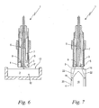
- Fig. 1 to 7 show in longitudinal section an embodiment of a ring piercer 1 according to the invention as phase images of various steps of the method according to the invention for the volumetric dosing of powder 2.
- Fig. 1 to 7 are the same features provided with the same reference numerals.
- the ring piercer 1 is constructed so as to be rotationally symmetrical with respect to a longitudinal axis which, during operation, is vertical, that is to say parallel to the direction of the weight force.
- the ring piercer 1 has a radially inner, approximately cylindrical core 6, which is formed by a tubular core sleeve 7 and a coaxially guided therein, sealingly applied to the inner wall of the core sleeve 7 central piston 8.
- the central piston 8 is displaceable parallel to the longitudinal axis of the Ringstechhebers 1 relative to the core sleeve 7.
- a tubular, approximately cylindrical dosing sleeve 3 of the Ringstechhebers 1 encloses the core 6 with a radial distance.
- an annular metering piston 5 is arranged in the radial direction between the cylindrical inner wall of the metering sleeve 3 and the cylindrical outer wall of the core 6, in the radial direction between the cylindrical inner wall of the metering sleeve 3 and the cylindrical outer wall of the core 6, an annular metering piston 5 is arranged.
- the annular metering piston 5 encloses the outer surface of the core 6 and thereby sealingly abuts against it. Radially outward, the annular metering piston 5 bears sealingly against the inner surface of the metering sleeve 3.
- the annular metering piston 5 and the core 6 are relatively displaceable in the axial direction against each other. Furthermore, the metering piston 5 is displaceable on its own or together with the core 6 in the axial direction relative to the metering sle
- Fig. 2 shows the piercer 1 after execution of a first method step.
- the piercer 1 In a starting position, not shown, the piercer 1 is initially positioned above a storage container with a powder bed 12 of powder 2 at a distance from the upper surface 13 thereof. On this basis, the piercer 1 is immersed in the powder 2 of the powder bed 12.
- the metering piston 5 and the central piston 8 each have a powder bed 12 facing end face 16, 17.
- the end face 16 of the annular metering piston 5 is in the position after Fig. 2 together with free end edges of the dosing sleeve 3 and the core sleeve 7 in a common plane.
- the end face 16 of the metering piston 5 including the free end edges of the metering sleeve 3 and the core sleeve 7 are brought into contact with the surface 13 of the powder bed 12. Subsequent to making contact with the surface 13, the end face 16, together with the free end edges of the dosing sleeve 3 and the core sleeve 7, is immersed in the powder bed 12 by a precompacting stroke ⁇ H 1 from the surface 13.
- the end face 17 of the central piston 8 is retracted during immersion or during the immersion of the metering piston 5 at least by the precompacting .DELTA.H 1 relative to the end face 16 of the metering piston 5. Im shown diarysbespiel it is slightly further withdrawn, so that a contact of the end face 17 with the surface 13 of the powder bed 12 and an associated precompacting of the powder 2 in the region of the central piston 5 does not take place.
- the metering sleeve 3 has a free, circumferential edge 9, which faces the powder bed 12 and which is designed as a circumferential cutting edge 10 with a one-sided, likewise circumferential outer inclined surface 11 ( Fig. 3 ).
- the inner surface of the dosing sleeve 3 is designed in the axial direction continuously to the cutting edge 10 cylindrical with constant radius, so that an axial relative movement of the metering piston 5 and the metering sleeve 3 against each other while maintaining their sealing abutment starting from the edge 9 and the cutting edge 10 to a Piston stroke H can be performed.
- the core sleeve 7 and the outer side sealingly fitting inner surface of the annular Dosierkolbens 5 are executed in the axial direction continuously to the end face 16 of the metering 5 or to the free edge of the core sleeve 7 cylindrical with a constant radius ,
- the sealing contact of the inside of the metering piston 5 on the outside of the core sleeve 7 is maintained over the entire piston stroke H.
- Fig. 3 is the outer metering 3 of the Ringstechhebers 1 in a next step, starting from the position to Fig. 2 lowered relative to the end face 16 by the piston stroke H in the powder bed 12 into it.
- the through the dosing sleeve 3 and the end face 16 limited space filled with the powder 2.
- the edge 9 of the dosing sleeve 3 in this case has a small distance to the bottom of the powder bed 12 though.
- the cutting edge 10 allows a virtually resistance-free penetration of the dosing sleeve 3 in the powder 2.
- the outwardly inclined inclined surface 11 pushes the powder 2 in the extent of the displacement volume of the dipped dosing 3 radially outward aside, without making such a displacement radially inward.
- the step after Fig. 3 have the positions of the metering piston 5, the core sleeve 7 and the central piston 8 relative to the surface 13 in comparison to the arrangement after Fig. 2 not changed.
- FIG. 4 Shown: Starting from the position to Fig. 3 Next, at least a portion of the core 6, namely in the embodiment shown, the core sleeve 7 immersed by the extent of the piston stroke H in the powder 2 of the powder bed 12. Following this, the circumferential free edge of the core sleeve 7 and the peripheral edge 9 of the dosing sleeve 3 is at the same axial height.
- a circumferentially annular metering chamber 4 is formed radially outwardly through the wall of the dosing sleeve 3, radially inwardly through the wall of the core sleeve 7 and axially upwardly through the end face 16 of Dosierkolbens 5 is limited. Since the movements after the Figures 3 and 4 take place within the precompacted powder 2, the metering chamber 4 is completely filled with precompacted and therefore homogenized in terms of its density powder 2.
- the central piston 8 In order to allow a displacement of a correspondingly small volume of powder without compression of the powder 2 into the interior 14, the central piston 8 at the latest when immersing the core sleeve 7, So at the same time or before, withdrawn by a discharge stroke h relative to the surface 13 of the powder bed 12. Without unwanted compression effect, the level of the powder 2 in the interior 14 of the core sleeve 7 may increase when they are immersed.
- Fig. 3 and 4 can also be a reverse order of magnitude appropriate, therefore, first the core sleeve 7 and only then the dosing sleeve 3 is lowered. A simultaneous lowering of both sleeves is possible.
- a further advantageous option is to move the metering sleeve 3 and / or the core sleeve 7 relative to the metering piston 5 about the piston stroke H before touching the ring piercer 1 with the powder bed 12. In this case, the dosing sleeve 3 and / or the core sleeve 7 is then subsequently immersed in the powder 2 of the powder bed 12 when the dosing piston 5 is withdrawn.
- Fig. 5 shows the above arrangement in a further process step: following the process step Fig. 4 is the dosing 5 before lifting the Ringstechhebers 1 from the powder bed 12 ( Fig. 5 ) by a Kompakt istshub .DELTA.H 2 down, that is lowered in the direction of the edge 9.
- the remaining components of the ring piercer 1 maintain their position, so that the volume of the metering chamber 4 is reduced.
- the edge 9 is in close proximity to the bottom of the powder bed 12, no powder 2 is ejected from the metering chamber 4. Rather, the powder 2 contained therein is reduced while its mass remains constant in its volume, so compacted.
- the Ring piercer 1 vibrated relative to the powder bed 12 in a direction transverse to the stroke direction, indicated by a double arrow 15 shearing movement or moved in any other way.
- the amount of powder 2 held in the metering chamber 4 is separated from the remaining powder 2 of the powder bed 12 in the plane defined by the edge 9.
- the subsequent process step is in Fig. 6 shown.
- the Ringstechheber 1 is starting from the position to Fig. 5 lifted in the axial direction of the powder bed 12, wherein compacted powder 2 remains in the metering chamber 4 and this completely fills.
- an annular powder body of powder 2 is transported, whose contour corresponds exactly to the contour of the metering chamber 4.
- the ring piercer 1 is moved to a container 20, which is schematically shown in FIG Fig. 7 is shown.
- the container 20 has radially inside a mandrel 19.
- this amount of powder has the shape of an annular body, it is annularly ejected according to arrows 22 in the annular space 18 of the container 20.
- the ring shape of the metering chamber 4 (FIG. Fig. 6 ) is adapted to the ring shape of the annular space 18 in the container 20; In the illustrated embodiment, both are annular. But it may also be appropriate, such as elliptical or oval shapes appropriate.
Landscapes
- Engineering & Computer Science (AREA)
- Quality & Reliability (AREA)
- Mechanical Engineering (AREA)
- Containers And Packaging Bodies Having A Special Means To Remove Contents (AREA)
- Feeding, Discharge, Calcimining, Fusing, And Gas-Generation Devices (AREA)
Priority Applications (2)
| Application Number | Priority Date | Filing Date | Title |
|---|---|---|---|
| DE200750003087 DE502007003087D1 (de) | 2007-07-27 | 2007-07-27 | Stechheber und Verfahren zum volumetrischen Dosieren von Pulver |
| EP20070014754 EP2019041B1 (fr) | 2007-07-27 | 2007-07-27 | Dispositif de dosage et procédé destiné au dosage volumétrique de poudre |
Applications Claiming Priority (1)
| Application Number | Priority Date | Filing Date | Title |
|---|---|---|---|
| EP20070014754 EP2019041B1 (fr) | 2007-07-27 | 2007-07-27 | Dispositif de dosage et procédé destiné au dosage volumétrique de poudre |
Publications (2)
| Publication Number | Publication Date |
|---|---|
| EP2019041A1 true EP2019041A1 (fr) | 2009-01-28 |
| EP2019041B1 EP2019041B1 (fr) | 2010-03-10 |
Family
ID=38871534
Family Applications (1)
| Application Number | Title | Priority Date | Filing Date |
|---|---|---|---|
| EP20070014754 Ceased EP2019041B1 (fr) | 2007-07-27 | 2007-07-27 | Dispositif de dosage et procédé destiné au dosage volumétrique de poudre |
Country Status (2)
| Country | Link |
|---|---|
| EP (1) | EP2019041B1 (fr) |
| DE (1) | DE502007003087D1 (fr) |
Cited By (1)
| Publication number | Priority date | Publication date | Assignee | Title |
|---|---|---|---|---|
| WO2015043748A1 (fr) * | 2013-09-25 | 2015-04-02 | Harro Höfliger Verpackungsmaschinen GmbH | Dispositif de dosage |
Citations (1)
| Publication number | Priority date | Publication date | Assignee | Title |
|---|---|---|---|---|
| WO2001096181A1 (fr) * | 2000-06-10 | 2001-12-20 | Glaxo Group Limited | Procede et appareil de transfert d'une quantite definie de poudre |
-
2007
- 2007-07-27 DE DE200750003087 patent/DE502007003087D1/de active Active
- 2007-07-27 EP EP20070014754 patent/EP2019041B1/fr not_active Ceased
Patent Citations (1)
| Publication number | Priority date | Publication date | Assignee | Title |
|---|---|---|---|---|
| WO2001096181A1 (fr) * | 2000-06-10 | 2001-12-20 | Glaxo Group Limited | Procede et appareil de transfert d'une quantite definie de poudre |
Cited By (1)
| Publication number | Priority date | Publication date | Assignee | Title |
|---|---|---|---|---|
| WO2015043748A1 (fr) * | 2013-09-25 | 2015-04-02 | Harro Höfliger Verpackungsmaschinen GmbH | Dispositif de dosage |
Also Published As
| Publication number | Publication date |
|---|---|
| EP2019041B1 (fr) | 2010-03-10 |
| DE502007003087D1 (de) | 2010-04-22 |
Similar Documents
| Publication | Publication Date | Title |
|---|---|---|
| EP3773802B1 (fr) | Dispositif d'application d'un fluide | |
| EP3773804B1 (fr) | Dispositif d'application d'un fluide | |
| EP3773803B1 (fr) | Dispositif d'application d'un fluide | |
| WO2019185605A1 (fr) | Dispositif d'application d'un fluide | |
| DE102011085283B4 (de) | Vorrichtung zum Dosieren von pulverförmigem Füllgut | |
| WO2010051826A1 (fr) | Dispositif et procédé de dosage de tabac en portions convenant pour le conditionnement | |
| EP2996943B1 (fr) | Pipette pour le dosage volumétrique de poudre | |
| DE2050885C3 (de) | Verfahren zur Dosierung von pulverformigen Stoffen mit Hilfe eines Stechheberdosiergeräts | |
| WO2016009248A2 (fr) | Procédé de fabrication d'une pièce moulée | |
| DE2944938C2 (de) | Arbeitsverfahren für eine kontinuierlich arbeitende Kapselfüll- und Verschließmaschine sowie eine Vorrichtung zum Durchführen des Verfahrens | |
| CH710350A2 (de) | Dosiervorrichtung. | |
| DE4318512C2 (de) | Verfahren und Vorrichtung zum Extrudieren von pulverförmigem Material | |
| DE3514512C1 (de) | Vorrichtung zum Verdichten und Verpacken pulverfoermiger,lufthaltiger Stoffe | |
| DE102015122147B4 (de) | Füll-Verfahren für Pulver und hierzu geeignete Vorrichtung | |
| DE2628390C2 (de) | Verfahren und Vorrichtung zum Herstellen eines oder mehrerer hohler Sandkerne für Gießformen | |
| EP2019041B1 (fr) | Dispositif de dosage et procédé destiné au dosage volumétrique de poudre | |
| EP3369409B1 (fr) | Dispositif et procédé de dosage de matériaux de remplissage pulvérulents | |
| DE2323933A1 (de) | Vorrichtung und verfahren zum verdichten trockenen pulvers | |
| EP3411673B1 (fr) | Éprouvette pour dosage | |
| DE10046127A1 (de) | Verfahren zum Verfüllen von mikroisiertem Pulver und Vorrichtung zum Durchführen des Verfahrens | |
| DE1541350B1 (de) | Vorrichtung zum Einfuehren eines Verschlusskolbens in eine mit Fluessigkeit gefuellte Spritzampulle | |
| DE2144071A1 (de) | Vorrichtung zur Herstellung von Presslingen aus einem pulverförmigen Material | |
| DE10046127A9 (de) | Verfahren zum verfuellen von mikroisiertem pulver und vorrichtung zum durchfuehren des verfahrens | |
| DE2554984C3 (de) | Verfahren und Vorrichtung zur Herstellung von Betonformlingen | |
| DE10246659A1 (de) | Verfahren und Vorrichtung zum dosierten Befüllen von Behältnissen mit mikronisiertem Pulver |
Legal Events
| Date | Code | Title | Description |
|---|---|---|---|
| PUAI | Public reference made under article 153(3) epc to a published international application that has entered the european phase |
Free format text: ORIGINAL CODE: 0009012 |
|
| AK | Designated contracting states |
Kind code of ref document: A1 Designated state(s): AT BE BG CH CY CZ DE DK EE ES FI FR GB GR HU IE IS IT LI LT LU LV MC MT NL PL PT RO SE SI SK TR |
|
| AX | Request for extension of the european patent |
Extension state: AL BA HR MK RS |
|
| 17P | Request for examination filed |
Effective date: 20090617 |
|
| GRAP | Despatch of communication of intention to grant a patent |
Free format text: ORIGINAL CODE: EPIDOSNIGR1 |
|
| AKX | Designation fees paid |
Designated state(s): DE GB IT |
|
| GRAS | Grant fee paid |
Free format text: ORIGINAL CODE: EPIDOSNIGR3 |
|
| GRAA | (expected) grant |
Free format text: ORIGINAL CODE: 0009210 |
|
| RIN1 | Information on inventor provided before grant (corrected) |
Inventor name: KARLHEINZ, SEYFANG Inventor name: SIEGFRIED, WEBER Inventor name: ACHIM, WOLF |
|
| AK | Designated contracting states |
Kind code of ref document: B1 Designated state(s): DE GB IT |
|
| REG | Reference to a national code |
Ref country code: GB Ref legal event code: FG4D Free format text: NOT ENGLISH |
|
| REF | Corresponds to: |
Ref document number: 502007003087 Country of ref document: DE Date of ref document: 20100422 Kind code of ref document: P |
|
| PLBE | No opposition filed within time limit |
Free format text: ORIGINAL CODE: 0009261 |
|
| STAA | Information on the status of an ep patent application or granted ep patent |
Free format text: STATUS: NO OPPOSITION FILED WITHIN TIME LIMIT |
|
| 26N | No opposition filed |
Effective date: 20101213 |
|
| PGFP | Annual fee paid to national office [announced via postgrant information from national office to epo] |
Ref country code: IT Payment date: 20180724 Year of fee payment: 12 Ref country code: DE Payment date: 20180723 Year of fee payment: 12 |
|
| PGFP | Annual fee paid to national office [announced via postgrant information from national office to epo] |
Ref country code: GB Payment date: 20180719 Year of fee payment: 12 |
|
| REG | Reference to a national code |
Ref country code: DE Ref legal event code: R119 Ref document number: 502007003087 Country of ref document: DE |
|
| GBPC | Gb: european patent ceased through non-payment of renewal fee |
Effective date: 20190727 |
|
| PG25 | Lapsed in a contracting state [announced via postgrant information from national office to epo] |
Ref country code: GB Free format text: LAPSE BECAUSE OF NON-PAYMENT OF DUE FEES Effective date: 20190727 Ref country code: DE Free format text: LAPSE BECAUSE OF NON-PAYMENT OF DUE FEES Effective date: 20200201 |
|
| PG25 | Lapsed in a contracting state [announced via postgrant information from national office to epo] |
Ref country code: IT Free format text: LAPSE BECAUSE OF NON-PAYMENT OF DUE FEES Effective date: 20190727 |