EP3773802B1 - Dispositif d'application d'un fluide - Google Patents
Dispositif d'application d'un fluide Download PDFInfo
- Publication number
- EP3773802B1 EP3773802B1 EP19714178.1A EP19714178A EP3773802B1 EP 3773802 B1 EP3773802 B1 EP 3773802B1 EP 19714178 A EP19714178 A EP 19714178A EP 3773802 B1 EP3773802 B1 EP 3773802B1
- Authority
- EP
- European Patent Office
- Prior art keywords
- roller
- receiving block
- piston
- cylinder
- plateau
- Prior art date
- Legal status (The legal status is an assumption and is not a legal conclusion. Google has not performed a legal analysis and makes no representation as to the accuracy of the status listed.)
- Active
Links
Images


Classifications
-
- A—HUMAN NECESSITIES
- A61—MEDICAL OR VETERINARY SCIENCE; HYGIENE
- A61M—DEVICES FOR INTRODUCING MEDIA INTO, OR ONTO, THE BODY; DEVICES FOR TRANSDUCING BODY MEDIA OR FOR TAKING MEDIA FROM THE BODY; DEVICES FOR PRODUCING OR ENDING SLEEP OR STUPOR
- A61M5/00—Devices for bringing media into the body in a subcutaneous, intra-vascular or intramuscular way; Accessories therefor, e.g. filling or cleaning devices, arm-rests
- A61M5/178—Syringes
- A61M5/20—Automatic syringes, e.g. with automatically actuated piston rod, with automatic needle injection, filling automatically
- A61M5/204—Automatic syringes, e.g. with automatically actuated piston rod, with automatic needle injection, filling automatically connected to external reservoirs for multiple refilling
-
- A—HUMAN NECESSITIES
- A61—MEDICAL OR VETERINARY SCIENCE; HYGIENE
- A61M—DEVICES FOR INTRODUCING MEDIA INTO, OR ONTO, THE BODY; DEVICES FOR TRANSDUCING BODY MEDIA OR FOR TAKING MEDIA FROM THE BODY; DEVICES FOR PRODUCING OR ENDING SLEEP OR STUPOR
- A61M5/00—Devices for bringing media into the body in a subcutaneous, intra-vascular or intramuscular way; Accessories therefor, e.g. filling or cleaning devices, arm-rests
- A61M5/178—Syringes
- A61M5/31—Details
- A61M5/315—Pistons; Piston-rods; Guiding, blocking or restricting the movement of the rod or piston; Appliances on the rod for facilitating dosing ; Dosing mechanisms
- A61M5/31501—Means for blocking or restricting the movement of the rod or piston
-
- A—HUMAN NECESSITIES
- A61—MEDICAL OR VETERINARY SCIENCE; HYGIENE
- A61M—DEVICES FOR INTRODUCING MEDIA INTO, OR ONTO, THE BODY; DEVICES FOR TRANSDUCING BODY MEDIA OR FOR TAKING MEDIA FROM THE BODY; DEVICES FOR PRODUCING OR ENDING SLEEP OR STUPOR
- A61M5/00—Devices for bringing media into the body in a subcutaneous, intra-vascular or intramuscular way; Accessories therefor, e.g. filling or cleaning devices, arm-rests
- A61M5/178—Syringes
- A61M5/30—Syringes for injection by jet action, without needle, e.g. for use with replaceable ampoules or carpules
-
- A—HUMAN NECESSITIES
- A61—MEDICAL OR VETERINARY SCIENCE; HYGIENE
- A61M—DEVICES FOR INTRODUCING MEDIA INTO, OR ONTO, THE BODY; DEVICES FOR TRANSDUCING BODY MEDIA OR FOR TAKING MEDIA FROM THE BODY; DEVICES FOR PRODUCING OR ENDING SLEEP OR STUPOR
- A61M5/00—Devices for bringing media into the body in a subcutaneous, intra-vascular or intramuscular way; Accessories therefor, e.g. filling or cleaning devices, arm-rests
- A61M5/178—Syringes
- A61M5/31—Details
- A61M5/3148—Means for causing or aiding aspiration or plunger retraction
-
- A—HUMAN NECESSITIES
- A61—MEDICAL OR VETERINARY SCIENCE; HYGIENE
- A61M—DEVICES FOR INTRODUCING MEDIA INTO, OR ONTO, THE BODY; DEVICES FOR TRANSDUCING BODY MEDIA OR FOR TAKING MEDIA FROM THE BODY; DEVICES FOR PRODUCING OR ENDING SLEEP OR STUPOR
- A61M5/00—Devices for bringing media into the body in a subcutaneous, intra-vascular or intramuscular way; Accessories therefor, e.g. filling or cleaning devices, arm-rests
- A61M5/178—Syringes
- A61M5/31—Details
- A61M5/315—Pistons; Piston-rods; Guiding, blocking or restricting the movement of the rod or piston; Appliances on the rod for facilitating dosing ; Dosing mechanisms
- A61M5/31511—Piston or piston-rod constructions, e.g. connection of piston with piston-rod
- A61M5/31513—Piston constructions to improve sealing or sliding
-
- A—HUMAN NECESSITIES
- A61—MEDICAL OR VETERINARY SCIENCE; HYGIENE
- A61M—DEVICES FOR INTRODUCING MEDIA INTO, OR ONTO, THE BODY; DEVICES FOR TRANSDUCING BODY MEDIA OR FOR TAKING MEDIA FROM THE BODY; DEVICES FOR PRODUCING OR ENDING SLEEP OR STUPOR
- A61M5/00—Devices for bringing media into the body in a subcutaneous, intra-vascular or intramuscular way; Accessories therefor, e.g. filling or cleaning devices, arm-rests
- A61M5/178—Syringes
- A61M5/31—Details
- A61M5/315—Pistons; Piston-rods; Guiding, blocking or restricting the movement of the rod or piston; Appliances on the rod for facilitating dosing ; Dosing mechanisms
- A61M5/31525—Dosing
- A61M5/31528—Dosing by means of rotational movements, e.g. screw-thread mechanisms
-
- A—HUMAN NECESSITIES
- A61—MEDICAL OR VETERINARY SCIENCE; HYGIENE
- A61M—DEVICES FOR INTRODUCING MEDIA INTO, OR ONTO, THE BODY; DEVICES FOR TRANSDUCING BODY MEDIA OR FOR TAKING MEDIA FROM THE BODY; DEVICES FOR PRODUCING OR ENDING SLEEP OR STUPOR
- A61M5/00—Devices for bringing media into the body in a subcutaneous, intra-vascular or intramuscular way; Accessories therefor, e.g. filling or cleaning devices, arm-rests
- A61M5/178—Syringes
- A61M5/31—Details
- A61M5/315—Pistons; Piston-rods; Guiding, blocking or restricting the movement of the rod or piston; Appliances on the rod for facilitating dosing ; Dosing mechanisms
- A61M5/31565—Administration mechanisms, i.e. constructional features, modes of administering a dose
- A61M5/31576—Constructional features or modes of drive mechanisms for piston rods
-
- A—HUMAN NECESSITIES
- A61—MEDICAL OR VETERINARY SCIENCE; HYGIENE
- A61M—DEVICES FOR INTRODUCING MEDIA INTO, OR ONTO, THE BODY; DEVICES FOR TRANSDUCING BODY MEDIA OR FOR TAKING MEDIA FROM THE BODY; DEVICES FOR PRODUCING OR ENDING SLEEP OR STUPOR
- A61M5/00—Devices for bringing media into the body in a subcutaneous, intra-vascular or intramuscular way; Accessories therefor, e.g. filling or cleaning devices, arm-rests
- A61M5/178—Syringes
- A61M5/20—Automatic syringes, e.g. with automatically actuated piston rod, with automatic needle injection, filling automatically
- A61M2005/2006—Having specific accessories
- A61M2005/202—Having specific accessories cocking means, e.g. to bias the main drive spring of an injector
-
- A—HUMAN NECESSITIES
- A61—MEDICAL OR VETERINARY SCIENCE; HYGIENE
- A61M—DEVICES FOR INTRODUCING MEDIA INTO, OR ONTO, THE BODY; DEVICES FOR TRANSDUCING BODY MEDIA OR FOR TAKING MEDIA FROM THE BODY; DEVICES FOR PRODUCING OR ENDING SLEEP OR STUPOR
- A61M5/00—Devices for bringing media into the body in a subcutaneous, intra-vascular or intramuscular way; Accessories therefor, e.g. filling or cleaning devices, arm-rests
- A61M5/178—Syringes
- A61M5/31—Details
- A61M2005/3114—Filling or refilling
-
- A—HUMAN NECESSITIES
- A61—MEDICAL OR VETERINARY SCIENCE; HYGIENE
- A61M—DEVICES FOR INTRODUCING MEDIA INTO, OR ONTO, THE BODY; DEVICES FOR TRANSDUCING BODY MEDIA OR FOR TAKING MEDIA FROM THE BODY; DEVICES FOR PRODUCING OR ENDING SLEEP OR STUPOR
- A61M5/00—Devices for bringing media into the body in a subcutaneous, intra-vascular or intramuscular way; Accessories therefor, e.g. filling or cleaning devices, arm-rests
- A61M5/178—Syringes
- A61M5/31—Details
- A61M2005/3128—Incorporating one-way valves, e.g. pressure-relief or non-return valves
Definitions
- the present invention relates to a device for applying a fluid, which can be designed, for example, as a needle-free self-filling syringe with which a liquid medicament can be administered to animals.
- Such devices for applying a fluid should be as light as possible, have a long service life and be associated with low maintenance costs and effort.
- the object of the invention is to provide a device for applying a fluid which realizes at least one of the properties mentioned.
- the device according to the invention for applying a fluid comprises a cylinder which has an open dispensing end, a piston which can be displaced in the cylinder between a front and a rear end position and which is connected to a piston rod which extends along a first direction via a rear end opposite the open dispensing end of the cylinder protrudes and is guided in a receiving block, a non-return valve (or suction valve) closing the open discharge end and a clamping device connected to the piston rod, which is arranged in the receiving block.
- the clamping device can move the piston rod in a clamping process, when the piston is in its front end position, along the first direction until the piston is in its rear end position in order to fill the cylinder with the fluid to be applied and the piston rod to the open dispensing end to pretension. Furthermore, when the piston is in its rear end position, the clamping device can release the piston rod in a dispensing process, so that the piston moves against the first direction due to the applied preload up to its front end position and the fluid in the cylinder via the check valve for application is delivered.
- the cylinder, together with the check valve is designed as an exchangeable front group, which can also be referred to as an exchangeable group, which is detachably connected to the receiving block.
- the entire front group which is subject to the greatest wear during operation of the device for applying a fluid (preferably a liquid), can thus easily be exchanged for a new (preferably structurally identical) front group which is then connected to the receiving block. This significantly increases the durability of the entire device for applying a fluid.
- a fluid preferably a liquid
- the exchangeable group can be arranged at the front end of the device according to the invention.
- part of the exchangeable group can be in contact with the animal to which the fluid is to be applied when the device according to the invention is used as intended.
- at least this part of the interchangeable group protrudes from the rest of the device according to the invention.
- the interchangeable group can have a part which forms the distal end of the device according to the invention, so that for this reason, for example, the interchangeable group can also be referred to as an interchangeable front group.
- An exchangeable front group is understood here in particular to mean that the front group as a whole can be separated from the receiving block and replaced by a structurally identical front group which is connected to the receiving block for exchange.
- the front group, which is separated from the mounting block can be serviced (e.g. by replacing wear parts such as seals) and then reconnected to the mounting block.
- the releasable connection between the front group and the receiving block can in particular be a screw connection.
- any other type of detachable connection such as a bayonet connection, is also possible.
- the application device has a nozzle for the needleless application of the
- Fluids which is connected to the open discharge end of the cylinder via the check valve and which is part of the front group. This makes it possible to also exchange the nozzle when replacing the front group.
- the device can have a needle or cannula which is connected to the open dispensing end of the cylinder via the check valve and which is part of the front group.
- the needle and the cannula can in turn be interchangeable.
- the application device according to the invention can have exactly one cylinder with exactly one piston rod and exactly one front group.
- the application device has two or more cylinders with two or more piston rods and two or more front groups, which are all designed the same, so that two or more identical or different fluids can be acted upon at the same time.
- the individual cylinders can have the same or different volumes.
- the application device according to the invention is designed in particular as a self-filling application device which uses the clamping process to fill the cylinder with the fluid to be applied (e.g. a liquid to be applied).
- the fluid to be applied e.g. a liquid to be applied
- the application device can be designed in such a way that a negative pressure is built up in the cylinder during the clamping process which, when the piston is in its rear end position, is used to suck the fluid into the cylinder due to the negative pressure.
- the piston can have in its distal end a blind bore extending in the longitudinal direction of the piston rod, from which one or more radial bores branch off, which establish a fluid connection to a reservoir of the fluid to be applied in the rear end position of the piston.
- the application device can have the motor which is used to carry out the clamping process. It can also be said that the motor provides the energy that is necessary to build up the preload of the piston rod.
- the motor can in particular be mounted on the receiving block.
- a battery and / or a rechargeable accumulator can be provided as an energy source for operating the motor and any other consumers.
- the energy source can be designed, for example, in the foot or as the foot of the application device. Furthermore, the energy source can be exchangeable or permanently installed.
- the tensioning device can have a spring which biases the piston rod towards the open dispensing end when the piston is in the rear end position.
- the application device can furthermore have a ramp which can be rotated by means of the motor and has a ramp path extending along a helical line.
- the ramp track can rise from a first plateau or level along an incline area to a second plateau or second level and drop from the second plateau via a jump flank to the first plateau.
- the ramp track thus has a single turn and can be referred to as helical with a step.
- the tensioning device can also have a roller contacting the ramp track, which is rotatably mounted in a driver that is connected to the end of the piston rod protruding from the cylinder, so that when the ramp rotates, the ramp track passes under the roller that rotates as a result.
- the roller is preferably mounted such that its axis of rotation is perpendicular to the first direction (or perpendicular to the longitudinal axis of the piston rod).
- the ramp track can be rotated starting from a contact of the roller with the first plateau so that the roller runs on the slope area up to the second plateau and thereby the piston is moved into its rear end position.
- the ramp track can be rotated starting from a contact of the roller with the second plateau until the roller hits the first plateau over the jump flank and the piston is thereby moved into its front end position.
- the distance of the second plateau from the first plateau along the axis of rotation of the ramp preferably corresponds to the distance from the front to the rear end position of the piston along the first direction and thus the piston stroke.
- the rotary movement of the motor is converted into a translational movement of the piston rod along its longitudinal axis.
- the application device can thus be tensioned by means of the motor, so that a user only has to actuate a trigger element, such as a button, a switch, a rocker switch or a button, in order to release the dispensing process and thus effect the application of the fluid.
- a trigger element such as a button, a switch, a rocker switch or a button
- the gradient region of the ramp track can have a first section adjoining the first plateau and a second section adjoining it, the gradient of the second section being greater than the gradient of the first section.
- the slope area of the ramp track can be designed so that both sections are linear with respect to the angle of rotation of the screw.
- the first section and / or the second section can have a non-linear profile in relation to the angle of rotation.
- the gradient of the respective section is preferably the mean gradient of the respective section.
- the non-linear course of the respective section is preferably a course in which the local slope increases as the angle of rotation increases.
- the non-linear course of the respective section can preferably be a concave course of curvature.
- the rotation angle range (or the rotation angle length) of the first section can be smaller than the rotation angle range (or the rotation angle length) of the second section.
- the ratio of the angle of rotation range of the first section to the angle of rotation range of the second section is preferably not more than 4/6 and not less than 1/9.
- the roller can have a support area that rests on the incline area of the ramp track and at least one laterally adjoining side area which has a smaller outer diameter than that of the support area and which does not lie on the incline area of the ramp track.
- both the support area and the side area can come into contact with an edge of the ramp track connecting the second plateau to the jump flank. This leads to the advantage that there is a relatively low rolling or frictional resistance between the roller and the ramp track in the area of the incline.
- both the receiving area and the side area then rest on the edge, so that the contact surface is enlarged here so that there is less pressure. This is advantageous because when the roller passes over the edge, the greatest force acts on the roller, and thus undesirable pressure peaks can be reduced. This increases the durability of the roller.
- the roller can each have a laterally adjoining side area with a smaller outer diameter than that of the support area on both sides of the support area. This leads to a further reduction in the pressure on the roller when it crosses the edge.
- the roller can be designed in such a way that the outer diameter of the support area is constant.
- the outer diameter of the respective side area can decrease in a direction towards the side of the roller (or in a direction away from the support area or as the distance from the support area increases).
- the roller can be designed as a plastic roller.
- the ramp can be made of metal.
- the receiving block can be designed as a one-piece receiving block which is produced by an additive manufacturing process.
- Such an additive manufacturing process can also be referred to as 3D printing and can be, for example, a laser sintering process.
- the receiving block can be manufactured with a relatively low weight and high rigidity and strength.
- the total weight of the application device is kept as low as possible, as a result of which comfortable, long-term operation is possible for a user.
- the one-piece design of the receiving block by means of the additive manufacturing process advantageously means that the receiving block can be made extremely compact, which is not possible with conventional machining manufacturing processes.
- a metal (or a metal alloy) and in particular titanium is preferably used as the material for the receiving block, so that the receiving block is made of metal (or a metal alloy) and in particular of titanium.
- aluminum, steel (e.g. maraging steel), stainless steel, titanium, a nickel alloy and / or a cobalt-chromium alloy can be used as the material for the receiving block.
- Other possible materials are AlSiMg alloys, CoCrMo alloys and nickel-chromium alloys. Materials that can be welded can also be used. All of these materials can be present in a form (e.g. as a powder) in order to be able to produce the receiving block from them by means of an additive manufacturing process (and in particular by means of laser sintering).
- the receptacle block can have a motor bearing, a guide cylinder for the piston rod, at least one receptacle for a control board, a receptacle for a fluid connection for a fluid container and / or at least one housing fixing point which is / are formed in one piece with the receptacle block.
- the piston can be formed in one piece with the piston rod.
- the front end of the piston rod forms the piston.
- the piston is a separate element that is connected to the piston rod.
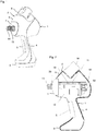
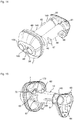
- the in Fig. 1 The embodiment shown comprises the device 1 according to the invention for applying a fluid (for example a liquid) a housing 2, which has a foot 3, which is used as a
- Stand 3 can be formed, comprises a grip section 4 for holding the device 1, a trigger 5 arranged in the grip section 4 for actuating the device 1, a head area 6 with a delivery area 7 and a receptacle 8 in the upper end of the head area 6.
- the device 1 according to the invention which can also be referred to as the application device 1, is designed in the exemplary embodiment described here for the simultaneous application of two different drugs to animals, the application of the drugs being carried out without a needle through the skin.
- a separate cylinder-piston arrangement is provided for each drug, as will be described in detail below, which is designed as a self-filling type in such a way that moving the piston towards the dispensing end causes the fluid to be ejected and a opposite movement of the piston causes a filling of the cylinder for the next injection process.
- the application device 1 comprises a receiving block 10, which carries a control circuit board 11 and a motor 12, as well as two front groups 13, 14, one of which is shown in FIG Fig. 2 only the front group 13 is visible. Since the front groups 13 and 14 are structurally identical, essentially only the front group 13 is described in detail below.
- a medicament container M which contains a liquid medicament for the front group 13, is shown schematically in the receptacle 8.
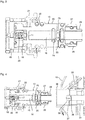
- FIG Fig. 3 A sectional view of the front group 13 is shown in FIG Fig. 3 shown.
- the front group 13 comprises an insert 15 in which a syringe cylinder 16 with an open dispensing end 17 is formed.
- a check valve 18 (or a suction valve 18) is arranged on the outlet side.
- the check valve 18 When the check valve 18 is open, the open dispensing end 17 opens into a nozzle 19 through which the fluid to be dispensed (here the corresponding liquid medicament) is dispensed.
- the check valve 18 is biased by a spring 20 towards the open delivery end 17 and closes the open delivery end 17 at the in Fig. 3 position of the check valve 18 shown.
- the front group 13 comprises a release cage 21 which extends over the nozzle 19 and which is pressed and pretensioned by means of a spring 22 in the direction from the open discharge end 17 towards the nozzle 19.
- the release cage 21 is along the longitudinal axis of the front group 13 (from left to right in Fig. 3 ) displaceably mounted so that when the application device 1 is applied to the corresponding skin area on the animal, it is displaced in the direction from the nozzle 19 to the open dispensing end 17 and, for example, triggers a contact sensor (not shown) that enables the application process to be triggered, such as will be described in detail below.
- the insert 15 has radially running feed channels 25 via which the fluid to be applied or the liquid medicament reaches the syringe cylinder 16 for the next injection process.
- a guide bush 28 is arranged so that the front group 13 can be inserted into a distal end 30 of the receiving block 10 ( Fig. 4 ) can be screwed in, since an internal thread 31 for the external thread 27 of the front group 13 is provided in the distal end 30.
- Fig. 4 shows the front group 13 and the distal end 30 of the receiving block 10 before the screwing-in process.
- the two elements 13, 30 are screwed together so that a piston rod 35 guided in the receiving block 10 with a piston 36 formed at its distal end protrudes slightly into the syringe cylinder 16 and the piston rod 35 is guided through the guide bushing 28.
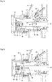
- the piston rod 35 can, as will be described in detail below, of the in Fig. 5 basic position shown (hereinafter also referred to as basic position) to the in Fig. 6
- the ejection or dispensing position shown (hereinafter also referred to as the ejection or dispensing position) can be moved in the direction of the open dispensing end 17 and from there back into the in Fig. 5 shown basic position.
- piston rod 35 If the piston rod 35 is in the basic position, its distal end and thus the piston 36 is in its rear end position ( Fig. 5 ). When the piston rod 35 is in the delivery position, the piston 36 is in its front end position ( Fig. 6 ).
- the syringe cylinder 16 When the piston rod 35 is in the in Fig. 5 is positioned, the syringe cylinder 16 is filled with the liquid medicament to be ejected. A movement of the piston rod 35 towards the open dispensing end 17 then causes the non-return valve 18 to open and the liquid is dispensed via the nozzle 19 as a jet which cuts so far into the skin of the animal that the drug passes through this cut into the Skin can be applied.
- the liquid medication is due to the negative pressure in the syringe cylinder 16 from the medication container M via the connection element 33, the chamber 32, the feed channel (s) 25, the transverse bore (s) 38 and the blind bore 37 in the syringe cylinder 16 sucked so that it is filled with the liquid medicine.
- the drug can be applied again during the next triggering process, with some of the liquid drug being pushed back into the chamber 32 via the supply channels 25 at the beginning of the movement of the piston rod 35 from the basic position to the ejection position.
- This pushing back is advantageous because the piston 36 or the piston rod 35 can be accelerated more easily, which leads to a higher pressure with which the remaining medicament in the syringe cylinder 16 is applied and which is desired for the needle-free injection described.
- the front group 13 which in particular comprises the syringe cylinder 16, the check valve 18 and the nozzle 19, is designed to be exchangeable as a whole. By means of its external thread 27, it can be screwed into the corresponding internal thread 31, which is formed on the distal end 30 of the receiving block 10, and screwed out again.
- a worn front group 13 can thus easily be exchanged for a new, structurally identical front group 13. This advantageously means that the application device 1 can be used for a longer period overall, since the components of the application device 1 that are most susceptible to wear can easily be exchanged.
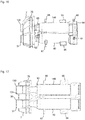
- the receiving block 10 has a first receiving cylinder 40, into which the piston rod 35 for the first front group 13 is guided, and a second receiving cylinder 140, in which a piston rod 135 for the second front group 14 is guided. Since the structure of the two cylinder-piston arrangements and thus also of the two receiving cylinders 40, 140 is the same, essentially only the first cylinder-piston arrangement with the first receiving cylinder 40 is described below in the description of the receiving block 10. Corresponding elements in the second receiving cylinder 140 are denoted by reference symbols which are 100 larger than in the elements of the first receiving cylinder 40, but will not be described again.
- the piston rod 35 extends through the first receiving cylinder 40, in which a spring 41 for moving the piston rod 35 from the in Fig. 5 tense basic position shown in Fig. 6 Ejection position shown is included.
- a distal end 42 of the spring 41 rests against a stop section 43 of the piston rod 35.
- the proximal end 44 of the spring 41 rests against a guide bushing 45 which is screwed into the proximal end of the first receiving cylinder 40, so that when the piston rod moves from the in Fig. 6 ejection positions shown along the first direction to the in Fig. 5
- the spring 41 is compressed and thereby biased, as shown in FIG Fig. 9 is shown.
- the end of the piston rod 35 protruding proximally from the receiving cylinder 40 is connected to a driver 50 which has a rotatably mounted roller 51, the axis of rotation of the roller 51 extending essentially perpendicular to the longitudinal axis of the piston rod 35.
- a modification of the application device 1 according to the invention is shown.
- the driver 50 is connected to the proximal end of the piston rod 35 and the proximal end of a guide rod 39, which is slidably mounted in the receiving block 10.
- the roller 51 runs on a ramp 52 which rotates under the roller 51 and which is rotated by the motor 12 about an axis parallel to the longitudinal axis of the piston rod 35.
- a battery and / or a rechargeable accumulator can be provided as the power supply for the motor.
- the battery and / or the accumulator can be arranged, for example, in the foot 3 or as the foot 3 of the application device 1.
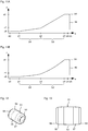
- the ramp 52 has a ramp path 53 which runs along a helical line with a single turn, such as in particular Fig. 7, 8 and 10 can be found.
- the second slope is present up to the angle of rotation ⁇ 3 and then changes to a second plateau in which no increase (or only a very small increase or only a very small decrease) in the pitch z2 with a further increase in the angle of rotation up to the angle of rotation a4 of less than 360 °.
- an edge 54 is formed due to the jump flank 46 which connects the second plateau to the first plateau.
- the piston rod 35 is in its tensioned basic position according to FIG Fig. 5 .
- the application device 1 is thus ready for the application of the liquid medicament.
- the motor 12 continues to rotate the ramp 52, so that when the angle of rotation ⁇ 5 is exceeded, the roller 51 runs over the edge 54 and, due to the spring tension of the spring 41, suddenly drops from the pitch z2 falls back to the pitch z0 of the first plateau, so that the fluid present in the syringe cylinder 16 is ejected in the manner described.
- the motor 12 then rotates the ramp 52 further up to the second plateau and stops the rotary movement here, so that the syringe cylinder 16 is again filled with the liquid medicament is filled and the piston rod 35 is brought back into its tensioned basic position.
- the application device 1 is thus ready for a further application process. In this way, the application device 1 can be repeatedly drawn up and released.
- the two slope sections S1 and S2 form a slope area that runs from the first plateau to the second plateau.
- the two incline sections S1 and S2 do not have to run linearly in relation to the angle of rotation. You can also, as exemplified in Figure 11B is shown, have a concave curvature (in which the local slope increases with increasing angle of rotation). However, in this case too, the mean slope of the first slope section S1 is smaller than the mean slope of the second slope section S2.
- tensioning device S The combination of motor 12, ramp 52, driver 50 with roller 51, spring 41, 141 and guide bush 45, 145 can be referred to as a tensioning device S.
- the roller 51 comprises a central region 55 which has a constant outer diameter. This is followed on each side by a side area 56, 57 in which the outer diameter decreases towards the side.
- Both side areas 56 and 57 are each adjoined by an end area 58, 59 which is rounded so that the roller 51 does not have any edges.
- the central area 55 rests on the ramp path 53 in the angle of rotation range from ⁇ 1 to ⁇ 3 (in particular from ⁇ 0 to ⁇ 5), whereas the side areas 56 and 57 do not rest in this angle of rotation range, but only in contact with the edge 54 when it crosses the edge Ramp 53 come.
- the rolling resistance of the roller 51 when the piston rod 35 is tensioned can thus be as low as possible.
- the side regions 56 and 57 are also in contact with the edge 54, which advantageously increases the forces between the roller 51 and the edge 54 of the ramp track 52 over a larger support surface (middle area 55 and the two side areas 56, 57) so that there is less pressure. This increases the durability of the device 1 and in particular of the roller 51.
- This characteristic of the slope of the ramp path 52 advantageously leads to the durability of the motor 50 being increased.
- the receiving block 10 is formed in one piece.
- an additive manufacturing process was used here, such as laser sintering, selective laser sintering or direct metal laser sintering, with which finer and / or more complex structures can be produced compared to machining processes.
- the receiving block 10 can thus be provided with a relatively low weight and a high durability of the application device 1 can be ensured.
- the material for the receiving block 10 aluminum, steel (e.g. maraging steel), stainless steel, titanium, a nickel alloy and / or a cobalt-chromium alloy can be used as the material for the receiving block 10.
- the material for the laser sintering is preferably in the form of metal powder.
- a thin layer of the powder material can be applied to a building platform.
- a laser beam melts the powder exactly at the points that are specified by the computer-generated component design data of the receiving block 10.
- the construction platform is then lowered and another thin layer of the powder material is applied.
- the material is melted again and connects to the underlying layer at the defined points. These steps are repeated until the entire receiving block 10 is formed.
- the receiving block 10 comprises four board receiving points 60, 61, 62 and 63, onto which the board 11 can be placed and, for example, screwed to the receiving block 10.
- the receiving block further comprises an engine mount 64 for receiving and mounting the engine 12.
- fixation points 65, 66, 67 and 68 are formed for the outer housing 2 of the application device 1. Sections of corresponding receptacles 265, 266, 267 and 268 of the outer housing 2 are shown in FIG Figures 7 to 9 drawn.
- the umbrella-like delivery area 7 is provided, which in addition to the corresponding internal thread 31 and 131 for the first and second front group 13 and FIG. 14 also has receptacles 69 and 169 for the respective release sensor (not shown) which detects the position of the release cage 21, 121.
- an O-ring receptacle 70 is formed in the dispensing area 7, into which an O-ring 71 (e.g. Fig. 9 , 16 and 17 ) can be used to ensure a seal against the adjacent housing 2 in the installed state.
- an O-ring 71 e.g. Fig. 9 , 16 and 17
- the receiving block 10 comprises a receptacle 72, 172 for each receiving cylinder 40, 140, into which the corresponding connection element 33, 133, which can also be referred to as a fluid adapter, can be inserted.
- connection element 33, 133 is preferably produced by machining.
- Titanium is preferably used as the material for the receiving block 10. This material is on the one hand relatively light and on the other hand ensures the desired strength. Any other suitable material for additive manufacturing processes can of course be used.
- the previous description has assumed that two different drugs are to be applied at the same time.
- the application device 1 according to the invention can, however, also be designed in such a way that the receiving block 10 has only a single receiving cylinder 40, so that only a single medicament can also be applied during a triggering process.
- the second receiving cylinder 140 and the second cylinder-piston rod combination are then preferably omitted.
- the application device 1 is designed as a needleless application device 1.
- it can also be designed as an application device 1 with a needle or a cannula, so that in this case the needle or cannula has to be pierced into the skin of the animal and then the liquid drug is applied in the manner described.
Landscapes
- Health & Medical Sciences (AREA)
- Vascular Medicine (AREA)
- Engineering & Computer Science (AREA)
- Anesthesiology (AREA)
- Biomedical Technology (AREA)
- Heart & Thoracic Surgery (AREA)
- Hematology (AREA)
- Life Sciences & Earth Sciences (AREA)
- Animal Behavior & Ethology (AREA)
- General Health & Medical Sciences (AREA)
- Public Health (AREA)
- Veterinary Medicine (AREA)
- Infusion, Injection, And Reservoir Apparatuses (AREA)
- Reciprocating Pumps (AREA)
Claims (15)
- Dispositif pour l'application sans aiguille d'un fluide, pourvud'un cylindre (16, 116), qui présente une extrémité de distribution ouverte (17),d'un piston (36) pouvant coulisser dans le cylindre (16, 116) entre une position d'extrémité avant et une position d'extrémité arrière, qui est relié à une tige de piston (35), qui dépasse, le long d'une première direction, d'une extrémité arrière, opposée à l'extrémité de distribution ouverte (17), du cylindre (16, 116) et qui est guidée dans un bloc de réception (10) ,d'un clapet antiretour (18) fermant l'extrémité de distribution ouverte (17) etd'un dispositif de serrage (S) relié à la tige de piston (35, 135), qui est agencé dans le bloc de réception (10),le dispositif de serrage (S), lorsque le piston (36) se trouve dans sa position d'extrémité avant, pouvant déplacer la tige de piston (35, 135) dans un processus de serrage le long de la première direction jusqu'à ce que le piston (36) se trouve dans sa position d'extrémité arrière, afin de remplir ainsi le cylindre (16, 116) avec le fluide à appliquer et de précontraindre la tige de piston (35, 135) vers l'extrémité de distribution ouverte (17), etle dispositif de serrage (S), lorsque le piston (36) se trouve dans sa position d'extrémité arrière, pouvant libérer la tige de piston (35, 135) dans un processus de distribution, de telle sorte que le piston (36), en raison de la précontrainte appliquée, se déplace à l'encontre de la première direction jusqu'à sa position d'extrémité avant et le fluide dans le cylindre (16, 116) est alors distribué pour l'application par l'intermédiaire du clapet antiretour (18),le cylindre (16, 116) étant configuré conjointement avec le clapet antiretour (18) en tant que groupe frontal échangeable (13, 14), qui est relié de manière amovible au bloc de réception (10),et le dispositif comprenant une buse (19) pour l'application sans aiguille du fluide, qui est reliée à l'extrémité de distribution ouverte du cylindre (16, 116) par l'intermédiaire du clapet antiretour (18) et qui fait partie du groupe frontal (13, 14).
- Dispositif selon la revendication 1,
la liaison amovible entre le groupe frontal (13, 14) et le bloc de réception (10) étant une liaison à vis. - Dispositif selon l'une quelconque des revendications précédentes,
le dispositif de serrage (S) comprenant un ressort (41, 141), qui précontraint la tige de piston (35, 135) vers l'extrémité de distribution ouverte lorsque le piston (36) se trouve dans la position d'extrémité arrière. - Dispositif selon l'une quelconque des revendications précédentes,le dispositif de serrage (S) comprenant une rampe (52) rotative au moyen d'un moteur (12), munie d'une piste de rampe (53) s'étendant le long d'une hélice,la piste de rampe (53) montant à partir d'un premier plateau le long d'une zone de montée (S1, S2) jusqu'à un deuxième plateau et descendant à partir du deuxième plateau par l'intermédiaire d'un flanc abrupt (46) jusqu'au premier plateau,le dispositif de serrage (S) comprenant en outre un rouleau (51) en contact avec la piste de rampe (53), qui est monté de manière rotative dans un entraîneur (50), qui est relié à l'extrémité de la tige de piston (35, 135) dépassant du cylindre (16, 116), de telle sorte que lors d'une rotation de la rampe (52), la piste de rampe (53) passe sous le rouleau (51) qui tourne en conséquence,pour le processus de serrage, la piste de rampe (53) étant tournée à partir d'un contact du rouleau (51) avec le premier plateau de telle sorte que le rouleau (51) circule sur la zone de montée jusqu'au deuxième plateau et le piston (36) étant ainsi déplacé dans sa position d'extrémité arrière,pour le processus de distribution, la piste de rampe (53) étant tournée à partir d'un contact du rouleau (51) avec le deuxième plateau jusqu'à ce que le rouleau (51) tombe sur le premier plateau par l'intermédiaire du flanc abrupt (46) et le piston (36) étant ainsi déplacé dans sa position d'extrémité avant.
- Dispositif selon la revendication 4,
le moteur (12) étant monté dans le bloc de réception (10) . - Dispositif selon la revendication 4 ou 5,
la zone de montée de la piste de rampe (53) comprenant une première section (S1) raccordée au premier plateau et une deuxième section (S2) raccordée à celle-ci, la pente de la deuxième section (S2) étant plus grande que la pente de la première section (S1). - Dispositif selon la revendication 6,
les deux sections (S1, S2) s'étendant linéairement par rapport à l'angle de rotation de l'hélice. - Dispositif selon la revendication 5 ou 6, la longueur d'angle de rotation de la première section (S1) étant inférieure à la longueur d'angle de rotation de la deuxième section (S2).
- Dispositif selon l'une quelconque des revendications 4 à 8,le rouleau (51) comprenant une zone d'appui (55), qui s'appuie sur la zone de montée (S1, S2) de la piste de rampe (53), et au moins une zone latérale (56, 57) raccordée latéralement à celle-ci, qui présente un diamètre extérieur plus petit que la zone d'appui (55) et qui ne s'appuie pas sur la zone de montée (S1, S2) de la piste de rampe (53),lors du processus de distribution, aussi bien la zone d'appui (55) que la zone latérale (56, 57) venant en contact avec un bord (54) de la piste de rampe (53) reliant le deuxième plateau au flanc abrupt (46).
- Dispositif selon la revendication 9,
le rouleau (51) comprenant sur les deux côtés de la zone d'appui (55) une zone latérale (56, 57) raccordée latéralement, ayant un diamètre extérieur plus petit que celui de la zone d'appui (55). - Dispositif selon la revendication 9 ou 10,
le diamètre extérieur de la zone latérale respective (56, 57) diminuant dans une direction allant vers le côté du rouleau (51). - Dispositif selon l'une quelconque des revendications 4 à 11,
le rouleau (51) étant monté dans l'entraîneur (50) de telle sorte que son axe de rotation est perpendiculaire à la première direction. - Dispositif selon l'une quelconque des revendications précédentes,
le bloc de réception (10) étant configuré sous la forme d'un bloc de réception d'un seul tenant (10), qui est fabriqué par un procédé de fabrication additif. - Dispositif selon la revendication 13,
le bloc de réception (10) étant configuré sous la forme d'un bloc de réception métallique (10). - Dispositif selon la revendication 13 ou 14,
le bloc de réception (10) comprenant un palier de moteur (64), un cylindre de guidage (40, 140) pour la tige de piston (35, 135), au moins un logement (60, 61, 62, 63) pour une platine de commande (11), un logement (72, 172) pour un raccord de fluide (33) pour un contenant de fluide (M) et/ou au moins un emplacement de fixation de boîtier (65, 66, 67, 68), qui est/sont configuré(s) d'un seul tenant avec le bloc de réception (10) .
Applications Claiming Priority (2)
| Application Number | Priority Date | Filing Date | Title |
|---|---|---|---|
| DE102018107100.0A DE102018107100A1 (de) | 2018-03-26 | 2018-03-26 | Vorrichtung zum Applizieren eines Fluids |
| PCT/EP2019/057533 WO2019185602A1 (fr) | 2018-03-26 | 2019-03-26 | Dispositif d'application d'un fluide |
Publications (2)
| Publication Number | Publication Date |
|---|---|
| EP3773802A1 EP3773802A1 (fr) | 2021-02-17 |
| EP3773802B1 true EP3773802B1 (fr) | 2021-11-03 |
Family
ID=65955220
Family Applications (1)
| Application Number | Title | Priority Date | Filing Date |
|---|---|---|---|
| EP19714178.1A Active EP3773802B1 (fr) | 2018-03-26 | 2019-03-26 | Dispositif d'application d'un fluide |
Country Status (7)
| Country | Link |
|---|---|
| US (1) | US12285593B2 (fr) |
| EP (1) | EP3773802B1 (fr) |
| JP (3) | JP7536647B2 (fr) |
| CN (1) | CN111902172A (fr) |
| DE (1) | DE102018107100A1 (fr) |
| ES (1) | ES2899740T3 (fr) |
| WO (1) | WO2019185602A1 (fr) |
Families Citing this family (12)
| Publication number | Priority date | Publication date | Assignee | Title |
|---|---|---|---|---|
| DE102018107103A1 (de) * | 2018-03-26 | 2019-09-26 | Henke-Sass, Wolf Gmbh | Vorrichtung zum Applizieren eines Fluids |
| DE102018107100A1 (de) | 2018-03-26 | 2019-09-26 | Henke-Sass, Wolf Gmbh | Vorrichtung zum Applizieren eines Fluids |
| DE102019123732A1 (de) * | 2019-09-04 | 2021-03-04 | Henke-Sass, Wolf Gmbh | Vorrichtung zum Applizieren eines Fluids |
| DE102019123735A1 (de) | 2019-09-04 | 2021-03-04 | Henke-Sass, Wolf Gmbh | Vorrichtung zum Applizieren eines Fluids |
| DE102019123733A1 (de) | 2019-09-04 | 2021-03-04 | Henke-Sass, Wolf Gmbh | Vorrichtung zum Applizieren eines Fluids |
| DE102019123731A1 (de) * | 2019-09-04 | 2021-03-04 | Henke-Sass, Wolf Gmbh | Vorrichtung zum Applizieren eines Fluids |
| DE102019123730A1 (de) * | 2019-09-04 | 2021-03-04 | Henke-Sass, Wolf Gmbh | Vorrichtung zum Applizieren eines Fluids |
| DE102019123737A1 (de) * | 2019-09-04 | 2021-03-04 | Henke-Sass, Wolf Gmbh | Vorrichtung zum Applizieren eines Fluids |
| DE102019123734A1 (de) * | 2019-09-04 | 2021-03-04 | Henke-Sass, Wolf Gmbh | Vorrichtung zum Applizieren eines Fluids |
| DE102020119751A1 (de) | 2020-07-27 | 2022-01-27 | Henke-Sass, Wolf Gmbh | Vorrichtung zum Applizieren eines Fluids |
| DE102020134181A1 (de) * | 2020-12-18 | 2022-06-23 | Henke-Sass, Wolf Gmbh | Vorrichtung zum Applizieren eines Fluids |
| CN113758715B (zh) * | 2021-08-30 | 2024-02-23 | 重庆长安汽车股份有限公司 | 一种发动机柱塞式张紧器的异响位置确定方法 |
Family Cites Families (42)
| Publication number | Priority date | Publication date | Assignee | Title |
|---|---|---|---|---|
| US2821193A (en) | 1952-07-22 | 1958-01-28 | Geoffrey W Walker | Multiple injection inoculator instrument |
| GB863907A (en) | 1958-01-21 | 1961-03-29 | Geoffrey Winifred Walker | Multiple injection inoculator instrument |
| SU126993A1 (ru) | 1959-06-10 | 1959-11-30 | В.К. Суслов | Шприц-автомат дл массовых прививок сельскохоз йственным животным |
| US3057349A (en) * | 1959-12-14 | 1962-10-09 | Ismach Aaron | Multi-dose jet injection device |
| US3353537A (en) | 1965-08-11 | 1967-11-21 | George W Knox | Automatic multi-dosage inoculating instrument |
| US3973697A (en) | 1972-11-16 | 1976-08-10 | Nordson Corporation | Adhesive gun |
| IT1202996B (it) * | 1976-12-13 | 1989-02-15 | Cesaro Giulio | Pistola iniettore automatica per la vaccinazione a distanza di bovini,suini ed animali in genere |
| US4103684A (en) | 1976-12-30 | 1978-08-01 | Aaron Ismach | Hydraulically powered hypodermic injector with adapters for reducing and increasing fluid injection force |
| JPH029954A (ja) | 1988-06-27 | 1990-01-12 | Honda Motor Co Ltd | オイルポンプ |
| GB9118204D0 (en) | 1991-08-23 | 1991-10-09 | Weston Terence E | Needle-less injector |
| GB9220580D0 (en) * | 1992-09-30 | 1992-11-11 | Dent Hugh R | Improvements in or relating to gas powered applicators |
| EP0928209A1 (fr) | 1996-09-26 | 1999-07-14 | Akzo Nobel N.V. | Injecteur sans aiguille |
| US6610042B2 (en) | 1997-12-05 | 2003-08-26 | Felton Medical, Inc. | Disposable unit-dose jet-injection syringe for pre-filled and/or transfilled liquid injectable medical drug or vaccine products and method thereof |
| MXPA01009531A (es) | 1999-03-25 | 2003-08-19 | Dantonio Consultants Int | Sistema de inyeccion hipodermica. |
| DE20016079U1 (de) | 2000-09-14 | 2000-12-14 | Battert, Günter, 59320 Ennigerloh | Gerät und Adapter für kanülenlose medizinische Spritzen |
| ES2368040T3 (es) | 2002-06-10 | 2011-11-11 | Intervet International Bv | Inyector sin aguja. |
| US6939319B1 (en) | 2002-11-20 | 2005-09-06 | Conrad Anstead | Process and device for single use, needle-free intradermal, subcutaneous, or intramuscular injections |
| US7005639B2 (en) | 2003-07-28 | 2006-02-28 | Abb Inc. | System and method of composition correction for beta gauges |
| EP1773424B1 (fr) | 2004-06-09 | 2012-08-01 | Mark Anderson and Associates, Incorporated | Systeme d'injection hypodermique |
| AU2007257173B2 (en) | 2006-06-07 | 2013-03-14 | Acushot Inc. | Charging mechanism for a needle-free injector |
| US8603045B2 (en) | 2007-06-08 | 2013-12-10 | Bayer Intellectual Property Gmbh | Injection device |
| US8529516B2 (en) | 2008-07-07 | 2013-09-10 | Gabriel Institute, Inc. | Syringe for injection through zone of body |
| US9022987B2 (en) | 2008-07-07 | 2015-05-05 | Gabriel Institute, Inc. | Delivery system for injection through zone of body |
| WO2010119622A1 (fr) | 2009-04-14 | 2010-10-21 | パナソニック株式会社 | Dispositif d'entraînement de seringue |
| DE102010014467A1 (de) | 2009-12-21 | 2011-06-22 | Ruprecht-Karls-Universität Heidelberg, 69117 | Vorrichtung zur Gewinnung von Bilddaten von knöchernen Strukturen, insbesondere zur Diagnose von Knochenfrakturen |
| EP2583705A1 (fr) | 2011-10-21 | 2013-04-24 | Sanofi-Aventis Deutschland GmbH | Agencement d'indicateur pour auto-injecteur |
| JP5958793B2 (ja) | 2012-01-27 | 2016-08-02 | 株式会社フジヤマ技研 | プランジャロッド付きシリンジの組立装置 |
| GB201202091D0 (en) | 2012-02-07 | 2012-03-21 | Renishaw Ireland Ltd | Drug delivery apparatus |
| WO2014004462A1 (fr) | 2012-06-25 | 2014-01-03 | Flugen, Inc. | Dispositif d'administration de plusieurs médicaments |
| US10322227B2 (en) | 2013-03-15 | 2019-06-18 | 410 Medical, Inc. | Apparatus, kits and related methods for fluid infusion |
| US20160206339A1 (en) | 2013-08-16 | 2016-07-21 | Smith & Nephew, Inc. | Surgical instrument |
| BR112016015342B1 (pt) * | 2013-12-30 | 2022-08-30 | Target Point Technologies Ltd | Aparelho de injeção |
| PL2907463T3 (pl) | 2014-02-12 | 2016-08-31 | Erbe Elektromedizin | Instrument chirurgiczny z nośnikiem elektrody |
| JP6350868B2 (ja) | 2014-12-24 | 2018-07-04 | ニプロ株式会社 | ステント |
| US20160184520A1 (en) * | 2014-12-29 | 2016-06-30 | Desvac | Automatic injection of medication into animals |
| DE102015103750A1 (de) | 2015-03-13 | 2016-09-15 | Henke-Sass, Wolf Gmbh | Spritze mit einem ersten und zweiten Spritzenzylinder |
| JP7088843B2 (ja) | 2015-12-28 | 2022-06-21 | イノビオ ファーマシューティカルズ,インコーポレイティド | 皮内ジェット注射式電気穿孔装置 |
| WO2018038116A1 (fr) | 2016-08-23 | 2018-03-01 | 株式会社ダイセル | Injecteur sans aiguille |
| US12201813B2 (en) | 2018-02-19 | 2025-01-21 | Shl Medical Ag | Medicament delivery device with easily connected disposable and reusable units |
| DE102018107101A1 (de) * | 2018-03-26 | 2019-09-26 | Henke-Sass, Wolf Gmbh | Vorrichtung zum Applizieren eines Fluids |
| DE102018107100A1 (de) | 2018-03-26 | 2019-09-26 | Henke-Sass, Wolf Gmbh | Vorrichtung zum Applizieren eines Fluids |
| DE102018107102A1 (de) * | 2018-03-26 | 2019-09-26 | Henke-Sass, Wolf Gmbh | Vorrichtung zum Applizieren eines Fluids |
-
2018
- 2018-03-26 DE DE102018107100.0A patent/DE102018107100A1/de active Pending
-
2019
- 2019-03-26 JP JP2020551568A patent/JP7536647B2/ja active Active
- 2019-03-26 CN CN201980022158.XA patent/CN111902172A/zh active Pending
- 2019-03-26 WO PCT/EP2019/057533 patent/WO2019185602A1/fr not_active Ceased
- 2019-03-26 EP EP19714178.1A patent/EP3773802B1/fr active Active
- 2019-03-26 US US16/982,815 patent/US12285593B2/en active Active
- 2019-03-26 ES ES19714178T patent/ES2899740T3/es active Active
-
2024
- 2024-03-27 JP JP2024051510A patent/JP7775361B2/ja active Active
-
2025
- 2025-07-15 JP JP2025118847A patent/JP2025148515A/ja active Pending
Also Published As
| Publication number | Publication date |
|---|---|
| JP7775361B2 (ja) | 2025-11-25 |
| ES2899740T3 (es) | 2022-03-14 |
| US20210052815A1 (en) | 2021-02-25 |
| JP2021519130A (ja) | 2021-08-10 |
| US12285593B2 (en) | 2025-04-29 |
| EP3773802A1 (fr) | 2021-02-17 |
| JP2025148515A (ja) | 2025-10-07 |
| BR112020019186A2 (pt) | 2021-01-05 |
| RU2020134803A (ru) | 2022-04-26 |
| WO2019185602A1 (fr) | 2019-10-03 |
| JP2024081728A (ja) | 2024-06-18 |
| JP7536647B2 (ja) | 2024-08-20 |
| CN111902172A (zh) | 2020-11-06 |
| DE102018107100A1 (de) | 2019-09-26 |
Similar Documents
| Publication | Publication Date | Title |
|---|---|---|
| EP3773802B1 (fr) | Dispositif d'application d'un fluide | |
| EP3773803B1 (fr) | Dispositif d'application d'un fluide | |
| EP3773804B1 (fr) | Dispositif d'application d'un fluide | |
| WO2019185605A1 (fr) | Dispositif d'application d'un fluide | |
| DE3612644C2 (fr) | ||
| DE10351596B4 (de) | Autoinjektor mit variabler Dosis | |
| DE2607641C3 (de) | Hochdruck-Mischkopf | |
| WO2004110532A1 (fr) | Dispositif d'entrainement et procede permettant de faire avancer un element de deplacement en avant | |
| EP4003462B1 (fr) | Dispositif pour administrer un fluide | |
| DE102019123737A1 (de) | Vorrichtung zum Applizieren eines Fluids | |
| EP4003464B1 (fr) | Dispositif d'administration d'un fluide | |
| EP4003463B1 (fr) | Dispositif d'application de fluide | |
| EP4252710A1 (fr) | Dispositif d'injection sans aiguille d'un fluide dans un animal | |
| EP4015020A2 (fr) | Dispositif d'application d'un fluide | |
| EP4003468B1 (fr) | Dispostif pour appliquer un fluide | |
| EP4003461B1 (fr) | Dispositif d'application de fluide | |
| EP4106846B1 (fr) | Dispositif d'administration d'un fluide | |
| EP4003460B1 (fr) | Dispositif d'application de fluide | |
| DE3233720A1 (de) | Vakuum-druckinjektor |
Legal Events
| Date | Code | Title | Description |
|---|---|---|---|
| STAA | Information on the status of an ep patent application or granted ep patent |
Free format text: STATUS: UNKNOWN |
|
| STAA | Information on the status of an ep patent application or granted ep patent |
Free format text: STATUS: THE INTERNATIONAL PUBLICATION HAS BEEN MADE |
|
| PUAI | Public reference made under article 153(3) epc to a published international application that has entered the european phase |
Free format text: ORIGINAL CODE: 0009012 |
|
| STAA | Information on the status of an ep patent application or granted ep patent |
Free format text: STATUS: REQUEST FOR EXAMINATION WAS MADE |
|
| 17P | Request for examination filed |
Effective date: 20201026 |
|
| AK | Designated contracting states |
Kind code of ref document: A1 Designated state(s): AL AT BE BG CH CY CZ DE DK EE ES FI FR GB GR HR HU IE IS IT LI LT LU LV MC MK MT NL NO PL PT RO RS SE SI SK SM TR |
|
| AX | Request for extension of the european patent |
Extension state: BA ME |
|
| DAV | Request for validation of the european patent (deleted) | ||
| DAX | Request for extension of the european patent (deleted) | ||
| GRAP | Despatch of communication of intention to grant a patent |
Free format text: ORIGINAL CODE: EPIDOSNIGR1 |
|
| STAA | Information on the status of an ep patent application or granted ep patent |
Free format text: STATUS: GRANT OF PATENT IS INTENDED |
|
| INTG | Intention to grant announced |
Effective date: 20210827 |
|
| GRAS | Grant fee paid |
Free format text: ORIGINAL CODE: EPIDOSNIGR3 |
|
| GRAA | (expected) grant |
Free format text: ORIGINAL CODE: 0009210 |
|
| STAA | Information on the status of an ep patent application or granted ep patent |
Free format text: STATUS: THE PATENT HAS BEEN GRANTED |
|
| AK | Designated contracting states |
Kind code of ref document: B1 Designated state(s): AL AT BE BG CH CY CZ DE DK EE ES FI FR GB GR HR HU IE IS IT LI LT LU LV MC MK MT NL NO PL PT RO RS SE SI SK SM TR |
|
| REG | Reference to a national code |
Ref country code: GB Ref legal event code: FG4D Free format text: NOT ENGLISH |
|
| REG | Reference to a national code |
Ref country code: AT Ref legal event code: REF Ref document number: 1443402 Country of ref document: AT Kind code of ref document: T Effective date: 20211115 Ref country code: CH Ref legal event code: EP |
|
| REG | Reference to a national code |
Ref country code: DE Ref legal event code: R096 Ref document number: 502019002659 Country of ref document: DE |
|
| REG | Reference to a national code |
Ref country code: IE Ref legal event code: FG4D Free format text: LANGUAGE OF EP DOCUMENT: GERMAN |
|
| REG | Reference to a national code |
Ref country code: NL Ref legal event code: FP |
|
| REG | Reference to a national code |
Ref country code: LT Ref legal event code: MG9D |
|
| REG | Reference to a national code |
Ref country code: ES Ref legal event code: FG2A Ref document number: 2899740 Country of ref document: ES Kind code of ref document: T3 Effective date: 20220314 |
|
| PG25 | Lapsed in a contracting state [announced via postgrant information from national office to epo] |
Ref country code: RS Free format text: LAPSE BECAUSE OF FAILURE TO SUBMIT A TRANSLATION OF THE DESCRIPTION OR TO PAY THE FEE WITHIN THE PRESCRIBED TIME-LIMIT Effective date: 20211103 Ref country code: LT Free format text: LAPSE BECAUSE OF FAILURE TO SUBMIT A TRANSLATION OF THE DESCRIPTION OR TO PAY THE FEE WITHIN THE PRESCRIBED TIME-LIMIT Effective date: 20211103 Ref country code: FI Free format text: LAPSE BECAUSE OF FAILURE TO SUBMIT A TRANSLATION OF THE DESCRIPTION OR TO PAY THE FEE WITHIN THE PRESCRIBED TIME-LIMIT Effective date: 20211103 Ref country code: BG Free format text: LAPSE BECAUSE OF FAILURE TO SUBMIT A TRANSLATION OF THE DESCRIPTION OR TO PAY THE FEE WITHIN THE PRESCRIBED TIME-LIMIT Effective date: 20220203 |
|
| PG25 | Lapsed in a contracting state [announced via postgrant information from national office to epo] |
Ref country code: IS Free format text: LAPSE BECAUSE OF FAILURE TO SUBMIT A TRANSLATION OF THE DESCRIPTION OR TO PAY THE FEE WITHIN THE PRESCRIBED TIME-LIMIT Effective date: 20220303 Ref country code: SE Free format text: LAPSE BECAUSE OF FAILURE TO SUBMIT A TRANSLATION OF THE DESCRIPTION OR TO PAY THE FEE WITHIN THE PRESCRIBED TIME-LIMIT Effective date: 20211103 Ref country code: PT Free format text: LAPSE BECAUSE OF FAILURE TO SUBMIT A TRANSLATION OF THE DESCRIPTION OR TO PAY THE FEE WITHIN THE PRESCRIBED TIME-LIMIT Effective date: 20220303 Ref country code: PL Free format text: LAPSE BECAUSE OF FAILURE TO SUBMIT A TRANSLATION OF THE DESCRIPTION OR TO PAY THE FEE WITHIN THE PRESCRIBED TIME-LIMIT Effective date: 20211103 Ref country code: NO Free format text: LAPSE BECAUSE OF FAILURE TO SUBMIT A TRANSLATION OF THE DESCRIPTION OR TO PAY THE FEE WITHIN THE PRESCRIBED TIME-LIMIT Effective date: 20220203 Ref country code: LV Free format text: LAPSE BECAUSE OF FAILURE TO SUBMIT A TRANSLATION OF THE DESCRIPTION OR TO PAY THE FEE WITHIN THE PRESCRIBED TIME-LIMIT Effective date: 20211103 Ref country code: HR Free format text: LAPSE BECAUSE OF FAILURE TO SUBMIT A TRANSLATION OF THE DESCRIPTION OR TO PAY THE FEE WITHIN THE PRESCRIBED TIME-LIMIT Effective date: 20211103 Ref country code: GR Free format text: LAPSE BECAUSE OF FAILURE TO SUBMIT A TRANSLATION OF THE DESCRIPTION OR TO PAY THE FEE WITHIN THE PRESCRIBED TIME-LIMIT Effective date: 20220204 |
|
| PG25 | Lapsed in a contracting state [announced via postgrant information from national office to epo] |
Ref country code: SM Free format text: LAPSE BECAUSE OF FAILURE TO SUBMIT A TRANSLATION OF THE DESCRIPTION OR TO PAY THE FEE WITHIN THE PRESCRIBED TIME-LIMIT Effective date: 20211103 Ref country code: SK Free format text: LAPSE BECAUSE OF FAILURE TO SUBMIT A TRANSLATION OF THE DESCRIPTION OR TO PAY THE FEE WITHIN THE PRESCRIBED TIME-LIMIT Effective date: 20211103 Ref country code: RO Free format text: LAPSE BECAUSE OF FAILURE TO SUBMIT A TRANSLATION OF THE DESCRIPTION OR TO PAY THE FEE WITHIN THE PRESCRIBED TIME-LIMIT Effective date: 20211103 Ref country code: EE Free format text: LAPSE BECAUSE OF FAILURE TO SUBMIT A TRANSLATION OF THE DESCRIPTION OR TO PAY THE FEE WITHIN THE PRESCRIBED TIME-LIMIT Effective date: 20211103 Ref country code: DK Free format text: LAPSE BECAUSE OF FAILURE TO SUBMIT A TRANSLATION OF THE DESCRIPTION OR TO PAY THE FEE WITHIN THE PRESCRIBED TIME-LIMIT Effective date: 20211103 Ref country code: CZ Free format text: LAPSE BECAUSE OF FAILURE TO SUBMIT A TRANSLATION OF THE DESCRIPTION OR TO PAY THE FEE WITHIN THE PRESCRIBED TIME-LIMIT Effective date: 20211103 |
|
| REG | Reference to a national code |
Ref country code: DE Ref legal event code: R097 Ref document number: 502019002659 Country of ref document: DE |
|
| PLBE | No opposition filed within time limit |
Free format text: ORIGINAL CODE: 0009261 |
|
| STAA | Information on the status of an ep patent application or granted ep patent |
Free format text: STATUS: NO OPPOSITION FILED WITHIN TIME LIMIT |
|
| 26N | No opposition filed |
Effective date: 20220804 |
|
| PG25 | Lapsed in a contracting state [announced via postgrant information from national office to epo] |
Ref country code: MC Free format text: LAPSE BECAUSE OF FAILURE TO SUBMIT A TRANSLATION OF THE DESCRIPTION OR TO PAY THE FEE WITHIN THE PRESCRIBED TIME-LIMIT Effective date: 20211103 Ref country code: AL Free format text: LAPSE BECAUSE OF FAILURE TO SUBMIT A TRANSLATION OF THE DESCRIPTION OR TO PAY THE FEE WITHIN THE PRESCRIBED TIME-LIMIT Effective date: 20211103 |
|
| REG | Reference to a national code |
Ref country code: CH Ref legal event code: PL |
|
| REG | Reference to a national code |
Ref country code: BE Ref legal event code: MM Effective date: 20220331 |
|
| PG25 | Lapsed in a contracting state [announced via postgrant information from national office to epo] |
Ref country code: LU Free format text: LAPSE BECAUSE OF NON-PAYMENT OF DUE FEES Effective date: 20220326 Ref country code: LI Free format text: LAPSE BECAUSE OF NON-PAYMENT OF DUE FEES Effective date: 20220331 Ref country code: IE Free format text: LAPSE BECAUSE OF NON-PAYMENT OF DUE FEES Effective date: 20220326 Ref country code: CH Free format text: LAPSE BECAUSE OF NON-PAYMENT OF DUE FEES Effective date: 20220331 |
|
| PG25 | Lapsed in a contracting state [announced via postgrant information from national office to epo] |
Ref country code: BE Free format text: LAPSE BECAUSE OF NON-PAYMENT OF DUE FEES Effective date: 20220331 |
|
| GBPC | Gb: european patent ceased through non-payment of renewal fee |
Effective date: 20230326 |
|
| PG25 | Lapsed in a contracting state [announced via postgrant information from national office to epo] |
Ref country code: GB Free format text: LAPSE BECAUSE OF NON-PAYMENT OF DUE FEES Effective date: 20230326 |
|
| PG25 | Lapsed in a contracting state [announced via postgrant information from national office to epo] |
Ref country code: GB Free format text: LAPSE BECAUSE OF NON-PAYMENT OF DUE FEES Effective date: 20230326 |
|
| PG25 | Lapsed in a contracting state [announced via postgrant information from national office to epo] |
Ref country code: MK Free format text: LAPSE BECAUSE OF FAILURE TO SUBMIT A TRANSLATION OF THE DESCRIPTION OR TO PAY THE FEE WITHIN THE PRESCRIBED TIME-LIMIT Effective date: 20211103 Ref country code: CY Free format text: LAPSE BECAUSE OF FAILURE TO SUBMIT A TRANSLATION OF THE DESCRIPTION OR TO PAY THE FEE WITHIN THE PRESCRIBED TIME-LIMIT Effective date: 20211103 |
|
| PG25 | Lapsed in a contracting state [announced via postgrant information from national office to epo] |
Ref country code: HU Free format text: LAPSE BECAUSE OF FAILURE TO SUBMIT A TRANSLATION OF THE DESCRIPTION OR TO PAY THE FEE WITHIN THE PRESCRIBED TIME-LIMIT; INVALID AB INITIO Effective date: 20190326 |
|
| PG25 | Lapsed in a contracting state [announced via postgrant information from national office to epo] |
Ref country code: TR Free format text: LAPSE BECAUSE OF FAILURE TO SUBMIT A TRANSLATION OF THE DESCRIPTION OR TO PAY THE FEE WITHIN THE PRESCRIBED TIME-LIMIT Effective date: 20211103 |
|
| PG25 | Lapsed in a contracting state [announced via postgrant information from national office to epo] |
Ref country code: MT Free format text: LAPSE BECAUSE OF FAILURE TO SUBMIT A TRANSLATION OF THE DESCRIPTION OR TO PAY THE FEE WITHIN THE PRESCRIBED TIME-LIMIT Effective date: 20211103 |
|
| REG | Reference to a national code |
Ref country code: AT Ref legal event code: MM01 Ref document number: 1443402 Country of ref document: AT Kind code of ref document: T Effective date: 20240326 |
|
| PGFP | Annual fee paid to national office [announced via postgrant information from national office to epo] |
Ref country code: ES Payment date: 20250410 Year of fee payment: 7 |
|
| PG25 | Lapsed in a contracting state [announced via postgrant information from national office to epo] |
Ref country code: AT Free format text: LAPSE BECAUSE OF NON-PAYMENT OF DUE FEES Effective date: 20240326 |
|
| PG25 | Lapsed in a contracting state [announced via postgrant information from national office to epo] |
Ref country code: SI Free format text: LAPSE BECAUSE OF FAILURE TO SUBMIT A TRANSLATION OF THE DESCRIPTION OR TO PAY THE FEE WITHIN THE PRESCRIBED TIME-LIMIT Effective date: 20211103 |
|
| PGFP | Annual fee paid to national office [announced via postgrant information from national office to epo] |
Ref country code: NL Payment date: 20260211 Year of fee payment: 8 |
|
| PGFP | Annual fee paid to national office [announced via postgrant information from national office to epo] |
Ref country code: DE Payment date: 20260213 Year of fee payment: 8 |
|
| PGFP | Annual fee paid to national office [announced via postgrant information from national office to epo] |
Ref country code: AT Payment date: 20260410 Year of fee payment: 5 |
|
| PGFP | Annual fee paid to national office [announced via postgrant information from national office to epo] |
Ref country code: IT Payment date: 20260311 Year of fee payment: 8 |
|
| PGFP | Annual fee paid to national office [announced via postgrant information from national office to epo] |
Ref country code: FR Payment date: 20260209 Year of fee payment: 8 |