EP2019165B1 - Dispositif destiné à corriger la déformation oblique et la déformation en arc d'une bande de marchandise transportée, en textile - Google Patents
Dispositif destiné à corriger la déformation oblique et la déformation en arc d'une bande de marchandise transportée, en textile Download PDFInfo
- Publication number
- EP2019165B1 EP2019165B1 EP20080010852 EP08010852A EP2019165B1 EP 2019165 B1 EP2019165 B1 EP 2019165B1 EP 20080010852 EP20080010852 EP 20080010852 EP 08010852 A EP08010852 A EP 08010852A EP 2019165 B1 EP2019165 B1 EP 2019165B1
- Authority
- EP
- European Patent Office
- Prior art keywords
- straightening
- distortion
- module
- scanning
- infeed
- Prior art date
- Legal status (The legal status is an assumption and is not a legal conclusion. Google has not performed a legal analysis and makes no representation as to the accuracy of the status listed.)
- Ceased
Links
Images

Classifications
-
- D—TEXTILES; PAPER
- D06—TREATMENT OF TEXTILES OR THE LIKE; LAUNDERING; FLEXIBLE MATERIALS NOT OTHERWISE PROVIDED FOR
- D06H—MARKING, INSPECTING, SEAMING OR SEVERING TEXTILE MATERIALS
- D06H3/00—Inspecting textile materials
- D06H3/12—Detecting or automatically correcting errors in the position of weft threads in woven fabrics
Definitions
- the invention relates to a device for delay correction of a conveyed, in particular textile web according to the preamble of claim 1.
- Finishing work on textile materials involves straightening fabrics and knits.
- the weft threads or courses must be parallel and exactly at right angles to the longitudinal direction.
- Straightening is achieved by a moving system of straight and curved rollers. These can also be attached directly to the spout outlet.
- the warp is to be determined by means of suitable electronic scanning means. This measurement system designed in this way is followed by a mechanical system, namely the actual steep link with straightening roller, to which appropriate control commands are supplied.
- a mechanical shot judge should have the property that the path of the goods through the straightening machine is as short as possible.
- the scanning of the goods takes place in the known state of the art at the output of the leveler, wherein the tension of the goods within the leveler is adjustable.
- the regulation of the straightening machine must be adapted in precision and speed to the scanning process and the material properties of the goods.
- the local device comprises a combination of different straightening and deflection rollers and on the output side an arrangement of a measuring system, for example in the form of a camera.
- a correction is carried out first via a first pair of rollers and then a further correction by means of a second pair of rollers.
- the second pair of rollers is arranged downstream of the first pair of rollers in the direction of travel of the goods.
- a device for directing Schussverlitis or shot shifts in tissues known in which an inlet-side detection device for correcting the skewed distortion of the incoming web is in operative connection with a downstream Schräichtichtwalze.
- a further detection device is provided for the correction of Feinschrägverversn at the output of the device, which detects the present at the exit fine skew and starting therefrom an upstream Feinschrägrichtwalze activates.
- the Schräggrichtwalzen preferably more Bogenrichtwalzen are arranged.
- a disadvantage of the known straightening devices is the high number of guide rollers and the large amount of material to textile material which passes through the straightening machine until the control is active.
- a long cycle time and a large amount of material of the web leads to quality losses in terms of straightening, ie it takes a while until the textile web has a satisfactory straightening quality and freedom from distortion.
- the delay of the incoming, in particular textile, material web is determined both at the inlet of the leveler and at its outlet.
- a first straightening roller assembly is presented starting from the determined delay at the inlet, in the sense of a control.
- one or more further following straightening roller arrangements are likewise made via the determination of the distortion at the inlet in the sense of a control.
- Each of the straightening roller assemblies is movable via a separate drive.
- the scanning at the outlet has an outlet bridge with several, even in the direction of the goods width sliding scanning heads.
- the residual distortions determined there are directed to the straightening roller arrangement located in front of the outlet bridge for their regulation.
- the inlet-side rollers are placed through the inlet bridge and the local measuring system, and the outlet-side rollers are regulated by the outlet bridge and the measuring system there.
- the respective straightening roll arrangements comprise a combination of skew and bow straightening rolls, so that overall the number of rolls is reduced in comparison with conventional straightening machines and the product content in the straightening machine is reduced. This is especially true for elastic fabric, e.g. Knitted fabric, an advantage, since within the machine lower voltages related to the goods are built.
- the distortion correction device is much faster and more accurate in the straightening result compared to conventional straightening machines, which results from the combination of positions and rules.
- the inlet rollers By placing the inlet rollers, the rough straightening work is already completed in the inlet area, so that only residual distortions need to be corrected in the outlet roller area.
- the extremely fast correction of the delays also results from the combination of digits and rules, as the machine detects large distortion changes already in the inlet and thus immediately brings the infeed rollers to the necessary position, without the material of the Fabric web first, as in the prior art, to lead to the measuring system in the area of the outlet.
- the device according to the invention for distortion correction can be implemented as a kind of modular system in which the number of straightening roller arrangements can be extended in a modular manner in order to increase the straightening capacity. Furthermore, between the straightening roller arrangements, the number of guide rollers can be increased in order to increase the straightening path for stiffer materials, since otherwise such goods can not apply the straightening process necessary for the straightening process in excessively short distances.
- the components required for straightening the textile material web are primarily formed by a combination of arcuate and beveled roll in the respective straightening roller arrangement or in the respective straightening module. Between the straightening roller assemblies, a movement of the web can be performed without additional guide rollers, so that in a very simple basic design only two guide rollers in the inlet scanning head bridge and two further guide rollers in the area of the spout Abtastkopfmaschine are necessary.
- a spreader roll in an embodiment of the invention in the inlet or form a dancer roll group in the outlet.
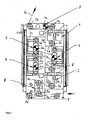
- Fig. 1 is assumed by a leveler, which consists of individual modules, which are arranged within a stable frame.
- a first module is formed by an infeed delay scan 1, which is arranged in the area of the goods inlet of the straightening machine.
- the infeed delay scan I consists of a scanning head bridge which comprises a plurality of photoelectric and / or optoelectronic measuring heads spaced over the width of the web. To adapt to the width of the web, the measuring heads on the Abtastkopfmaschine are also automatically, longitudinally displaceable.
- Another module consists of a runout delay scan 2.
- the infeed delay scan 1 registers the existing actual distortion of the supplied textile material web (see Fig. 3 , G). From the determined delay data, a control signal for the straightening modules 3 and / or 4 is provided.
- the straightening result is increased overall, ie, the amount of a non-distortion-corrected web is reduced , From the default signal obtained by the in-run delay scan 1, also in connection with the type of materials supplied, For example, woven or knitted fabric, an adjustment parameter for the downstream leveling module 3 and / or 4 determined.
- the first straightening module 3 includes at least one roller 3a in connection with a roller suspension 3b and a frame assembly 3c.
- the frame assembly 3c is together with the roller in the plane of Fig. 1 pivotable.
- the roller 3a can also be laterally raised or lowered.
- the respective straightening module 3, 4 may be enclosed by a housing 3d or 4d.
- the second straightening module 4 is constructed analogously to the straightening module 3 and in turn has a straightening roller 4a, a roller suspension 4b and adjusting devices or means for supporting the straightening module 4c.
- the control of the third straightening module 5 is effected by an output signal of the run-out delay scan 2, which has measuring heads 2a in combination with an opposite light source.
- the structure of the run-out delay scan 2 is substantially analogous to that according to run-in delay scan 1, which also comprises the measuring heads 1a with transmitted-light illumination units.
- the active part of the respective measuring head can scan the front or the back of the web. Measurements are possible both in transmitted and reflected light.
- a control loop is formed, that is, a still existing residual distortion is determined, and on the provision of a controlled variable to the straightening module 5, this delay is compensated, and Although until reaching a predetermined setpoint, ie it is continuously performed a target-IstVerrupt within the controlled system.
- the first straightening module 3 eliminates nearly 50% of the existing strains. Another delay is then eliminated by the second straightening module 4 and the residual distortion then from the third straightening module 5. Overall, less material leaves the machine without direction.
- the straightening modules 3, 4 and 5 with their mechanical elements, such as frames and / or adjusting devices, are subjected to a special color coding or have a correspondingly different color coating, for example in the order first straightening module 3 black, second straightening module 4 red, third straightening module 5 yellow.
- the web G according to Fig. 1 arrives at the figuratively illustrated embodiment of the straightening machine via a spreader roller 7a and the guide rollers 7b and 7c in the scanning of the intake delay scan 1, comprising the measuring heads 1a, and the deflection roller 1b in the first straightening module 3.
- a mechanical support 6 is provided which receives deflection rollers 2b.
- a dancer roller assembly 8 comprising two dancer rollers 8a may optionally connect.
- the dancer roller assembly 8 succeeds in setting a constant tension in the web, which is then led out via a guide module 9, comprising the rollers 9a and 8b, from the straightening machine and then, for example, reaches a clamping frame for fixing the weft position.
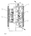
- a first directional module 3 and / or 4 there is a first scanhead bridge for forming an infeed scan 1 and a second scanhead bridge for forming a runout delay scan 2.
- the number of guide rollers 22 has been reduced to a minimum.
- Fig. 3 shows a block diagram representation of the control of the directional modules 3, 4 and 5.
- the infeed warp 1 detects the draft of the incoming web G and provides a control value which is also dependent on the type of material, e.g. Woven or knitted fabric, can be specified as a presettable meter.
- This default value passes in the sense of a feedforward control on electronic control blocks 10 and 13, which cause a symbolically shown adjustment of the roller 11 via drive means 12.
- the symbolically indicated roller 15 of the second straightening module 4 is also supplied, optionally with a modified signal, to an electronic control block 17 and activates the mechanical adjusting means 16.
- the adjustment can be made electromechanically, but also hydraulically.
- the third straightening module 5 with the straightening roller 19 shown symbolically also has adjusting means 20 which can be activated via the assemblies 21.
- adjusting means 20 which can be activated via the assemblies 21.
- a control loop is present.
- the discontinuity-delay scanning 2 determined by means of measuring heads located on a Abtastkopfmaschine (not shown), the remaining residual distortion of the web G. Then the straightening roller 19 is driven and there is a Determine how far this control step has been successful in judging. If there is still a (lesser) delay, the regulation becomes active again.
- the control circuit based on the straightening module 5 is symbolized by the dashed arrow.
Landscapes
- Engineering & Computer Science (AREA)
- Chemical & Material Sciences (AREA)
- Materials Engineering (AREA)
- Textile Engineering (AREA)
- Treatment Of Fiber Materials (AREA)
Claims (8)
- Dispositif de correction de distorsion d'une bande de tissu textile (G) transportée, dans lequel il est prévu au moins un premier module redresseur (3) côté entrée et un second module redresseur (5) côté sortie, qui présentent respectivement au moins un cylindre redresseur (3a, 5a) raccordé à une suspension de cylindre (3b, 5b) et un agencement de cadre (3c, 5c) pour corriger une trame oblique et une trame courbe, dans lequel l' agencement de cadre (3c, 5c) est conformé de manière à pouvoir pivoter avec le cylindre redresseur (3a, 5a),
dans lequel il est prévu des moyens pour émettre un signal pour faire fonctionner des unités d'entraînement et de réglage (12, 20) du cylindre redresseur respectif (11, 19), dans lequel il est prévu un organe de balayage de distorsion d'entrée (1) qui détermine une valeur de distorsion de la bande de tissu entrante (G),
dans lequel il est prévu un organe de balayage de distorsion de sortie (2) qui détermine la distorsion résiduelle de la bande de tissu (G) lorsqu'elle quitte le module redresseur (3) côté sortie ou après qu'elle l'a quitté, dans lequel les organes de balayages de distorsion d'entrée et de sortie (1, 2) sont constitués respectivement par un pont de balayage comprenant plusieurs têtes de balayage (1a, 2a), et
dans lequel une unité de commande est en communication avec l'organe de balayage de distorsion d'entrée (1) et le premier module redresseur (3) côté entrée et un circuit régulateur est formé en outre entre le module redresseur (5) côté sortie et l'organe de balayage de distorsion de sortie (2). - Dispositif selon la revendication 1, caractérisé en ce que chacun des cylindres redresseurs employés (11, 19) peut être commandé individuellement et dispose d'éléments de réglage correspondants (12, 20).
- Dispositif selon la revendication 1 ou 2, caractérisé en ce qu'il est prévu au moins un autre module redresseur (4) qui se trouve entre le module redresseur côté entrée (3) et le module redresseur côté sortie (5).
- Dispositif selon la revendication 3, caractérisé en ce que l'autre module redresseur (4) est en communication avec l'unité de commande.
- Dispositif selon l'une quelconque des revendications précédentes, caractérisé en ce que les têtes de balayage (1a, 2a) de l'organe de balayage de distorsion présentent une unité de balayage photoélectrique avec une lentille cylindrique oscillante ou rotative et une unité de balayage d'appareil photo optoélectronique.
- Dispositif selon l'une quelconque des revendications précédentes, caractérisé par une structure modulaire pour augmenter le nombre de cylindres redresseurs (11, 19) et donc de modules redresseurs (3, 4, 5).
- Dispositif selon l'une quelconque des revendications précédentes, caractérisé en ce que des cylindres de renvoi pour accroître le chemin de redressement pour des bandes de tissu plus rigides sont agencés entre les modules redresseurs (3, 4, 5).
- Procédé permettant la correction de distorsion avec un dispositif selon au moins l'une quelconque des revendications précédentes, caractérisé en ce que, par le biais d'un organe de balayage côté entrée de la bande de tissu (G), on détermine une distorsion d'entrée, d'où l'on tire un paramètre de réglage pour commander le premier module redresseur (1) côté entrée, dans lequel la distorsion résiduelle côté sortie est en outre établie pour faire fonctionner le second module redresseur (2) côté sortie en formant un circuit régulateur.
Applications Claiming Priority (1)
| Application Number | Priority Date | Filing Date | Title |
|---|---|---|---|
| DE200710035285 DE102007035285B4 (de) | 2007-07-27 | 2007-07-27 | Vorrichtung zur Verzugskorrektur einer geförderten, insbesondere textilen Warenbahn |
Publications (3)
| Publication Number | Publication Date |
|---|---|
| EP2019165A2 EP2019165A2 (fr) | 2009-01-28 |
| EP2019165A3 EP2019165A3 (fr) | 2009-03-18 |
| EP2019165B1 true EP2019165B1 (fr) | 2011-08-10 |
Family
ID=39855206
Family Applications (1)
| Application Number | Title | Priority Date | Filing Date |
|---|---|---|---|
| EP20080010852 Ceased EP2019165B1 (fr) | 2007-07-27 | 2008-06-14 | Dispositif destiné à corriger la déformation oblique et la déformation en arc d'une bande de marchandise transportée, en textile |
Country Status (2)
| Country | Link |
|---|---|
| EP (1) | EP2019165B1 (fr) |
| DE (1) | DE102007035285B4 (fr) |
Families Citing this family (6)
| Publication number | Priority date | Publication date | Assignee | Title |
|---|---|---|---|---|
| CN101818449B (zh) * | 2010-03-26 | 2011-10-19 | 顾金华 | 基于机器视觉的织物自动整花方法及其装置 |
| DE102011113665B4 (de) * | 2011-09-20 | 2016-01-07 | Mahlo Gmbh & Co. Kg | Nadelrichtanordnung zur Verzugskorrektur einer geförderten Warenbahn sowie ein zugehöriges Verfahren |
| CN103572481B (zh) * | 2013-11-25 | 2015-08-12 | 南通泰慕士服装有限公司 | 改善针织单面纬斜的方法 |
| CN105332255B (zh) * | 2015-11-30 | 2017-10-20 | 蚌埠市禹会区贵宾装饰材料商行 | 一种自动整纬装置 |
| CN108103756A (zh) * | 2018-01-26 | 2018-06-01 | 海宁鼎达纺织有限公司 | 一种原布质量检验装置 |
| CN111826925A (zh) * | 2020-08-24 | 2020-10-27 | 常州宏大智能装备产业发展研究院有限公司 | 一种织物整纬或整纬整花机构及方法 |
Family Cites Families (14)
| Publication number | Priority date | Publication date | Assignee | Title |
|---|---|---|---|---|
| DE1118140B (de) * | 1958-04-26 | 1961-11-30 | Mahlo Heinz Dr Ing | Vorrichtung zur Feststellung der Schussfadenlage in laufenden Gewebebahnen und zur Steuerung der Schussfaden-Richtapparaturen |
| CH473934A (de) | 1967-06-12 | 1969-06-15 | Eicken Henri | Vorrichtung zum Richten von Schussverziehungen oder Schussverschiebungen in Geweben |
| DE1906801A1 (de) * | 1969-02-11 | 1970-09-10 | Mahlo Gmbh | Vorrichtung zum Ausrichten laufender,verzogener Textilbahnen |
| JPS49133692A (fr) * | 1972-11-10 | 1974-12-23 | ||
| DE2850804C2 (de) * | 1978-11-23 | 1983-08-04 | Mahlo GmbH & Co KG, 8424 Saal | Verfahren und Vorrichtung zum Messen der Schußfadenlage einer laufenden textilen Warenbahn |
| JPH01192865A (ja) * | 1988-01-21 | 1989-08-02 | Santou Eng Kk | 布目矯正方法 |
| CS8905151A3 (en) * | 1989-09-07 | 1992-01-15 | Elitex Zavody Textilniho | Device for straightening weft threads in textile bands |
| DE19640023B4 (de) * | 1996-06-26 | 2006-06-29 | Mahlo Gmbh & Co Kg | Verfahren zur Verzugskorrektur |
| EP0816554B1 (fr) * | 1996-06-26 | 2003-04-02 | Mahlo GmbH & Co. KG | Procédé de correction d'étirage |
| JP3738375B2 (ja) * | 1997-02-24 | 2006-01-25 | セーレン電子株式会社 | 布目矯正装置 |
| DE10218334A1 (de) * | 2002-04-24 | 2003-11-06 | Mahlo Gmbh & Co Kg | Verfahren und Anordnung zum kontinuierlichen Faden- und/oder Maschenrichten bahnförmiger textiler Materialien |
| ITTO20030454A1 (it) * | 2003-06-17 | 2004-12-18 | Bianco Spa | Metodo e macchina per variare in un tessuto l'andamento |
| DE102004026978A1 (de) * | 2003-07-29 | 2005-05-19 | Mahlo Gmbh & Co. Kg | Verfahren zur Bewertung und nachfolgender Be- und/oder Verarbeitung textiler Warenbahnen |
| DE102006003384A1 (de) * | 2006-01-24 | 2007-07-26 | Brückner Trockentechnik GmbH & Co. KG | Vorrichtung zum Richten textiler Materialbahnen |
-
2007
- 2007-07-27 DE DE200710035285 patent/DE102007035285B4/de not_active Expired - Fee Related
-
2008
- 2008-06-14 EP EP20080010852 patent/EP2019165B1/fr not_active Ceased
Also Published As
| Publication number | Publication date |
|---|---|
| DE102007035285A1 (de) | 2009-01-29 |
| DE102007035285B4 (de) | 2014-11-20 |
| EP2019165A3 (fr) | 2009-03-18 |
| EP2019165A2 (fr) | 2009-01-28 |
Similar Documents
| Publication | Publication Date | Title |
|---|---|---|
| DE102007035285B4 (de) | Vorrichtung zur Verzugskorrektur einer geförderten, insbesondere textilen Warenbahn | |
| DE102007059185B4 (de) | Verfahren und Vorrichtung zur Messung der Geradheit von Langprodukten | |
| DE19936291B4 (de) | Bestimmung von Schnittlagen von Bahnsträngen in einer Rotationsdruckmaschine | |
| EP1573110B1 (fr) | Dispositif pour appreter des tissus denim | |
| EP0627508A1 (fr) | Appareil de diagnostic | |
| DE4128929C2 (de) | Vorrichtung zum Herstellen von Fasermaterial oder dergleichen mit vorgebbarem Vorlagegewicht | |
| DE69622032T2 (de) | Verbesserte Bandsägeblatt-Spannmaschine | |
| DE60108776T2 (de) | Vorrichtung zum kontinuierlichen Aufreihen rotationssymmetrischer Gegenstände - Verwendung zur visuellen Inspektion und Kontrolle | |
| DE4216686A1 (de) | Verfahren und Richtmaschine zum Richten von Blechen und Bändern | |
| DE4408099A1 (de) | Meß- und Steuereinrichtung | |
| AT524979B1 (de) | Drahtrichtmaschine und Verfahren zum Geraderichten von Draht oder Bandmaterial | |
| DE4118118C2 (de) | Nähmaschine mit einer Einrichtung zum Messen der Relativlage von Nähgutlagen-Endkanten | |
| EP1842666A2 (fr) | Procédé et dispositif destinés à l'impression d'objets en forme de plaques | |
| EP2112462A1 (fr) | Dispositif de mesure destiné à mesurer l'épaisseur de produits d'impression | |
| EP0816554A1 (fr) | Procédé et dispositif de correction d'étirage | |
| DE2356110C3 (de) | Vorrichtung zum Richten von Schräg- und Bogenverzügen bei Textilbahnen aller Art | |
| AT402746B (de) | Doppelsiebformer mit örtlich verstellbarer entwässerungsleiste | |
| DE19640023B4 (de) | Verfahren zur Verzugskorrektur | |
| DE102009012815A1 (de) | Messvorrichtung mit beweglicher Messeinrichtung in einer Druckmaschine | |
| DE102005022043B3 (de) | Verfahren und Vorrichtung zum Richten eines länglichen Werkstückes | |
| EP4334048B1 (fr) | Procédé et dispositif d'alignement d'au moins un guide latéral d'une cage de laminoir | |
| DE4104667A1 (de) | Verfahren zum anordnen von zuschnitteilen und einrichtung zum legen von stoffbahnen | |
| DE102012007079A1 (de) | Verfahren und Vorrichtung zum Zuführen von Wäschestücken zu einer Mangel oder dergleichen | |
| EP0747309A2 (fr) | Procédé et machine à tendre pour le traitement par chaleur d'une bande de matière textile | |
| DE2802466B2 (de) | Verfahren zum Messen der Abstände von Markierungen an einer Materialbahn, insbesondere zum Messen der Abstände der Transport-Randlochung an einer Endlospapierbahn, sowie Vorrichtung zur Ausführung dieses Verfahrens |
Legal Events
| Date | Code | Title | Description |
|---|---|---|---|
| PUAI | Public reference made under article 153(3) epc to a published international application that has entered the european phase |
Free format text: ORIGINAL CODE: 0009012 |
|
| AK | Designated contracting states |
Kind code of ref document: A2 Designated state(s): AT BE BG CH CY CZ DE DK EE ES FI FR GB GR HR HU IE IS IT LI LT LU LV MC MT NL NO PL PT RO SE SI SK TR |
|
| AX | Request for extension of the european patent |
Extension state: AL BA MK RS |
|
| PUAL | Search report despatched |
Free format text: ORIGINAL CODE: 0009013 |
|
| AK | Designated contracting states |
Kind code of ref document: A3 Designated state(s): AT BE BG CH CY CZ DE DK EE ES FI FR GB GR HR HU IE IS IT LI LT LU LV MC MT NL NO PL PT RO SE SI SK TR |
|
| AX | Request for extension of the european patent |
Extension state: AL BA MK RS |
|
| 17P | Request for examination filed |
Effective date: 20090529 |
|
| 17Q | First examination report despatched |
Effective date: 20090618 |
|
| AKX | Designation fees paid |
Designated state(s): DE IT |
|
| GRAP | Despatch of communication of intention to grant a patent |
Free format text: ORIGINAL CODE: EPIDOSNIGR1 |
|
| GRAS | Grant fee paid |
Free format text: ORIGINAL CODE: EPIDOSNIGR3 |
|
| GRAA | (expected) grant |
Free format text: ORIGINAL CODE: 0009210 |
|
| AK | Designated contracting states |
Kind code of ref document: B1 Designated state(s): DE IT |
|
| REG | Reference to a national code |
Ref country code: DE Ref legal event code: R096 Ref document number: 502008004453 Country of ref document: DE Effective date: 20111006 |
|
| PLBE | No opposition filed within time limit |
Free format text: ORIGINAL CODE: 0009261 |
|
| STAA | Information on the status of an ep patent application or granted ep patent |
Free format text: STATUS: NO OPPOSITION FILED WITHIN TIME LIMIT |
|
| 26N | No opposition filed |
Effective date: 20120511 |
|
| REG | Reference to a national code |
Ref country code: DE Ref legal event code: R097 Ref document number: 502008004453 Country of ref document: DE Effective date: 20120511 |
|
| PGFP | Annual fee paid to national office [announced via postgrant information from national office to epo] |
Ref country code: IT Payment date: 20190624 Year of fee payment: 12 |
|
| PGFP | Annual fee paid to national office [announced via postgrant information from national office to epo] |
Ref country code: DE Payment date: 20190626 Year of fee payment: 12 |
|
| REG | Reference to a national code |
Ref country code: DE Ref legal event code: R119 Ref document number: 502008004453 Country of ref document: DE |
|
| PG25 | Lapsed in a contracting state [announced via postgrant information from national office to epo] |
Ref country code: DE Free format text: LAPSE BECAUSE OF NON-PAYMENT OF DUE FEES Effective date: 20210101 |
|
| PG25 | Lapsed in a contracting state [announced via postgrant information from national office to epo] |
Ref country code: IT Free format text: LAPSE BECAUSE OF NON-PAYMENT OF DUE FEES Effective date: 20200614 |