EP2019189B1 - Dispositif de distribution variable - Google Patents
Dispositif de distribution variable Download PDFInfo
- Publication number
- EP2019189B1 EP2019189B1 EP07742478A EP07742478A EP2019189B1 EP 2019189 B1 EP2019189 B1 EP 2019189B1 EP 07742478 A EP07742478 A EP 07742478A EP 07742478 A EP07742478 A EP 07742478A EP 2019189 B1 EP2019189 B1 EP 2019189B1
- Authority
- EP
- European Patent Office
- Prior art keywords
- valves
- control chamber
- valve
- driving device
- cam
- Prior art date
- Legal status (The legal status is an assumption and is not a legal conclusion. Google has not performed a legal analysis and makes no representation as to the accuracy of the status listed.)
- Not-in-force
Links
- 239000012530 fluid Substances 0.000 claims abstract description 24
- 238000003780 insertion Methods 0.000 claims abstract description 7
- 230000037431 insertion Effects 0.000 claims abstract description 7
- 238000003825 pressing Methods 0.000 claims abstract description 6
- 238000007599 discharging Methods 0.000 claims description 2
- 238000010586 diagram Methods 0.000 description 7
- 238000002485 combustion reaction Methods 0.000 description 2
- 230000003111 delayed effect Effects 0.000 description 2
- 230000000694 effects Effects 0.000 description 2
- 230000006835 compression Effects 0.000 description 1
- 238000007906 compression Methods 0.000 description 1
- 239000000446 fuel Substances 0.000 description 1
- 238000004519 manufacturing process Methods 0.000 description 1
- KJFBVJALEQWJBS-XUXIUFHCSA-N maribavir Chemical compound CC(C)NC1=NC2=CC(Cl)=C(Cl)C=C2N1[C@H]1O[C@@H](CO)[C@H](O)[C@@H]1O KJFBVJALEQWJBS-XUXIUFHCSA-N 0.000 description 1
- 238000000034 method Methods 0.000 description 1
- 230000004048 modification Effects 0.000 description 1
- 238000012986 modification Methods 0.000 description 1
Images


Classifications
-
- F—MECHANICAL ENGINEERING; LIGHTING; HEATING; WEAPONS; BLASTING
- F01—MACHINES OR ENGINES IN GENERAL; ENGINE PLANTS IN GENERAL; STEAM ENGINES
- F01L—CYCLICALLY OPERATING VALVES FOR MACHINES OR ENGINES
- F01L1/00—Valve-gear or valve arrangements, e.g. lift-valve gear
- F01L1/26—Valve-gear or valve arrangements, e.g. lift-valve gear characterised by the provision of two or more valves operated simultaneously by same transmitting-gear; peculiar to machines or engines with more than two lift-valves per cylinder
- F01L1/267—Valve-gear or valve arrangements, e.g. lift-valve gear characterised by the provision of two or more valves operated simultaneously by same transmitting-gear; peculiar to machines or engines with more than two lift-valves per cylinder with means for varying the timing or the lift of the valves
-
- F—MECHANICAL ENGINEERING; LIGHTING; HEATING; WEAPONS; BLASTING
- F01—MACHINES OR ENGINES IN GENERAL; ENGINE PLANTS IN GENERAL; STEAM ENGINES
- F01L—CYCLICALLY OPERATING VALVES FOR MACHINES OR ENGINES
- F01L1/00—Valve-gear or valve arrangements, e.g. lift-valve gear
- F01L1/12—Transmitting gear between valve drive and valve
- F01L1/18—Rocking arms or levers
- F01L1/181—Centre pivot rocking arms
-
- F—MECHANICAL ENGINEERING; LIGHTING; HEATING; WEAPONS; BLASTING
- F01—MACHINES OR ENGINES IN GENERAL; ENGINE PLANTS IN GENERAL; STEAM ENGINES
- F01L—CYCLICALLY OPERATING VALVES FOR MACHINES OR ENGINES
- F01L1/00—Valve-gear or valve arrangements, e.g. lift-valve gear
- F01L1/20—Adjusting or compensating clearance
- F01L1/22—Adjusting or compensating clearance automatically, e.g. mechanically
- F01L1/24—Adjusting or compensating clearance automatically, e.g. mechanically by fluid means, e.g. hydraulically
-
- F—MECHANICAL ENGINEERING; LIGHTING; HEATING; WEAPONS; BLASTING
- F01—MACHINES OR ENGINES IN GENERAL; ENGINE PLANTS IN GENERAL; STEAM ENGINES
- F01L—CYCLICALLY OPERATING VALVES FOR MACHINES OR ENGINES
- F01L1/00—Valve-gear or valve arrangements, e.g. lift-valve gear
- F01L1/26—Valve-gear or valve arrangements, e.g. lift-valve gear characterised by the provision of two or more valves operated simultaneously by same transmitting-gear; peculiar to machines or engines with more than two lift-valves per cylinder
-
- F—MECHANICAL ENGINEERING; LIGHTING; HEATING; WEAPONS; BLASTING
- F01—MACHINES OR ENGINES IN GENERAL; ENGINE PLANTS IN GENERAL; STEAM ENGINES
- F01L—CYCLICALLY OPERATING VALVES FOR MACHINES OR ENGINES
- F01L13/00—Modifications of valve-gear to facilitate reversing, braking, starting, changing compression ratio, or other specific operations
- F01L13/06—Modifications of valve-gear to facilitate reversing, braking, starting, changing compression ratio, or other specific operations for braking
- F01L13/065—Compression release engine retarders of the "Jacobs Manufacturing" type
-
- F—MECHANICAL ENGINEERING; LIGHTING; HEATING; WEAPONS; BLASTING
- F01—MACHINES OR ENGINES IN GENERAL; ENGINE PLANTS IN GENERAL; STEAM ENGINES
- F01L—CYCLICALLY OPERATING VALVES FOR MACHINES OR ENGINES
- F01L13/00—Modifications of valve-gear to facilitate reversing, braking, starting, changing compression ratio, or other specific operations
- F01L13/0015—Modifications of valve-gear to facilitate reversing, braking, starting, changing compression ratio, or other specific operations for optimising engine performances by modifying valve lift according to various working parameters, e.g. rotational speed, load, torque
- F01L2013/0089—Modifications of valve-gear to facilitate reversing, braking, starting, changing compression ratio, or other specific operations for optimising engine performances by modifying valve lift according to various working parameters, e.g. rotational speed, load, torque with means for delaying valve closing
Definitions
- the present invention relates to a valve driving device of an engine, and more particularly to a valve driving device which can change the closing timing of valves.
- variable valve driving device disclosed in Patent Document 1 has been suggested as a device capable of changing the closing timing of intake valves.
- Patent Document 1 discloses a variable valve driving device including a plunger that is driven by a cam in a cylinder head of an engine, an actuator for pressing an intake valve communicating with a plunger chamber pressurized by the plunger yin the valve opening direction, a hydraulic pump for supplying hydraulic pressure into the plunger chamber, a hydraulic chamber provided between a retainer of the intake valve and the cylinder head and pressing the intake valve in the valve closing direction, switching means inserted into a channel which links the plunger chamber to the hydraulic chamber, and an accumulator connected between the hydraulic chamber of the channel and the switching means.
- variable valve driving device when the intake valve is lifted, the plunger chamber and hydraulic chamber are disconnected by the switching means, the actuator is driven by a hydraulic pressure of the plunger chamber which is pressurized by the plunger driven by the cam, and the intake valve is opened.
- the hydraulic pressure of the hydraulic chamber pressurized as the intake valve is opened is accumulated in the accumulator.
- variable valve driving device because the lift amount of the intake valve changes depending on the compressibility of the working oil in the plunger chamber and the like, the lift amount of the intake valve is difficult to control with good accuracy.
- variable valve driving device because the scope of changes introduced in the conventional valve driving device of a cam system is significant and the structure is complex, the production cost rises.
- variable valve driving device which can accurately control the lift amount of the valves and can be manufactured at a low cost.
- the invention set forth in claim 1 provides a variable valve driving device, comprising valves serving as intake valves or exhaust valves of an engine, springs for biasing the valves in the valve closing direction, a cam for pressing the valves in the valve opening direction against a biasing force of the springs, a piston joined to the valves, a control chamber configured by a piston insertion hole into which the piston is inserted, and a control mechanism for changing a valve closing timing of the valves by controlling the introduction and discharge of a working fluid into and from the control chamber.
- the invention set forth in claim 2 provides the variable valve driving device according to claim 1, wherein when the valves are closed with a delay with respect to the valve closing timing corresponding to a cam profile of the cam, the control mechanism regulates the discharge of the working fluid introduced into the control chamber, whereby the working fluid is held in the control chamber.
- the invention set forth in claim 3 provides the variable valve driving device according to claim 1 or 2, wherein the control mechanism has a working fluid tank connected to the control chamber, a first actuation valve for introducing the working fluid of the working fluid tank into the control chamber, and a second actuation valve for discharging the working fluid of the control chamber into the working fluid tank.
- the invention set forth in claim 4 provides the variable valve driving device according to any of claims 1 to 3, wherein the valves are pressed by the cam directly or pressed by the cam via a rocker arm.
- the invention set forth in claim 5 provides the variable valve driving device according to any of claims 1 to 4, wherein the control chamber is disposed on the side opposite the valves with respect to a pressure application point in which the cam or the rocker arm presses the valves.
- variable valve driving device according to any of claims 1 to 5, wherein the control chamber is disposed on an extension of an axial line of the valves.
- the present invention demonstrates an excellent effect of being capable of providing a variable valve driving device which can accurately control the lift amount of the valve and can be manufactured at a low cost.
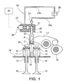
- FIG. 1 is a schematic diagram of a variable valve driving device of one embodiment of the present invention.
- variable valve driving device of the present embodiment is applied to a four-valve engine.
- variable valve driving device of the present embodiment includes valves (engine valves) 10 serving as intake valves or exhaust valves of an engine, springs (valve springs) 11 for biasing the valves 10 in the valve closing direction (upward direction in FIG. 1 ), and a cam 12 for pressing the valves 10 in the valve opening direction (downward direction in FIG. 1 ) against a biasing force of the springs 11.
- the valve 10 is supported by a cylinder head 14 at a valve stem 13 thereof so that the valve 10 can move up and down in the cylinder head 14.
- a retainer (valve retainer) 15 is attached to the valve 10, and the spring 11 is installed in a compressed state between the retainer 15 and the cylinder head 14.
- a bridge (valve bridge) 16 of an approximately T-like shape is attached to the valves 10, and a rocker arm 17 is engaged with the upper portion of the bridge 16.
- the bridge 16 is supported on a guide pin 18 which is fixedly attached to the cylinder head 14, so that the bridge 16 can move up and down.
- the cam 12 is designed to press the valves 10 via the rocker arm 17. In other words, the valves 10 are pressed by the cam 12 via the rocker arm 17.
- variable valve driving device of the present embodiment includes a piston (plunger) 19 joined to the valves 10 and installed in a position in which it is not directly pressed by the cam 12, and a control chamber 21 configured by a piston insertion hole 20 into which the piston 19 can be inserted.
- a bridge-like auxiliary member 22 having formed therein an opening for passing the rocker arm 17 therethrough is attached to the upper portion of the bridge 16, and the piston 19 is attached to the upper portion of the auxiliary member 22.
- the control chamber 21 is bounded and formed by the piston insertion hole 20 formed in a housing 23 and the upper surface of the piston 19 inserted into the piston insertion hole 20.
- the housing 23 is fixedly attached to the cylinder head 14 (this is not shown in the figure).
- the control chamber 21 is installed on the side opposite the valves 10 (upper side in FIG. 1 ) with respect to a pressure application point P in which the rocker arm 17 presses the valves 10 (bridge 16). Further, the control chamber 21 is disposed on an extension of an axial line C of the valves 10 (bridge 16).
- the variable valve driving device of the present embodiment includes a control mechanism 24 for changing the valve closing timing of the valves 10 by controlling the introduction and discharge of a working fluid (working oil) into and from the control chamber 21.
- the control mechanism 24 has a working fluid tank (working oil tank) 26 connected to the control chamber 21 via an introduction line 25a and a discharge line 25b, a first actuation valve 27 provided in the intermediate section of the introduction line 25a and serving to introduce the working oil of the working oil tank 26 into the control chamber 21, and a second actuation valve 28 provided in the intermediate section of the discharge line 25b and serving to discharge the working fluid of the control chamber 21 into the working oil tank 26.
- working fluid tank working oil tank
- the first actuation valve 27 is composed of a check valve (backflow preventing valve).
- the side of the working fluid tank 26 is an inlet side
- the side of the control chamber 21 is an outlet side. Once the pressure inside the control chamber 21 becomes negative, the check valve 27 is immediately opened, and when the check valve 27 is open, the working oil of the working oil tank 26 can be introduced into the control chamber 21.
- the second actuation valve 28 is composed of a control valve (electromagnetic valve). The opening and closing of the control valve 28 is controlled by a controller 29, and when the control valve 28 is open, the working fluid of the control chamber 21 can be discharged into the working oil tank 26.
- the control valve 28 may be of an NO (normally open) type or an NC (normally closed) type.
- control valve 28 is of an NC type.
- valves 10 are pressed by the cam 12 in the valve opening direction against the biasing force of the springs 11, and the valves 10 are opened following the cam profile (shape of cam peak) of the cam 12 (see FIG. 3(c) ).
- the piston 19 joined to the valves 10 (bridge 16) is also moved in the valve opening direction of the valves 10.
- valves 10 When the valves 10 are closed with a delay with respect to the valve closing timing corresponding to the cam profile of the cam 12 (when a delayed closing operation is performed), the control valve 28 remains closed when the cam 12 moves to the valve closing side over the peak position.
- valves 10 are moved in the valve closing direction by the biasing force of the springs 11.
- the piston 19 is also moved in the valve closing direction of the valves 10.
- valves 10 can be held in an open state.
- valve 16 and piston 19 are moved in the valve closing direction by the biasing force of the springs 11. Therefore, the working oil of the control chamber 21 is discharged by the piston 19 into the working oil tank 26 via the discharge line 25b.
- the valves 10 can thus be closed with a delay with respect to the valve closing timing corresponding to the cam profile of the cam 12.
- valves 10 are closed at a valve closing timing corresponding to the cam profile of the cam 12 (the case in which normal operation is performed)
- the control valve 28 is opened at a timing close to the peak position of the cam 12 (see a broken line in FIG. 3(a) ).
- control chamber 21 is not tightly closed when the valves 10 are closed, the valves 10 and piston 19 are moved by the biasing force of the springs 11 in the valve closing direction (see broken line in FIG. 3(c) ) and the working oil of the control chamber 21 is discharged by the piston 19 into the working oil tank 26 via the discharge line 25b. Therefore, the pressure in the control chamber 21 does not rise and the valve closing operation of the valves 10 is practically identical to that of the conventional cam drive system.
- the valves 10 operate following the cam profile of the cam 12 in a larger part of the range, except the case when the delayed closing operation of the valves 10 is performed. Therefore, the lift amount of the valves 10 can be controlled more accurately than in a variable valve driving device which opens and closes the valves hydraulically.
- the scope of changes introduced in the conventional valve driving device of a cam system is small and the structure is not more complex than that of the variable valve driving device which opens and closes the valves hydraulically. Therefore, the device can be manufactured at a low cost.
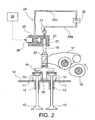
- valves 10 may be directly pressed by the cam 12, as shown in FIG. 4 .
- a tappet (valve lifter) 30 is attached to the valve 10, and the spring 11 is disposed in a compressed state between the tappet 30 and the cylinder head 14.
- a bridge-like auxiliary member 31 having formed therein an opening for passing a camshaft therethrough is attached to the upper portion of the tappet 30, and the piston 19 is attached to the upper portion of the auxiliary member 31.
- control chamber 21 may not be installed on the extension of the axial line C of the valves 10 (bridge 16).
- piston 19 may be attached to the retainer 15, valve stem 13, or rocker arm 17.
Landscapes
- Engineering & Computer Science (AREA)
- Mechanical Engineering (AREA)
- General Engineering & Computer Science (AREA)
- Valve Device For Special Equipments (AREA)
- Valve-Gear Or Valve Arrangements (AREA)
Abstract
Claims (6)
- Dispositif de commande de soupape variable comprenant des soupapes (10) qui servent de soupapes d'admission ou de soupapes d'échappement d'un moteur, des ressorts (11) permettant d'incliner les soupapes (10) dans le sens de fermeture des soupapes, une came (12) permettant d'appuyer sur les soupapes (10) dans le sens de l'ouverture des soupapes en s'opposant à une force d'inclinaison des ressorts (11), un piston (19), une chambre de contrôle (21) configurée par un trou d'insertion du piston (20) dans lequel le piston (19) est inséré, et un mécanisme de commande (24) permettant de modifier une temporisation de fermeture de soupape des soupapes (10) en commandant l'introduction dans, et le refoulement d'un fluide actif de la chambre de contrôle (21), caractérisé en ce que
le piston (19) est réuni aux soupapes (10) de telle sorte que le piston (19) se déplace également dans le sens de l'ouverture des soupapes (10) lorsque les soupapes (10) sont ouvertes, de telle sorte que la pression dans la chambre de contrôle (21) devient une pression négative, grâce à quoi le fluide actif est introduit dans la chambre de contrôle (21). - Dispositif de commande de soupape variable selon la revendication 1, dans lequel, lorsque les soupapes (10) sont fermées avec un retard par rapport à la temporisation de fermeture des soupapes correspondant à un profil de came de la came (12), le mécanisme de commande (24) régule le refoulement du fluide actif introduit dans la chambre de contrôle (21), grâce à quoi le fluide actif est retenu dans la chambre de contrôle (21).
- Dispositif de commande de soupape variable selon la revendication 1 ou 2, dans lequel le mécanisme de commande (24) possède un réservoir de fluide actif (26) raccordé à la chambre de contrôle (21), une première soupape d'actionnement (27) permettant d'introduire le fluide actif du réservoir de fluide actif (26) dans la chambre de contrôle (21), et une seconde soupape d'actionnement (28) permettant de refouler le fluide actif de la chambre de contrôle (21) vers le réservoir de fluide actif (26).
- Dispositif de commande de soupape variable selon l'une quelconque des revendications 1 à 3, dans lequel la came (12) appuie directement ou bien la came (12) appuie via un culbuteur (17) sur les soupapes (10).
- Dispositif de commande de soupape variable selon l'une quelconque des revendications 1 à 4, dans lequel la chambre de contrôle (21) est disposée du côté opposé aux soupapes (10) par rapport à un point d'application de la pression (P), dans lequel la came (12) ou le culbuteur (17) appuie sur les soupapes (10).
- Dispositif de commande de soupape variable selon l'une quelconque des revendications 1 à 5, dans lequel la chambre de contrôle (21) est disposée sur un prolongement d'une ligne axiale (C) des soupapes (10).
Applications Claiming Priority (2)
| Application Number | Priority Date | Filing Date | Title |
|---|---|---|---|
| JP2006135002A JP5011816B2 (ja) | 2006-05-15 | 2006-05-15 | 可変動弁駆動装置 |
| PCT/JP2007/059043 WO2007132662A1 (fr) | 2006-05-15 | 2007-04-26 | Dispositif de distribution variable |
Publications (3)
| Publication Number | Publication Date |
|---|---|
| EP2019189A1 EP2019189A1 (fr) | 2009-01-28 |
| EP2019189A4 EP2019189A4 (fr) | 2011-01-26 |
| EP2019189B1 true EP2019189B1 (fr) | 2012-04-18 |
Family
ID=38693761
Family Applications (1)
| Application Number | Title | Priority Date | Filing Date |
|---|---|---|---|
| EP07742478A Not-in-force EP2019189B1 (fr) | 2006-05-15 | 2007-04-26 | Dispositif de distribution variable |
Country Status (5)
| Country | Link |
|---|---|
| US (1) | US8091522B2 (fr) |
| EP (1) | EP2019189B1 (fr) |
| JP (1) | JP5011816B2 (fr) |
| CN (1) | CN101443532B (fr) |
| WO (1) | WO2007132662A1 (fr) |
Families Citing this family (20)
| Publication number | Priority date | Publication date | Assignee | Title |
|---|---|---|---|---|
| EP2044305A4 (fr) * | 2006-07-26 | 2010-11-17 | J Michael Langham | Moteur hydraulique |
| EP2055906A1 (fr) * | 2007-10-31 | 2009-05-06 | Caterpillar Motoren GmbH & Co. KG | Dispositif et procédé de contrôle de soupapes |
| JP5071234B2 (ja) * | 2008-05-13 | 2012-11-14 | いすゞ自動車株式会社 | 内燃機関の可変動弁装置 |
| DE102008049181A1 (de) * | 2008-09-26 | 2010-04-01 | Schaeffler Kg | Elektrohydraulische Ventilsteuerung |
| JP2010121570A (ja) * | 2008-11-20 | 2010-06-03 | Komatsu Ltd | 可変弁装置およびその制御方法 |
| JP5332896B2 (ja) * | 2009-05-19 | 2013-11-06 | いすゞ自動車株式会社 | 可変動弁機構 |
| JP5463837B2 (ja) * | 2009-10-06 | 2014-04-09 | いすゞ自動車株式会社 | 内燃機関 |
| JP5577733B2 (ja) * | 2010-02-17 | 2014-08-27 | いすゞ自動車株式会社 | 可変動弁機構の油圧ダンピング構造 |
| FI122253B (fi) * | 2010-04-30 | 2011-10-31 | Waertsilae Finland Oy | Parannettu ohjausjärjestely mäntämoottorin kaasunvaihtoventtiiliä varten |
| EP2597276B1 (fr) | 2011-11-24 | 2014-04-16 | C.R.F. Società Consortile per Azioni | Moteur avec un mécanisme de distribution variable avec une électrovanne a troi voies |
| KR101305200B1 (ko) | 2011-12-07 | 2013-09-12 | 현대자동차주식회사 | Ehv 시스템 |
| EP2693009B1 (fr) * | 2012-07-31 | 2014-12-10 | C.R.F. Società Consortile per Azioni | Moteur à combustion interne présentant un système pour l'actionnement variable des soupapes d'admission pourvues de soupapes à solénoïde à trois voies et procédé pour commander ce moteur |
| FI20135003L (fi) * | 2013-01-03 | 2014-07-04 | Waertsilae Finland Oy | Pakoventtiilijärjestely ja menetelmä pakoventtiilin sulkeutumisen kontrolloimiseksi |
| US9309788B2 (en) | 2013-07-19 | 2016-04-12 | Electro-Motive Diesel, Inc. | Valve bridge assembly having replaceable sleeve inserts |
| US9506382B2 (en) | 2015-03-30 | 2016-11-29 | Caterpillar Inc. | Variable valve actuator |
| MD4432C1 (ro) * | 2015-07-23 | 2017-03-31 | Олег ПЕТРОВ | Dispozitiv pentru dirijarea fazelor de distribuţie a gazelor şi a cursei supapei mecanismului de distribuţie a gazelor (variante) |
| MD4433C1 (ro) * | 2015-07-23 | 2017-03-31 | Олег ПЕТРОВ | Dispozitiv pentru dirijarea fazelor de distribuţie a gazelor şi a cursei supapei mecanismului de distribuţie a gazelor (variante) |
| CN107387189B (zh) * | 2017-08-31 | 2023-06-23 | 吉林大学 | 一种可变气门驱动机构 |
| WO2023037321A1 (fr) * | 2021-09-10 | 2023-03-16 | Jacobs Vehicle Systems, Inc. | Ensemble culbuteur de fermeture de soupape en deux étapes |
| WO2023174582A1 (fr) * | 2022-03-15 | 2023-09-21 | Eaton Intelligent Power Limited | Stabilisateur de pont de soupape pour freinage de moteur |
Family Cites Families (7)
| Publication number | Priority date | Publication date | Assignee | Title |
|---|---|---|---|---|
| JP2970388B2 (ja) | 1994-03-25 | 1999-11-02 | 三菱自動車工業株式会社 | 内燃エンジンの可変動弁装置 |
| US6701888B2 (en) * | 2000-12-01 | 2004-03-09 | Caterpillar Inc | Compression brake system for an internal combustion engine |
| US6732685B2 (en) | 2002-02-04 | 2004-05-11 | Caterpillar Inc | Engine valve actuator |
| US20040083994A1 (en) * | 2002-10-30 | 2004-05-06 | Homa Afjeh | System for actuating an engine valve |
| US7121523B2 (en) * | 2003-12-08 | 2006-10-17 | Caterpillar Inc | Fluid control valve |
| JP2006097534A (ja) * | 2004-09-29 | 2006-04-13 | Hino Motors Ltd | 可変バルブ機構 |
| US6997148B1 (en) * | 2004-10-15 | 2006-02-14 | Caterpillar Inc. | Engine valve actuator |
-
2006
- 2006-05-15 JP JP2006135002A patent/JP5011816B2/ja not_active Expired - Fee Related
-
2007
- 2007-04-26 EP EP07742478A patent/EP2019189B1/fr not_active Not-in-force
- 2007-04-26 WO PCT/JP2007/059043 patent/WO2007132662A1/fr not_active Ceased
- 2007-04-26 CN CN2007800176666A patent/CN101443532B/zh not_active Expired - Fee Related
- 2007-04-26 US US12/300,467 patent/US8091522B2/en not_active Expired - Fee Related
Also Published As
| Publication number | Publication date |
|---|---|
| US20090250023A1 (en) | 2009-10-08 |
| US8091522B2 (en) | 2012-01-10 |
| EP2019189A4 (fr) | 2011-01-26 |
| CN101443532A (zh) | 2009-05-27 |
| JP5011816B2 (ja) | 2012-08-29 |
| JP2007303438A (ja) | 2007-11-22 |
| CN101443532B (zh) | 2012-05-16 |
| EP2019189A1 (fr) | 2009-01-28 |
| WO2007132662A1 (fr) | 2007-11-22 |
Similar Documents
| Publication | Publication Date | Title |
|---|---|---|
| EP2019189B1 (fr) | Dispositif de distribution variable | |
| WO2012048300A4 (fr) | Systèmes de commande de soupape (desmodromique) pour moteurs à combustion interne | |
| KR100482901B1 (ko) | 내연기관에사용되는연료분사장치 | |
| US6935287B2 (en) | System and method for actuating an engine valve | |
| EP2315919B1 (fr) | Dispositif de commande dans un moteur a piston | |
| EP2872748B1 (fr) | Actionneur pour déplacement axial d'une soupape d'échange de gaz dans un moteur à combustion | |
| EP2722499B1 (fr) | Appareil de contrôle de la synchronisation d'une soupape variable | |
| JPH11509601A (ja) | エンジンシリンダのプッシュプルバルブ組立体 | |
| KR101244845B1 (ko) | 엔진의 가변밸브 리프트 장치 | |
| US7610881B2 (en) | Apparatus for an internal combustion engine | |
| CN108397252B (zh) | 液压间隙调节器 | |
| EP1845245A1 (fr) | Procede et dispositif de commande de soupape d'echappement pour moteur diesel | |
| US10823018B1 (en) | Valve train arrangement including engine brake system and lost-motion hydraulic lash adjuster | |
| CN105814290B (zh) | 排气阀驱动装置以及具有该排气阀驱动装置的内燃机 | |
| US6769385B1 (en) | System for controlling engine valve seating velocity | |
| EP3901426B1 (fr) | Dispositif de commande des soupapes et moteur | |
| JPH09112234A (ja) | エンジンのバルブメカニズム | |
| KR101558348B1 (ko) | 유압 전자 제어 밸브 기구 | |
| KR970004454Y1 (ko) | 엔진 흡배기 밸브의 유압식 개폐장치 | |
| JP4227965B2 (ja) | 電磁制御燃料噴射装置 | |
| KR101449070B1 (ko) | 유압타입 실린더 디엑티베이션장치 | |
| KR102185712B1 (ko) | 가변밸브 타이밍 장치 | |
| JPS62203911A (ja) | デイ−ゼル機関のバルブタイミング変更装置 | |
| KR100534929B1 (ko) | 내연기관의 흡/배기밸브용 전환가능한 태핏과 이의 구동장치 | |
| JP5332896B2 (ja) | 可変動弁機構 |
Legal Events
| Date | Code | Title | Description |
|---|---|---|---|
| PUAI | Public reference made under article 153(3) epc to a published international application that has entered the european phase |
Free format text: ORIGINAL CODE: 0009012 |
|
| 17P | Request for examination filed |
Effective date: 20081031 |
|
| AK | Designated contracting states |
Kind code of ref document: A1 Designated state(s): AT BE BG CH CY CZ DE DK EE ES FI FR GB GR HU IE IS IT LI LT LU LV MC MT NL PL PT RO SE SI SK TR |
|
| AX | Request for extension of the european patent |
Extension state: AL BA HR MK RS |
|
| RBV | Designated contracting states (corrected) |
Designated state(s): DE FR GB IT |
|
| A4 | Supplementary search report drawn up and despatched |
Effective date: 20101227 |
|
| GRAP | Despatch of communication of intention to grant a patent |
Free format text: ORIGINAL CODE: EPIDOSNIGR1 |
|
| DAX | Request for extension of the european patent (deleted) | ||
| GRAS | Grant fee paid |
Free format text: ORIGINAL CODE: EPIDOSNIGR3 |
|
| GRAA | (expected) grant |
Free format text: ORIGINAL CODE: 0009210 |
|
| RIN1 | Information on inventor provided before grant (corrected) |
Inventor name: TANAKA, TSUNEO Inventor name: TOKUMARU, TAKESHI Inventor name: NISHIMURA, TERUKAZU Inventor name: MINATO, AKIHIKO |
|
| AK | Designated contracting states |
Kind code of ref document: B1 Designated state(s): DE FR GB IT |
|
| REG | Reference to a national code |
Ref country code: GB Ref legal event code: FG4D |
|
| REG | Reference to a national code |
Ref country code: DE Ref legal event code: R096 Ref document number: 602007022105 Country of ref document: DE Effective date: 20120614 |
|
| PLBE | No opposition filed within time limit |
Free format text: ORIGINAL CODE: 0009261 |
|
| STAA | Information on the status of an ep patent application or granted ep patent |
Free format text: STATUS: NO OPPOSITION FILED WITHIN TIME LIMIT |
|
| PG25 | Lapsed in a contracting state [announced via postgrant information from national office to epo] |
Ref country code: IT Free format text: LAPSE BECAUSE OF FAILURE TO SUBMIT A TRANSLATION OF THE DESCRIPTION OR TO PAY THE FEE WITHIN THE PRESCRIBED TIME-LIMIT Effective date: 20120418 |
|
| 26N | No opposition filed |
Effective date: 20130121 |
|
| REG | Reference to a national code |
Ref country code: DE Ref legal event code: R097 Ref document number: 602007022105 Country of ref document: DE Effective date: 20130121 |
|
| PGFP | Annual fee paid to national office [announced via postgrant information from national office to epo] |
Ref country code: GB Payment date: 20130424 Year of fee payment: 7 Ref country code: DE Payment date: 20130508 Year of fee payment: 7 |
|
| PGFP | Annual fee paid to national office [announced via postgrant information from national office to epo] |
Ref country code: FR Payment date: 20130625 Year of fee payment: 7 |
|
| REG | Reference to a national code |
Ref country code: DE Ref legal event code: R119 Ref document number: 602007022105 Country of ref document: DE |
|
| GBPC | Gb: european patent ceased through non-payment of renewal fee |
Effective date: 20140426 |
|
| REG | Reference to a national code |
Ref country code: FR Ref legal event code: ST Effective date: 20141231 |
|
| PG25 | Lapsed in a contracting state [announced via postgrant information from national office to epo] |
Ref country code: DE Free format text: LAPSE BECAUSE OF NON-PAYMENT OF DUE FEES Effective date: 20141101 Ref country code: GB Free format text: LAPSE BECAUSE OF NON-PAYMENT OF DUE FEES Effective date: 20140426 |
|
| REG | Reference to a national code |
Ref country code: DE Ref legal event code: R119 Ref document number: 602007022105 Country of ref document: DE Effective date: 20141101 |
|
| PG25 | Lapsed in a contracting state [announced via postgrant information from national office to epo] |
Ref country code: FR Free format text: LAPSE BECAUSE OF NON-PAYMENT OF DUE FEES Effective date: 20140430 |