EP2019390A2 - Composite noise killer cell - Google Patents
Composite noise killer cell Download PDFInfo
- Publication number
- EP2019390A2 EP2019390A2 EP08019194A EP08019194A EP2019390A2 EP 2019390 A2 EP2019390 A2 EP 2019390A2 EP 08019194 A EP08019194 A EP 08019194A EP 08019194 A EP08019194 A EP 08019194A EP 2019390 A2 EP2019390 A2 EP 2019390A2
- Authority
- EP
- European Patent Office
- Prior art keywords
- sound
- noise
- active
- insulation wall
- noise insulation
- Prior art date
- Legal status (The legal status is an assumption and is not a legal conclusion. Google has not performed a legal analysis and makes no representation as to the accuracy of the status listed.)
- Withdrawn
Links
- 239000002131 composite material Substances 0.000 title claims abstract description 24
- 238000009413 insulation Methods 0.000 claims abstract description 204
- 230000003247 decreasing effect Effects 0.000 claims abstract description 57
- 238000001514 detection method Methods 0.000 claims abstract description 28
- 230000009467 reduction Effects 0.000 description 137
- 230000001603 reducing effect Effects 0.000 description 29
- 230000007423 decrease Effects 0.000 description 27
- 230000000694 effects Effects 0.000 description 15
- 239000000463 material Substances 0.000 description 13
- 238000009434 installation Methods 0.000 description 10
- 230000004048 modification Effects 0.000 description 10
- 238000012986 modification Methods 0.000 description 10
- 238000010521 absorption reaction Methods 0.000 description 9
- 230000002452 interceptive effect Effects 0.000 description 6
- 238000005516 engineering process Methods 0.000 description 5
- 230000002441 reversible effect Effects 0.000 description 5
- 230000002542 deteriorative effect Effects 0.000 description 3
- 231100001261 hazardous Toxicity 0.000 description 3
- 238000000034 method Methods 0.000 description 3
- 238000010586 diagram Methods 0.000 description 2
- 230000003044 adaptive effect Effects 0.000 description 1
- 230000015572 biosynthetic process Effects 0.000 description 1
- 239000003638 chemical reducing agent Substances 0.000 description 1
- 238000010276 construction Methods 0.000 description 1
- 230000003111 delayed effect Effects 0.000 description 1
- 230000006866 deterioration Effects 0.000 description 1
- 238000006073 displacement reaction Methods 0.000 description 1
- 239000012212 insulator Substances 0.000 description 1
- 238000012544 monitoring process Methods 0.000 description 1
- 230000003389 potentiating effect Effects 0.000 description 1
- 230000008569 process Effects 0.000 description 1
- 230000000644 propagated effect Effects 0.000 description 1
- 230000004044 response Effects 0.000 description 1
- 238000003786 synthesis reaction Methods 0.000 description 1
Images


Classifications
-
- E—FIXED CONSTRUCTIONS
- E01—CONSTRUCTION OF ROADS, RAILWAYS, OR BRIDGES
- E01F—ADDITIONAL WORK, SUCH AS EQUIPPING ROADS OR THE CONSTRUCTION OF PLATFORMS, HELICOPTER LANDING STAGES, SIGNS, SNOW FENCES, OR THE LIKE
- E01F8/00—Arrangements for absorbing or reflecting air-transmitted noise from road or railway traffic
- E01F8/0094—Arrangements for absorbing or reflecting air-transmitted noise from road or railway traffic constructions for generation of phase shifting
-
- G—PHYSICS
- G10—MUSICAL INSTRUMENTS; ACOUSTICS
- G10K—SOUND-PRODUCING DEVICES; METHODS OR DEVICES FOR PROTECTING AGAINST, OR FOR DAMPING, NOISE OR OTHER ACOUSTIC WAVES IN GENERAL; ACOUSTICS NOT OTHERWISE PROVIDED FOR
- G10K11/00—Methods or devices for transmitting, conducting or directing sound in general; Methods or devices for protecting against, or for damping, noise or other acoustic waves in general
- G10K11/16—Methods or devices for protecting against, or for damping, noise or other acoustic waves in general
- G10K11/175—Methods or devices for protecting against, or for damping, noise or other acoustic waves in general using interference effects; Masking sound
- G10K11/178—Methods or devices for protecting against, or for damping, noise or other acoustic waves in general using interference effects; Masking sound by electro-acoustically regenerating the original acoustic waves in anti-phase
- G10K11/1785—Methods, e.g. algorithms; Devices
- G10K11/17857—Geometric disposition, e.g. placement of microphones
-
- G—PHYSICS
- G10—MUSICAL INSTRUMENTS; ACOUSTICS
- G10K—SOUND-PRODUCING DEVICES; METHODS OR DEVICES FOR PROTECTING AGAINST, OR FOR DAMPING, NOISE OR OTHER ACOUSTIC WAVES IN GENERAL; ACOUSTICS NOT OTHERWISE PROVIDED FOR
- G10K11/00—Methods or devices for transmitting, conducting or directing sound in general; Methods or devices for protecting against, or for damping, noise or other acoustic waves in general
- G10K11/16—Methods or devices for protecting against, or for damping, noise or other acoustic waves in general
- G10K11/175—Methods or devices for protecting against, or for damping, noise or other acoustic waves in general using interference effects; Masking sound
- G10K11/178—Methods or devices for protecting against, or for damping, noise or other acoustic waves in general using interference effects; Masking sound by electro-acoustically regenerating the original acoustic waves in anti-phase
- G10K11/1785—Methods, e.g. algorithms; Devices
- G10K11/17861—Methods, e.g. algorithms; Devices using additional means for damping sound, e.g. using sound absorbing panels
-
- G—PHYSICS
- G10—MUSICAL INSTRUMENTS; ACOUSTICS
- G10K—SOUND-PRODUCING DEVICES; METHODS OR DEVICES FOR PROTECTING AGAINST, OR FOR DAMPING, NOISE OR OTHER ACOUSTIC WAVES IN GENERAL; ACOUSTICS NOT OTHERWISE PROVIDED FOR
- G10K11/00—Methods or devices for transmitting, conducting or directing sound in general; Methods or devices for protecting against, or for damping, noise or other acoustic waves in general
- G10K11/16—Methods or devices for protecting against, or for damping, noise or other acoustic waves in general
- G10K11/175—Methods or devices for protecting against, or for damping, noise or other acoustic waves in general using interference effects; Masking sound
- G10K11/178—Methods or devices for protecting against, or for damping, noise or other acoustic waves in general using interference effects; Masking sound by electro-acoustically regenerating the original acoustic waves in anti-phase
- G10K11/1787—General system configurations
- G10K11/17873—General system configurations using a reference signal without an error signal, e.g. pure feedforward
-
- G—PHYSICS
- G10—MUSICAL INSTRUMENTS; ACOUSTICS
- G10K—SOUND-PRODUCING DEVICES; METHODS OR DEVICES FOR PROTECTING AGAINST, OR FOR DAMPING, NOISE OR OTHER ACOUSTIC WAVES IN GENERAL; ACOUSTICS NOT OTHERWISE PROVIDED FOR
- G10K11/00—Methods or devices for transmitting, conducting or directing sound in general; Methods or devices for protecting against, or for damping, noise or other acoustic waves in general
- G10K11/16—Methods or devices for protecting against, or for damping, noise or other acoustic waves in general
- G10K11/175—Methods or devices for protecting against, or for damping, noise or other acoustic waves in general using interference effects; Masking sound
- G10K11/178—Methods or devices for protecting against, or for damping, noise or other acoustic waves in general using interference effects; Masking sound by electro-acoustically regenerating the original acoustic waves in anti-phase
- G10K11/1787—General system configurations
- G10K11/17879—General system configurations using both a reference signal and an error signal
- G10K11/17881—General system configurations using both a reference signal and an error signal the reference signal being an acoustic signal, e.g. recorded with a microphone
Definitions
- This invention relates to an active sound reduction apparatus, and an active noise insulation wall having it. More specifically, the invention relates to them which are laid along highways, ordinary roads, and railways, and which are useful in insulating noises caused by travelling vehicles, trains, etc. as sound sources.
- a noise insulation wall is erected along such a highway or the like.
- an active acoustic control cell senses a sound from a sound source by a microphone, and processes an electric signal based thereon to generate a sound from a speaker so that a sound pressure at a predetermined position is reduced to zero, thereby reducing noise which is propagated after diffraction from the sound source to the outside of a noise insulation wall.
- this type of active acoustic control cell is disposed on an upper end surface of the noise insulation wall, a vertical wall provided along a road or the like.
- This active acoustic control cell performs control in such a manner as to decrease a diffracted sound pressure component (at the upper end surface) of coming noise by active means (see, for example, Japanese Unexamined Patent Publication No. 1997-119114 ).
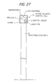
- FIG. 27 is an explanation drawing conceptually showing an example of an active noise insulation wall having such an active acoustic control cell.
- a plurality of the active acoustic control cells A are disposed on an upper end surface of a noise insulation wall B, a vertical wall, along a longitudinal direction of the noise insulation wall B.
- the active acoustic control cell A has a structure in which a speaker 2 being a sound wave generator, an amplifier 3, a skin material 4, a microphone 5 being a sound detector, and a control circuit 6 are integrated into a casing 1.
- the speaker 2 is opposed to the skin material 4 so that a sound wave generated by the speaker 2 is incident on the skin material 4.
- the microphone 5 is installed at a position between the skin material 4 and the speaker 2.
- the speaker 2 outputs an electric signal corresponding to a sound wave detected by the microphone 5.
- the control circuit 6 Based on the electric signal, the control circuit 6 performs predetermined computation, and issues a control signal obtained thereby to the amplifier 3.
- the amplifier 3 sends a drive signal corresponding to the control signal to the speaker 2.
- the speaker 2 generates a sound wave corresponding to the drive signal.
- Transfer characteristics G based on the characteristics of the speaker 2, amplifier 3, microphone 5 and control circuit 6 is adjusted to negative infinity or a value close to negative infinity, or -1, or a value close to -1, so that control is performed over a broad range of frequencies .
- the control circuit 6 stores a pattern of the transfer characteristics G at each frequency, performs required computations in response to electric signals sent from the microphone 5, and feeds predetermined control signals to the amplifier 3.
- the transfer characteristics G is controlled in this manner.
- P the sound pressure acting on the microphone 5
- Pc a control sound pressure produced by the speaker 2
- Pc G ⁇ P holds.
- the sound pressure of a diffracted sound originating from a noise source e.g., a driveway side
- an opposite side of the noise insulation wall B e.g., a private house side
- FIG. 27 shows an example of only one row of the active acoustic control cells A disposed along the noise insulation wall B.
- the number of rows of the active acoustic control cells A can be determined, as desired, according to the level of the noise to be decreased.
- FIG. 28 shows, in this type of active noise insulation wall, three of the active acoustic control cells A are arranged in a horizontal direction perpendicular to a longitudinal direction of the noise insulation wall B, without spacing between the adjacent active acoustic control cells.
- the active noise insulation wall in the active noise insulation wall according to the earlier technologies, as described above, it induces a cost increase to broaden the frequency band targeted by the active acoustic control cell, or to provide a plurality of the active acoustic control cells. That is, the conventional active noise insulation wall is not sufficient for reducing nose effectively at a low cost.
- the present invention has been accomplished in consideration of the above-described problems with the earlier technologies. It is the object of the invention to provide an active sound reduction apparatus which can reduce noise rationally at a low cost, and which can reduce not only a diffracted sound, but also a sound directly transmitted from a noise source, and an active noise insulation wall having the active sound reduction apparatus.
- the present invention which attains the above object, is characterized by the following aspects:
- FIGS. 1(a) and 1(b) are explanation drawings conceptually showing, in a partly extracted form, a first embodiment, in which FIG. 1(a) shows one sound tube, and FIG. 1(b) shows two sound tubes.
- an active acoustic control cell A1 has the same configuration and function as those of the active acoustic control cell A illustrated in FIG. 27 . That is, the active acoustic control cell A1 decreases a diffracted sound pressure component (at the relevant site) of a coming noise by active means.
- the active acoustic control cell A1 in the present embodiment is combined with a sound tube D1 or sound tubes D1, D2 to constitute a composite active sound reduction apparatus C1.
- the sound tubes D1 and D2 are different in length.
- a plurality of the active sound reduction apparatuses C1 are disposed in a row on an upper end surface of a noise insulation wall B1, a vertical wall, along a longitudinal direction of the noise insulation wall B1.
- the left side in the drawing is a noise source side, e.g., a driveway side, while the right side in the drawing is, for example, a private house side.
- the active sound reduction apparatus C1 is constituted by placing the one sound tube D1 or the plurality of sound tubes D1, D2 adjacently to the active acoustic control cell A1 on a side opposite to the source of noise to be reduced.
- the sound tubes D1, D2 have lengths which are nearly 1/4 of wavelengths other than a control target frequency of the active acoustic control cell A1.
- the sound tubes D1, D2 reduce noise of a frequency component different from that of the active acoustic control cell A1.
- FIG. 1(a) shows one sound tube, D1, disposed adjacent to the active acoustic control cell A1 on the side opposite to the noise source.
- FIG. 1(b) shows two sound tubes, D1 and D2, disposed adjacent to the active acoustic control cell A1 on the side opposite to the noise source.
- the active acoustic control cell A1 can effectively reduce noise of a specific frequency and a frequency component close to the specific frequency, while the sound tube D1 or the sound tubes D1, D2 can also reduce noises of specific frequencies defined by their lengths, and noises of frequency components close to the specific frequencies. That is, the active acoustic control cell A1 and the sound tube D1 or the sound tubes D1, D2 function compositely in reducing noises, and can effectively reduce noises in a broad frequency region. By restricting the frequency band which the active acoustic control cell is responsible for, the cost can be decreased.
- C the sound velocity (m/s).
- f 531 (Hz).
- a sound wave of a frequency of about 531 to 1,000 (Hz) is targeted, and its sound pressure can be decreased.
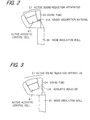
- FIG. 2 is an explanation drawing conceptually showing, in a partly extracted form, a second embodiment.
- a sound tube D3 of an active sound reduction apparatus C1 in the present embodiment has a structure in which a sound absorption material 11A is disposed at the bottom of the sound tube D1 shown in FIG. 1 .
- This structure is designed to avoid an amplifying effect on a sound wave corresponding to a length which is nearly a half of a wavelength of a sound wave whose sound pressure is decreased by the sound tube D3. That is, the sound absorption material 11A satisfactorily absorbs the above sound wave corresponding to the nearly half length, and a sound wave of a frequency close to the sound wave.
- FIG. 3 is an explanation drawing conceptually showing, in a partly extracted form, a third embodiment.
- a sound tube D4 of an active sound reduction apparatus C1 in the present embodiment has a structure in which an acoustic resistor 12A, such as a porous plate, is disposed midway through the sound tube D1 illustrated in FIG. 1 .
- This structure is designed to avoid an amplifying effect on a sound wave corresponding to a length which is nearly a half of a wavelength of a sound wave whose sound pressure is decreased by the sound tube D4. That is, the acoustic resistor 12A satisfactorily decreases the above sound wave corresponding to the nearly half length, and a sound wave of a frequency close to the sound wave.
- FIG. 4(a) is an explanation drawing conceptually showing, in a partly extracted form, a fourth embodiment.
- a sound tube D5 of an active sound reduction apparatus C1 in the present embodiment has a structure in which an acoustic resonator 13A is provided in a form continued from the bottom of the sound tube D1 shown in FIG. 1 .
- This structure is designed to avoid an amplifying effect on a sound wave corresponding to a length which is nearly a half of a wavelength of a sound wave whose sound pressure is decreased by the sound tube D5. That is, the acoustic resonator 13A satisfactorily decreases the sound pressure of the above sound wave corresponding to the nearly half length, and a sound wave of a frequency close to the sound wave.
- FIG. 5 is an explanation drawing conceptually showing, in a partly extracted form, a fifth embodiment.
- the present embodiment is a modification of the embodiment illustrated in FIGS. 4(a) and 4(b) , namely, the modification in which the sound tube D5 in the fourth embodiment shown in FIGS. 4(a) and 4(b) is omitted, and an acoustic resonator 13C is disposed directly on the surface.
- the acoustic resonator 13C minimizes the sound pressure of a sound wave of a specific frequency at a site near its entrance, thereby decreasing the sound wave of the frequency. Since the acoustic resonator is used, the frequency to be decreased can be controlled arbitrarily even in a limited space.
- the frequency of the sound wave that can be decreased by the acoustic resonator 13C is determined by the aforementioned Equation 2.
- the present embodiment is characterized in that its active sound reduction apparatus can be produced at a low cost, in comparison with a tenth embodiment to be described later on.
- the active sound reduction apparatus C1 having only one active acoustic control cell A1 is used.
- the single active acoustic control cell A1 is not restrictive, and the number of the active acoustic control cells A1 may be two or more.
- Embodiments involving two active acoustic control cells will be described as sixth to twelfth embodiments.
- FIG. 6 is an explanation drawing conceptually showing an active sound reduction apparatus C2 disposed on a noise insulation wall B1, the active sound reduction apparatus C2 having two active acoustic control cells.
- the active sound reduction apparatus C2 in the present embodiment has the active acoustic control cell A1 illustrated in FIG. 1(b) , and another active acoustic control cell A2 disposed adjacent to the sound tube D2 on its side opposite to a noise source.
- the additional active acoustic control cell A2 may be designed to decrease the frequency of a sound wave which is different from those of the active acoustic control cell A1 on the noise source side and the sound tubes D1, D2.
- the active acoustic control cells A1, A2 can effectively reduce noises of frequencies specific to them, and noises of frequency components close to the specific frequencies. Furthermore, the sound tubes D1, D2 can reduce noises of specific frequencies defined by their lengths, and noises of frequency components close to the specific frequencies. That is, the active acoustic control cells A1, A2 and the sound tubes D1, D2 exhibit composite functions in reducing noises. Thus, they can effectively reduce noises in a broader frequency region than that in the first embodiment having the single active acoustic control cell A1, and can enhance a noise reducing effect.
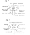
- FIG. 7 is an explanation drawing conceptually showing, in a partly extracted form, a seventh embodiment.
- sound tubes D3, D6 of an active sound reduction apparatus C2 in the present embodiment have structures in which sound absorption materials 11A, 11B are disposed at the bottom of the sound tubes D1, D2 shown in FIG. 6 .
- These structures are designed to avoid an amplifying effect on sound waves corresponding to lengths which are nearly a half of wavelengths of sound waves whose sound pressures are decreased by the sound tubes D3, D6. That is, the sound absorption materials 11A, 11B satisfactorily absorb the above sound waves corresponding to the nearly half lengths, and sound waves of frequencies close to the sound waves.
- FIG. 8 is an explanation drawing conceptually showing, in a partly extracted form, an eighth embodiment.
- sound tubes D4, D7 of an active sound reduction apparatus C2 in the present embodiment have structures in which acoustic resistors 12A, 12B, such as porous plates, are disposed midway through the sound tubes D1, D2 shown in FIG. 6 .
- These structures are designed to avoid an amplifying effect on sound waves corresponding to lengths which are nearly a half of wavelengths of sound waves whose sound pressures are decreased by the sound tubes D4, D7. That is, the acoustic resistors 12A, 12B satisfactorily decrease the above sound waves corresponding to the nearly half lengths, and sound waves of frequencies close to the sound waves.
- FIG. 9 is an explanation drawing conceptually showing, in a partly extracted form, a ninth embodiment.
- sound tubes D5, D8 of an active sound reduction apparatus C2 in the present embodiment have structures in which acoustic resonators 13A, 13B are provided in a form continued from the bottom of the sound tubes D1, D2 shown in FIG. 6 .
- These structures are designed to avoid an amplifying effect on sound waves corresponding to lengths which are nearly a half of wavelengths of sound waves whose sound pressures are decreased by the sound tubes D5, D8. That is, the acoustic resonators 13A, 13B satisfactorily decrease the sound pressures of the above sound waves corresponding to the nearly half lengths, and sound waves of frequencies close to these sound waves .
- the frequency f of the sound wave that can be decreased by the acoustic resonator 13B can also be determined by the same equation as for the acoustic resonator 13A.
- FIG. 10 is an explanation drawing conceptually showing, in a partly extracted form, a tenth embodiment.
- acoustic resonators 13C, 13D of an active sound reduction apparatus C2 in the present embodiment are directly disposed on the surface of the apparatus.
- the acoustic resonators 13C, 13D minimize the sound pressures of sound waves of specific frequencies at sites near their entrances, thereby decreasing the sound waves of the frequencies. Since the acoustic resonators are used, the frequencies to be decreased can be controlled arbitrarily even in limited spaces.
- the frequency f of the sound wave that can be decreased by the acoustic resonator 13D can be determined by the same equation (see Equation 2) as for the acoustic resonator 13C.
- the present embodiment is characterized in that noises of two different types of frequencies, other than those which can be decreased by an active sound reduction apparatus, can be reduced in comparison with the fifth embodiment.
- FIG. 11 is an explanation drawing conceptually showing, in a partly extracted form, an eleventh embodiment.
- a sound tube D9 of an active sound reduction apparatus C2 in the present embodiment has a bottom portion buried in a depression formed in an upper surface of a noise insulation wall B1.
- the length of the sound tube D9 is determined by the wavelength of a sound wave which is decreased by this sound tube, as stated above.
- the lower the frequency of a sound wave to be decreased the longer the sound tube D9 is.
- FIG. 12 is an explanation drawing conceptually showing, in a partly extracted form, a twelfth embodiment.
- the present embodiment is an embodiment in which the shape of a noise insulation wall having an active sound reduction apparatus C2 disposed thereon is different.
- a noise insulation wall B2 has an upper portion inclined toward a noise source (leftward in the drawing).
- the active sound reduction apparatus C2 is mounted on the noise insulation wall B2 with the use of this inclined surface.
- a sound absorption material may be disposed on a side surface of the noise insulation wall B2 on the noise source side.
- FIG. 13 is an explanation drawing conceptually showing, in a partly extracted form, a thirteenth embodiment.
- the present embodiment is an embodiment in which the shape of a noise insulation wall having an active sound reduction apparatus C2 disposed thereon is different.
- a noise insulation wall B3 has an upper portion branched to form an inclined surface B31 inclined toward a noise source (leftward in the drawing) and an inclined surface B32 inclined toward a side opposite to the noise source side.
- the active sound reduction apparatus C2 is disposed between both inclined surfaces B31 and B32.
- a sound absorption material may be disposed on a side surface of the noise insulation wall B3 on the noise source side.
- FIG. 14 is an explanation drawing conceptually showing, in a partly extracted form, a fourteenth embodiment. As shown in the drawing, according to the present embodiment, the whole of an active sound reduction apparatus C2 is tiltable about a turn portion O as a turn center.
- a noise insulation region can be adjusted, because the shape and the angle of inclination of the active sound reduction apparatus C2 determine a region in which the sound pressure of a diffracted wave can be decreased by the active sound reduction apparatus C2.
- the active sound reduction apparatuses used in the active noise insulation walls need not be limited to the active sound reduction apparatuses C1, C2.
- the active sound reduction apparatus can be constituted by disposing one sound tube or a plurality of sound tubes adjacent to the active acoustic control cell on its side facing a noise source as a target of sound reduction (e.g., a driveway side), or on its side opposite to the noise source, or on both of the noise source side and the opposite side of the active acoustic control cell.
- the number of the active acoustic control cells need not be restricted to one or two, and the active sound reduction apparatus having various combinations of the active acoustic control cells can be constituted.
- Each sound tube in each active sound reduction apparatus has a length which is nearly 1/4 of a wavelength of a sound wave other than a control target frequency for the active acoustic control cell.
- the sound tube can reduce noise of a frequency component which is different from the target frequency for the active acoustic control cell.
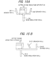
- the structure may be a structure as shown in FIG. 15(a) or 15(b) .
- a noise insulation wall B9 shown in FIG. 15(a) has an upper end portion bifurcating to form branch walls B91 and B92 extending upward.
- An active sound reduction apparatus C1 is disposed between the branch walls B91 and B92.
- branch walls B101 and B102 are both formed on a side opposite to a noise source (of course, may be on a noise source side) relative to an active sound reduction apparatus C1.
- the number of the branch walls, B101, B102 is undoubtedly not restricted to two.
- the active sound reduction apparatuses C1 or C2 are disposed only in one row on the noise insulation wall.
- a plurality of edges may be formed above the noise insulation wall, and only the active acoustic control cells A, or the active sound reduction apparatuses C1 or active sound reduction apparatuses C2 may be disposed in a plurality of rows.
- Embodiments in which only the active acoustic control cells A, or the active sound reduction apparatuses C1 or active sound reduction apparatuses C2 are disposed in a plurality of rows will be described as fifteenth to eighteenth embodiments.
- FIG. 16 is an explanation drawing conceptually showing, in a partly extracted form, a fifteenth embodiment.
- a sound insulation wall B4 according to the present embodiment has three branch walls B41, B42 and B43 extending upward from an upper end of a vertical wall, and rows made by arranging a plurality of active acoustic control cells A are formed on the upper end surfaces of the branch walls B41, B42 and B43.
- the respective rows of the active acoustic control cells A are disposed with predetermined spacing between the adjacent rows. It is not absolutely necessary to make the characteristics, size, etc. of the acoustic control cells A the same, and their characteristics and sizes may be freely combined.
- the three branch walls B41, B42 and B43 in the present embodiment may have upper surfaces different in height position. That is, there is no restriction on the height positions of their upper surfaces.
- the cost of the active noise insulation wall can be decreased, without a marked deterioration of the sound reducing effect, in comparison with the active acoustic control cells A being arranged without spacing between the adjacent rows. That is, the inventors of the present invention have found that the sound reducing effect is greater when the active acoustic control cells A are arranged in rows with spacing between the rows in a direction perpendicular to a longitudinal direction of the noise insulation wall B, than when the active acoustic control cells A are arranged in rows adjacently without spacing between the rows. The present embodiment is based on this finding.
- Providing the plural rows with predetermined spacing can obtain a more satisfactory sound reducing effect than providing the plural rows contiguously (i.e. adjacently with no spacing).
- the number of the active acoustic control cells can be decreased, compared with the disposition of the active acoustic control cells such that all of the adjacent spaces are filled with the active acoustic control cells.
- the spaced provision of the plural rows can contribute to a decreased cost.
- FIG. 17 is an explanation drawing conceptually showing, in a partly extracted form, a sixteenth embodiment.
- the present embodiment is a modification of the thirteenth embodiment shown in FIG. 13 .
- a noise insulation wall B5 has two branch walls B51 and B52 extending upward from an upper end of a vertical wall, and two active sound reduction apparatuses C1 are disposed with spacing on both branch walls B51 and B52 of the noise insulation wall B5.
- the wavelength of a sound wave to be decreased lengthens a greater spacing between the active sound reduction apparatuses C1 proves more effective.
- the present embodiment involves a replacement of the active acoustic control cells A by the active sound reduction apparatuses C1.
- a more satisfactory sound reducing effect can be obtained than when plural rows of the active sound reduction apparatuses C1 are disposed contiguously without spacing between the adjacent rows.
- the number of the active sound reduction apparatuses can be decreased, compared with the disposition of the active sound reduction apparatuses such that all of the adjacent spaces are filled with the active sound reduction apparatuses.
- the spaced provision of the plural rows can contribute to a decreased cost.
- FIG. 18 is an explanation drawing conceptually showing, in a partly extracted form, a seventeenth embodiment.
- the present embodiment is a modification of the sixteenth embodiment shown in FIG. 17 .
- a noise insulation wall B6 has a widened portion B61 in an upper end portion thereof, the widened portion B61 expanding in a direction perpendicular to the longitudinal direction of the noise insulation wall B6.
- Two active sound reduction apparatuses C1 are disposed with spacing on the widened portion B61.
- the active sound reduction apparatus C1 is movable on the widened portion B61, so that the distance between the active sound reduction apparatuses C1 can be freely adjusted.
- the present embodiment also functions like the sixteenth embodiment. According to the present embodiment, moreover, the position of the active sound reduction apparatus C1 on the widened portion B61 can be adjusted. Thus, such a distance between both active sound reduction apparatuses C1 as will obtain optimal sound reducing effect can be easily secured. Furthermore, the area occupied in an installation place on a road or the like can be easily adjusted. Depending on a highway or an ordinary road, there may be a restriction on an installation area where the active noise insulation wall can be used.
- FIG. 19 is an explanation drawing conceptually showing, in a partly extracted form, an eighteenth embodiment.
- the present embodiment is a modification of the sixteenth embodiment shown in FIG. 17 .
- a noise insulation wall B7 has support portions B71, B72 in an upper end portion thereof, the support portions B71, B72 having base ends supported by a turn portion O so as to be rotatable normally and reversely.
- Active sound reduction apparatuses C1 are mounted on the support portions B71 and B72.
- both active sound reduction apparatuses C1 integrally rotate in accordance with the normal or reverse rotation of the support portions B71, B72, so that the distance between them can be increased or decreased.
- the active sound reduction apparatuses C1 may be provided with separate turn portions, and mounted to the support portions B71 and B72 so as to be normally or reversely rotatable. In this case, when the support portions B71, B72 open or close upon their normal or reverse rotation, the angle of installation of the active sound reduction apparatus C1 relative to the installation surface (ground surface) can be independently adjusted to a preferred angle, such as a constant angle.
- the present embodiment also functions like the sixteenth embodiment. According to the present embodiment, moreover, the distance between the active sound reduction apparatuses C1 can be easily adjusted by rotating the support portions B71, B72 normally or reversely. Thus, such a distance between both active sound reduction apparatuses C1 as will obtain optimal sound reducing effect can be easily secured. Furthermore, the area occupied in an installation place on a road or the like can be easily adjusted. Depending on a highway or an ordinary road, there may be a restriction on an installation area where the active noise insulation wall can be used.
- the active sound reduction apparatuses used in the active noise insulation walls according to the fifteenth to eighteenth embodiments may be any of the active sound reduction apparatuses usable in the first to fourteenth embodiments.
- noise insulation walls used in the active noise insulation walls there is no restriction on the structure of the noise insulation walls used in the active noise insulation walls according to the fifteenth to eighteenth embodiments, i.e., the noise insulation walls combined with the active sound reduction apparatuses.
- a noise insulation wall B11 shown in FIG. 20 has an upper end portion trifurcating to form branch walls B111, B112 and B113 extending upward.
- An active sound reduction apparatus C1 is disposed on each of the branch walls B111 and B112, as in the embodiment shown in FIG. 17 .
- no active sound reduction apparatus C1 is disposed on the branch wall B113.
- the sound tubes of the active sound reduction apparatuses C1 were all the sound tubes D1, but they are not limited to the sound tubes D1.
- the sound tubes can be selected arbitrarily depending on the frequency to be decreased.
- the active sound reduction apparatus may be formed of only the active sound reduction apparatus C1 having the sound tube D2.
- one of the right and left active sound reduction apparatuses C1 may be formed of the active sound reduction apparatus C1 having the sound tube D1
- the other active sound reduction apparatus C1 may be formed of the active sound reduction apparatus C1 having the sound tube D2.
- the active sound reduction apparatuses C1 having various sound tubes may be combined as desired.
- FIG. 21 is an explanation drawing conceptually showing, in a partly extracted form, a nineteenth embodiment.
- the present embodiment is a modification of the fifteenth embodiment shown in FIG. 16 .
- a noise insulation wall B8 has an upper end portion branching to form an inclined surface B81 inclined toward a noise source side (left side in the drawing), and an inclined surface B82 inclined toward a side opposite to the noise source side.
- Active acoustic control cells A are disposed on the upper end surfaces of the inclined surfaces B81 and B82 of the noise insulation wall B8.
- a noise killer cell E1 is provided on the inclined surface B81 to reduce noise travelling rectilinearly from the noise source past the end of the active acoustic control cell A on the inclined surface B81 (the upper end of the active noise insulation wall) (i.e., noise running along a virtual axis Y indicated by a one-dot chain line in FIG. 21 ).
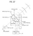
- FIG. 22 is an explanation drawing conceptually showing the noise killer cell E1 in a partly extracted form.
- the noise killer cell E1 has a microphone 21 and a speaker 22 placed on the virtual axis Y connecting a noise source 20 and the upper end portion of the noise insulation wall B.
- the microphone 21 detects noise emitted from the noise source 20, while the speaker 22 emits a noise killer sound in a direction opposite to the direction of the noise source 20.
- the microphone 21 and the speaker 22 are housed in an enclosure 23 and mounted on the noise insulation wall B via the enclosure 23.
- a side of the enclosure 23 facing the noise source 20 is covered with a backing plate 23a, while a side of the enclosure 23 opposite to the noise source 20 is open for issuing a noise killer sound produced by the speaker 22.
- the speaker 22 is attached to a baffle plate 23b, and housed in the enclosure 23.
- the microphone 21 is attached to nearly the center of the backing plate 23a. An output of the microphone 21 is fed to a computation unit 24, which performs a predetermined computation to feed an output signal to the speaker 22.
- FIG. 23 is a block diagram of the noise killer cell E1.
- the computation unit 24 is basically composed of a deviation computation section 35 for computing a deviation between a voltage proportional to a sound pressure, an output signal of a target sound pressure setting section 34 for generating a voltage proportional to a target sound pressure (normally, nearly zero), and a voltage proportional to noise detected by the microphone 21; and a control section 36 for generating a noise killer sound, which has a sound pressure identical with and a phase opposite to, the sound pressure and phase of noise at certain points on a line segment connecting the noise insulation wall B and the speaker 22, based on the deviation computed by the deviation computation section 35.
- the noise killer sound is emitted by the speaker 22.
- a synthesis sound combined from the noise and the noise killer sound has a sound pressure, at the certain points on the line segment connecting the upper end portion of the noise insulation wall B and the speaker 22, of nearly zero.
- propagation of the noise from such points to the outside can be prevented.
- a sound pressure in a region to be actually muffled may be detected by another microphone 37 for monitoring, and a control parameter of the control section 36 may be computed by a separately provided adaptive control section 38 based on the sound pressure in the region to be actually muffled and the deviation computed by the deviation computation section 35. In this case, the output of the control section 36 is fed back to the target sound pressure setting section 34 to adjust the target sound pressure.
- the active acoustic control cells A disposed in two rows can reduce noise leaking to areas below the noise insulation wall B8, namely, a diffracted sound
- the noise killer cells E1 can reduce noise diffusing to areas above the noise insulation wall B8, namely, a rectilinearly travelling sound. Consequently, satisfactory noise reduction can be achieved in a wide range, including areas above the noise insulation wall B8.
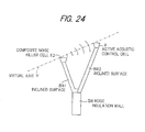
- FIG. 24 is an explanation drawing conceptually showing, in a partly extracted form, a twentieth embodiment.
- the present embodiment is a modification of the nineteenth embodiment shown in FIG. 21 . That is, a composite noise killer cell E2 is disposed instead of the active acoustic control cell A of the embodiment shown in FIG. 21 .
- the composite noise killer cell E2 has the functions of the active acoustic control cell A and the noise killer cell E1.
- FIG. 25 is an explanation drawing conceptually showing the composite noise killer cell E2 in an extracted form.
- the composite noise killer cell E2 has a microphone 21, a speaker 22 and a computation unit 24 which function in the same manner as in the noise killer cell E1.
- another microphone 25 is provided ahead of the speaker 22 to measure the sound pressure of noise leaking to the outside after diffracting at the noise insulation wall B.
- the output signal of the microphone 25 is subjected to a predetermined computation by a computation unit 26.
- An electric signal based on the results of this computation drives the speaker 22 via a mixer 27 and an amplifier 28.
- the computation unit 26 drives the speaker 22 so that the sound pressure at the microphone 25 is reduced to zero. That is, the microphone 25, computation unit 26 and speaker 22 act integrally as an active acoustic control cell as well.
- the mixer 27 mixes signals computed by the computation units 24 and 26, so that the speaker 22 is driven by the resulting mixed signal.
- a sound wave produced by the speaker 22 can interfere with a sound wave, which travels rectilinearly from a noise source 20 past an upper end portion of the noise insulation wall B and diffuses to the outside, to decrease the sound wave, and can also decrease a diffracted wave diffracting at the noise insulation wall B and leaking to the outside.
- noise passing beside the upper end portion of the active noise insulation wall and travelling rectilinearly i.e., noise travelling along a virtual axis Y indicated by a one-dot chain line in FIG. 25
- the rectilinear wave decreasing function of the composite noise killer cell E2 Furthermore, sound waves leaking as diffracted waves can be decreased by the diffracted sound reducing function of the composite noise killer cell E2 and the function of the active acoustic control cell A. That is, satisfactory noise reduction can be achieved in a wide range, including areas above the noise insulation wall B8, in the same manner as in the nineteenth embodiment.
- the noise killer cell E1 and the composite noise killer cell E2 can be combined with the first to sixteenth embodiments and all of their modifications. Any of these combinations can reduce diffracted sounds, and noises travelling rectilinearly from the noise source and leaking to the outside of the noise insulation wall.
- the noise killer cell E1 is designed to actively reduce noise travelling rectilinearly from the noise source, but may be a passive reducer.
- a passive noise killer cell E3 can be constituted, for example, from an interference type muffler as shown in FIG. 26 . As illustrated in FIG. 26 , the noise killer cell E3 is composed of sound tubes 31, 32, 33, tubes through which sound waves of lengths 1 1 , 1 2 and 1 3 pass.
- 1 1 ⁇ 1 2 ⁇ 1 3 and the sound tubes 32 and 33 at lower positions have progressively increasing lengths.
- the active sound reduction apparatuses used in the active noise insulation walls according to the nineteenth to twentieth embodiments may be any combinations of the active sound reduction apparatuses usable in the first to fourteenth embodiments. If there are a plurality of rows other than rows formed from the noise killer cells E1, E3 or the composite noise killer cells E2, active sound reduction apparatuses of different types may, of course, be disposed in respective rows.
- the noise insulation wall used in the active noise insulation wall according to the nineteenth or twentieth embodiment i.e., the noise insulation wall combined with the noise killer cell.
- the noise insulation wall used in the active noise insulation wall according to the nineteenth or twentieth embodiment, i.e., the noise insulation wall combined with the noise killer cell.
- FIG. 20 there may be a branch wall acting as a mere noise insulation wall on which the noise killer cell E1 or the like is not disposed.
- a sound reducing function at a portion corresponding to the branch wall B113 is added, so that more effective noise insulation can be performed.
Landscapes
- Engineering & Computer Science (AREA)
- Physics & Mathematics (AREA)
- Acoustics & Sound (AREA)
- Multimedia (AREA)
- Architecture (AREA)
- Civil Engineering (AREA)
- Structural Engineering (AREA)
- Devices Affording Protection Of Roads Or Walls For Sound Insulation (AREA)
- Soundproofing, Sound Blocking, And Sound Damping (AREA)
- Building Environments (AREA)
Abstract
Description
- The entire disclosure of Japanese Patent Application No.
2001-18315 filed on January 26, 2001 - This invention relates to an active sound reduction apparatus, and an active noise insulation wall having it. More specifically, the invention relates to them which are laid along highways, ordinary roads, and railways, and which are useful in insulating noises caused by travelling vehicles, trains, etc. as sound sources.
- To insulate noise from a sound source, such as a vehicle or a train travelling on a highway, an ordinary road, or a railway, a noise insulation wall is erected along such a highway or the like. In recent years, an active acoustic control cell has been developed as an effective insulator of noise produced in such a case. The active acoustic control cell senses a sound from a sound source by a microphone, and processes an electric signal based thereon to generate a sound from a speaker so that a sound pressure at a predetermined position is reduced to zero, thereby reducing noise which is propagated after diffraction from the sound source to the outside of a noise insulation wall. That is, this type of active acoustic control cell is disposed on an upper end surface of the noise insulation wall, a vertical wall provided along a road or the like. This active acoustic control cell performs control in such a manner as to decrease a diffracted sound pressure component (at the upper end surface) of coming noise by active means (see, for example, Japanese Unexamined Patent Publication No.
1997-119114 -
FIG. 27 is an explanation drawing conceptually showing an example of an active noise insulation wall having such an active acoustic control cell. As shown in the drawing, a plurality of the active acoustic control cells A are disposed on an upper end surface of a noise insulation wall B, a vertical wall, along a longitudinal direction of the noise insulation wall B. The active acoustic control cell A has a structure in which aspeaker 2 being a sound wave generator, anamplifier 3, askin material 4, amicrophone 5 being a sound detector, and acontrol circuit 6 are integrated into acasing 1. Thespeaker 2 is opposed to theskin material 4 so that a sound wave generated by thespeaker 2 is incident on theskin material 4. Themicrophone 5 is installed at a position between theskin material 4 and thespeaker 2. Thus, thespeaker 2 outputs an electric signal corresponding to a sound wave detected by themicrophone 5. Based on the electric signal, thecontrol circuit 6 performs predetermined computation, and issues a control signal obtained thereby to theamplifier 3. Theamplifier 3 sends a drive signal corresponding to the control signal to thespeaker 2. Thespeaker 2 generates a sound wave corresponding to the drive signal. Transfer characteristics G based on the characteristics of thespeaker 2,amplifier 3,microphone 5 andcontrol circuit 6 is adjusted to negative infinity or a value close to negative infinity, or -1, or a value close to -1, so that control is performed over a broad range of frequencies . That is , thecontrol circuit 6 stores a pattern of the transfer characteristics G at each frequency, performs required computations in response to electric signals sent from themicrophone 5, and feeds predetermined control signals to theamplifier 3. The transfer characteristics G is controlled in this manner. Thus, if the sound pressure acting on themicrophone 5 is designated as P, and a control sound pressure produced by thespeaker 2, as Pc, then Pc = G·P holds. As a result, the sound pressure of a diffracted sound originating from a noise source (e.g., a driveway side), changing in direction at the upper end surface of the noise insulation wall B upon diffraction, and leaking to an opposite side of the noise insulation wall B (e.g., a private house side) can be decreased. -
FIG. 27 shows an example of only one row of the active acoustic control cells A disposed along the noise insulation wall B. There is no restriction on the number of rows of the active acoustic control cells A. The number of rows of the active acoustic control cells A can be determined, as desired, according to the level of the noise to be decreased. An active noise insulation wall according to an earlier technology, having three rows of the active acoustic control cells A disposed thereon, is shown inFIG. 28 . As the drawing shows, in this type of active noise insulation wall, three of the active acoustic control cells A are arranged in a horizontal direction perpendicular to a longitudinal direction of the noise insulation wall B, without spacing between the adjacent active acoustic control cells. - In the active noise insulation wall according to the earlier technologies, as described above, it induces a cost increase to broaden the frequency band targeted by the active acoustic control cell, or to provide a plurality of the active acoustic control cells. That is, the conventional active noise insulation wall is not sufficient for reducing nose effectively at a low cost.
- The present invention has been accomplished in consideration of the above-described problems with the earlier technologies. It is the object of the invention to provide an active sound reduction apparatus which can reduce noise rationally at a low cost, and which can reduce not only a diffracted sound, but also a sound directly transmitted from a noise source, and an active noise insulation wall having the active sound reduction apparatus.
- The present invention, which attains the above object, is characterized by the following aspects:
- 1) An active sound reduction apparatus having an active acoustic control cell, disposed on an upper end surface of a noise insulation wall, for controlling a coming noise such that a diffracted sound pressure component of the coming noise at the upper end surface is actively reduced; and one sound tube or a plurality of sound tubes of a length which is nearly 1/4 of a wavelength or wavelengths of one sound wave or a plurality of sound waves other than a control target frequency of the active acoustic control cell, the one sound tube or the plurality of sound tubes being provided on a side of the active acoustic control cell facing a sound source to be subjected to sound reduction, or on a side of the active acoustic control cell opposite to the sound source, or on both of the sound source side and the opposite side of the active acoustic control cell.
According to this aspect, sound waves of frequencies different between the active acoustic control cell and the sound tube(s) can be decreased. Thus, noises including a wide range of frequency components can be reduced effectively. - 2) The active sound reduction apparatus of the aspect 1), wherein a sound absorption material is disposed at a bottom of the sound tube to avoid an amplifying effect on a sound wave corresponding to a length which is nearly a half of a wavelength of a sound wave whose sound pressure is decreased by the sound tube.
According to this aspect, the sound tube decreases a sound wave of a frequency natural to the sound tube, while the sound absorption material absorbs a sound wave of a hazardous frequency deteriorating this sound wave decreasing effect. Thus, the aspect 2) can reduce noises, including a broad range of frequency components, more effectively than the aspect 1). - 3) The active sound reduction apparatus of the aspect 1), wherein an acoustic resistor, such as a porous plate, is disposed inside the sound tube to avoid an amplifying effect on a sound wave corresponding to a length which is nearly a half of a wavelength of a sound wave whose sound pressure is decreased by the sound tube.
According to this aspect, the sound tube decreases a sound wave of a frequency natural to the sound tube, while the acoustic resistor decreases a sound wave of a hazardous frequency deteriorating this sound wave decreasing effect. Thus, the aspect 3) can reduce noises, including a broad range of frequency components, more effectively than the aspect 1). - 4) The active sound reduction apparatus of the aspect 1), wherein an acoustic resonator is disposed inside the sound tube to avoid an amplifying effect on a sound wave corresponding to a length which is nearly a half of a wavelength of a sound wave whose sound pressure is decreased by the sound tube.
According to this aspect, the sound tube decreases a sound wave of a frequency natural to the sound tube, while the acoustic resonator decreases a sound wave of a hazardous frequency deteriorating this sound wave decreasing effect. Thus, the aspect 4) can reduce noises, including a broad range of frequency components, more effectively than the aspect 1). - 5) An active sound reduction apparatus having an active acoustic control cell, disposed on an upper end surface of a noise insulation wall, for controlling a coming noise such that a diffracted sound pressure component of the coming noise at the upper end surface is actively reduced; and one acoustic resonator or a plurality of acoustic resonators tuned to a frequency or frequencies other than a control target frequency of the active acoustic control cell in order to decrease a sound pressure at the frequency or frequencies, the one acoustic resonator or the plurality of acoustic resonators being provided on a side of the active acoustic control cell facing a sound source to be subjected to sound reduction, or on a side of the active acoustic control cell opposite to the sound source, or on both of the sound source side and the opposite side of the active acoustic control cell.
According to this aspect, the sound pressure at a specific frequency other than the control frequency of the active acoustic control cell can also be decreased by the acoustic resonator(s). Thus, the aspect 5) can achieve satisfactory reduction of coming noise by the combined sound pressure decreasing function of the active acoustic control cell and the acoustic resonator(s). - 6) An active sound reduction apparatus comprising a plurality of the active sound reduction apparatuses of the aspect 1) combined together.
According to this aspect, a plurality of the active acoustic control cells exhibit respective sound reducing functions. Thus, the aspect 6) can reduce noises, including a broad range of frequency components, more effectively than the aspect 1). - 7) An active sound reduction apparatus comprising a plurality of the active sound reduction apparatuses of the aspect 2) combined together.
According to this aspect, a plurality of the active acoustic control cells exhibit respective sound reducing functions. Thus, the aspect 7) can reduce noises, including a broad range of frequency components, more effectively than the aspect 2). - 8) An active sound reduction apparatus comprising a plurality of the active sound reduction apparatuses of the aspect 3) combined together.
According to this aspect, a plurality of the active acoustic control cells exhibit respective sound reducing functions. Thus, the aspect 8) can reduce noises, including a broad range of frequency components , more effectively than the aspect 3). - 9) An active sound reduction apparatus comprising a plurality of the active sound reduction apparatuses of the aspect 4) combined together.
According to this aspect, a plurality of the active acoustic control cells exhibit respective sound reducing functions. Thus, the aspect 9) can reduce noises, including a broad range of frequency components, more effectively than the aspect 4). - 10) An active sound reduction apparatus comprising a plurality of the active sound reduction apparatuses of the aspect 5) combined together.
According to this aspect, a plurality of the active acoustic control cells exhibit respective sound reducing functions. Thus, the aspect 10) can reduce noises, including a broad range of frequency components, more effectively than the aspect 5). - 11) An active noise insulation wall comprising a plurality of the active sound reduction apparatuses of any one of the aspects 1) to 10), the active sound reduction apparatuses being disposed in a row along a longitudinal direction of an upper end surface of a noise insulation wall or a side surface of an upper portion of the noise insulation wall.
According to this aspect, sound waves of frequencies different between the active acoustic control cell and the sound tube(s) can be decreased. Thus, the aspect 11) can effectively reduce noises, including a wide range of frequency components, so that the function of the noise insulation wall can be improved. - 12) The active noise insulation wall of the aspect 11), wherein the active sound reduction apparatuses are mounted on an upper portion of the noise insulation wall so as to be normally and reversely rotatable in a vertical plane.
According to this aspect, a region in which a diffracted sound is decreased can be determined arbitrarily by selecting, as desired, the angles of the active sound reduction apparatuses. Thus, the aspect 12) can obtain the most potent effect of reducing noises adapted for the location of installation, by using the noise insulation wall that can effectively reduce noises, including a wide range of frequency components. - 13) The active noise insulation wall of the aspect 11), wherein at least one of the sound tubes of the active sound reduction apparatuses has a bottom portion entering a depression of an upper end portion of the noise insulation wall.
According to this aspect, an installation space for the sound tube can be secured in the noise insulation wall. Thus, the aspect 13) can decrease the bulk of the active noise insulation wall. - 14) The active noise insulation wall of any one of the aspects 11) to 13), wherein the noise insulation wall branches at an upper end portion thereof to have a plurality of branch walls extending upward, and the active sound reduction apparatus is disposed either between two of the branch walls, or on a side of one of or the plurality of the branch walls facing a noise source, or on a side thereof opposite to the noise source.
According to this aspect, individual noise insulation functions are obtained by the branch walls. Thus, the aspect 14) can achieve a better noise insulation effect because the sound reducing effect of the branch wall is added. - 15) An active noise insulation wall having a plurality of rows formed by spacing the adjacent rows by a predetermined distance, each of the rows being formed from a plurality of active acoustic control cells, disposed in a longitudinal direction of a noise insulation wall, for controlling a coming noise such that a diffracted sound pressure component of the coming noise at an upper end surface of the noise insulation wall is actively reduced.
According to this aspect, it is possible to obtain a more effective sound reducing effect than when there are provided a plurality of the rows of the active acoustic control cells disposed contiguously. Thus, the aspect 15) can achieve a satisfactory sound reducing effect by a fewer rows of the active acoustic control cells. Consequently, the active noise insulation wall can be constructed at a lower cost. - 16) An active noise insulation wall having a plurality of rows formed by spacing the adjacent rows by a predetermined distance, each of the rows being formed from a plurality of the active sound reduction apparatuses of any one of the aspects 1) to 10), which are disposed in a longitudinal direction of the noise insulation wall.
According to this aspect, it is possible to obtain a more effective sound reducing effect than when there are provided a plurality of the rows of the active sound reduction apparatuses disposed contiguously. Thus, the aspect 16) can achieve a satisfactory sound reducing effect by a fewer rows of the active sound reduction apparatuses. Consequently, the active noise insulation wall can be constructed at a lower cost. - 17) The active noise insulation wall of the aspect 15) or 16), wherein the distance between the active acoustic control cells or the active sound reduction apparatuses of the adjacent rows is adjustable.
According to this aspect, the distance between the adjacent active acoustic control cells or the adjacent active sound reduction apparatuses can be adjusted freely. Thus, the aspect 17) can easily secure an optimal spacing adapted for the installation place. - 18) The active noise insulation wall of the aspect 15) or 16), wherein each of the rows of the active acoustic control cells or the active sound reduction apparatuses is mounted on an upper end portion of the noise insulation wall so as to be normally and reversely rotatable, and an angle of normal or reverse rotation of each row is adjusted, whereby the distance between the active acoustic control cells or the active sound reduction apparatuses of the adjacent rows is adjustable.
According to this aspect, the spacing between the adjacent active acoustic control cells or active sound reduction apparatuses can be adjusted by adjusting the angle of normal or reverse rotation. Thus, the aspect 18) can easily secure an optimal spacing adapted for the installation place. - 19) The active noise insulation wall of the aspect 15) or 16), wherein noise killer cells are disposed, on one of the rows facing a noise source, for generating a sound wave interfering with a sound wave travelling rectilinearly from the noise source after passing over an upper end portion of the noise insulation wall to decrease the sound wave travelling rectilinearly.
According to this aspect, it is possible to decrease not only noise which diffracts at the upper end surface of the noise insulation wall and leaks to the outside, but also the sound wave travelling rectilinearly from the noise source, passing on the upper end surface of the noise insulation wall, and diffusing obliquely upwardly. Thus, the aspect 19) can reduce noises not only in a region below the noise insulation wall, but also in a region above the noise insulation wall, for example, a region covering an upper floor of a building. - 20) The active noise insulation wall of the aspect 15) or 16), wherein composite noise killer cells having functions of a noise killer cell and the active acoustic control cell are disposed on one of the rows facing a noise source, the noise killer cell being adapted to generate a sound wave interfering with a sound wave travelling rectilinearly from the noise source after passing over an upper end portion of the noise insulation wall to decrease the sound wave travelling rectilinearly.
According to this aspect, it is possible to decrease not only noise which diffracts at the upper end surface of the noise insulation wall and leaks to the outside, but also the sound wave travelling rectilinearly from the noise source, passing on the upper end surface of the noise insulation wall, and diffusing obliquely upwardly. Thus, the aspect 20) can reduce noises not only in a region below the noise insulation wall, but also in a region above the noise insulation wall, for example, a region covering an upper floor of a building. - 21) The active noise insulation wall of the aspect 19), wherein the noise killer cells each include noise detection means, such as a microphone, disposed on a straight line connecting the noise source to the upper end portion of the noise insulation wall, noise killer sound generation means, such as a speaker, for generating a sound wave interfering with a sound wave travelling rectilinearly along the straight line connecting the noise source to the upper end portion of the noise insulation wall to decrease the sound wave, and computation means for issuing a signal for generating a noise killer sound which is generated by the noise killer sound generation means based on noise detected by the noise detection means.
According to this aspect, the sound wave travelling rectilinearly from the noise source and diffusing to the outside of the noise insulation wall can be decreased by an active method. Thus, the aspect 21) can reduce noise in a region above the noise insulation wall satisfactorily. - 22) The active noise insulation wall of the aspect 19), wherein the noise killer cell is an interference type muffler formed by combining a plurality of sound tubes.
According to this aspect, a sound wave travelling rectilinearly from a noise source and diffusing to the outside of the noise insulation wall can be decreased by a passive method. Thus, the aspect 22) can reduce noise in a region above the noise insulation wall by a simple structure and at a low cost. - 23) The active noise insulation wall of the aspect 20), wherein the composite noise killer cells each include noise detection means, such as a microphone, disposed on a straight line connecting the noise source to the upper end portion of the noise insulation wall, one computation means for issuing a signal for generating a killer sound for noise based on the noise detected by the noise detection means, diffracted sound detection means, such as a microphone, for detecting a sound wave diffracting at the upper end portion of the noise insulation wall and leaking to an outside, other computation means for issuing a signal for generating a killer sound for a diffracted sound based on the diffracted sound detected by the diffracted sound detection means, mixing means for mixing the signal issued by the one computation means and the signal issued by the other computation means, and sound wave generation means, such as a speaker, driven by an output signal of the mixing means to generate a sound wave for decreasing both a sound wave travelling rectilinearly from the noise source and reaching the outside of the noise insulation wall, and a sound wave diffracting at the upper end portion of the noise insulation wall and reaching the outside.
According to this aspect, it is possible to decrease not only noise which diffracts at the upper end surface of the noise insulation wall and leaks to the outside, but also the sound wave travelling rectilinearly from the noise source, passing on the upper end surface of the noise insulation wall, and diffusing obliquely upwardly. Thus, the aspect 23) can reduce noise not only in a region below the noise insulation wall, but also in a region above the noise insulation wall, for example, a region covering an upper floor of a building. - 24) The active noise insulation wall of any one of the aspects 15) to 23), wherein the noise insulation wall branches at an upper end portion thereof to have a plurality of branch walls extending upward, and one of or the plurality of the branch walls is or are formed only of a branch wall or branch walls having none of the active acoustic control cell, the active sound reduction apparatus, the noise killer cell, and the composite noise killer cell disposed thereon.
According to this aspect, individual noise insulation functions are obtained by the branch walls. Thus, the aspect 24) can achieve a better noise insulation effect because the sound reducing effect of the branch wall is added. - 25) A composite noise killer cell including noise detection means, such as a microphone, disposed on a straight line connecting a noise source to an upper end portion of a noise insulation wall, one computation means for issuing a signal for generating a killer sound for noise based on the noise detected by the noise detection means, diffracted sound detection means, such as a microphone, for detecting a sound wave diffracting at the upper end portion of the noise insulation wall and leaking to an outside, other computation means for issuing a signal for generating a killer sound for a diffracted sound based on the diffracted sound detected by the diffracted sound detection means, mixing means for mixing the signal issued by the one computation means and the signal issued by the other computation means, and sound wave generation means, such as a speaker, driven by an output signal of the mixing means to generate a sound wave for decreasing both a sound wave travelling rectilinearly from the noise source and reaching the outside of the noise insulation wall, and a sound wave diffracting at the upper end portion of the noise insulation wall and reaching the outside.
According to this aspect, when the composite noise killer cell is mounted on the noise insulation wall, it can act on the diffracted sound and the rectilinear sound from the noise source to decrease both sound waves. Thus, the aspect 25) facilitates the construction of an active noise insulation wall for reducing noises not only in a region below the noise insulation wall, but also in a region above the noise insulation wall, and can contribute greatly to constructing the active noise insulation wall. - The present invention will become more fully understood from the detailed description given hereinbelow and the accompanying drawings which are given by way of illustration only, and thus are not limitative of the present invention, and wherein:
-
FIGS. 1(a) and 1(b) are explanation drawings conceptually showing, in a partly extracted form, a first embodiment, in whichFIG. 1(a) shows one sound tube, andFIG. 1(b) shows two sound tubes; -
FIG. 2 is an explanation drawing conceptually showing, in a partly extracted form, a second embodiment; -
FIG. 3 is an explanation drawing conceptually showing, in a partly extracted form, a third embodiment; -
FIGS. 4(a) and 4(b) are views showing a fourth embodiment, in whichFIG. 4(a) is an explanation drawing conceptually showing the fourth embodiment in a partly extracted form, and -
FIG. 4(b) is an explanation drawing showing an acoustic resonator of the fourth embodiment in an extracted and enlarged form; -
FIG. 5 is an explanation drawing conceptually showing, in a partly extracted form, a fifth embodiment; -
FIG. 6 is an explanation drawing conceptually showing, in a partly extracted form, a sixth embodiment; -
FIG. 7 is an explanation drawing conceptually showing, in a partly extracted form, a seventh embodiment; -
FIG. 8 is an explanation drawing conceptually showing, in a partly extracted form, an eighth embodiment; -
FIG. 9 is an explanation drawing conceptually showing, in a partly extracted form, a ninth embodiment; -
FIG. 10 is an explanation drawing conceptually showing, in a partly extracted form, a tenth embodiment; -
FIG. 11 is an explanation drawing conceptually showing, in a partly extracted form, an eleventh embodiment; -
FIG. 12 is an explanation drawing conceptually showing, in a partly extracted form, a twelfth embodiment; -
FIG. 13 is an explanation drawing conceptually showing, in a partly extracted form, a thirteenth embodiment; -
FIG. 14 is an explanation drawing conceptually showing, in a partly extracted form, a fourteenth embodiment; -
FIGS. 15(a) and 15(b) are explanation drawings conceptually showing modifications of the structure of a noise insulation wall in an active noise insulation wall; -
FIG. 16 is an explanation drawing conceptually showing, in a partly extracted form, a fifteenth embodiment; -
FIG. 17 is an explanation drawing conceptually showing, in a partly extracted form, a sixteenth embodiment; -
FIG. 18 is an explanation drawing conceptually showing, in a partly extracted form, a seventeenth embodiment; -
FIG. 19 is an explanation drawing conceptually showing, in a partly extracted form, an eighteenth embodiment; -
FIG. 20 is an explanation drawing conceptually showing a modification of the structure of a noise insulation wall in an active noise insulation wall; -
FIG. 21 is an explanation drawing conceptually showing, in a partly extracted form, a nineteenth embodiment; -
FIG. 22 is an explanation drawing conceptually showing an example of a noise killer cell used in the embodiment illustrated inFIG. 21 ; -
FIG. 23 is a block diagram showing the configuration of the noise killer cell illustrated inFIG. 22 ; -
FIG. 24 is an explanation drawing conceptually showing, in a partly extracted form, a twentieth embodiment; -
FIG. 25 is an explanation drawing conceptually showing an active acoustic control cell having composite killer functions used in the embodiment illustrated inFIG. 24 ; -
FIG. 26 is an explanation drawing conceptually showing another example of the noise killer cell used in the embodiment illustrated inFIG. 21 ; -
FIG. 27 is an explanation drawing conceptually showing an active noise insulation wall having a row of active acoustic control cells according to an earlier technology; and -
FIG. 28 is an explanation drawing conceptually showing an active noise insulation wall having three rows of the active acoustic control cells according to an earlier technology. - Preferred embodiments will now be described in detail with reference to the accompanying drawings, but they in no way limit the invention. In the drawings, the same members will be assigned the same numerals, and duplicate explanations will be omitted.
-
FIGS. 1(a) and 1(b) are explanation drawings conceptually showing, in a partly extracted form, a first embodiment, in whichFIG. 1(a) shows one sound tube, andFIG. 1(b) shows two sound tubes. As shown in both drawings, an active acoustic control cell A1 has the same configuration and function as those of the active acoustic control cell A illustrated inFIG. 27 . That is, the active acoustic control cell A1 decreases a diffracted sound pressure component (at the relevant site) of a coming noise by active means. The active acoustic control cell A1 in the present embodiment is combined with a sound tube D1 or sound tubes D1, D2 to constitute a composite active sound reduction apparatus C1. The sound tubes D1 and D2 are different in length. A plurality of the active sound reduction apparatuses C1 are disposed in a row on an upper end surface of a noise insulation wall B1, a vertical wall, along a longitudinal direction of the noise insulation wall B1. The left side in the drawing is a noise source side, e.g., a driveway side, while the right side in the drawing is, for example, a private house side. - The active sound reduction apparatus C1 is constituted by placing the one sound tube D1 or the plurality of sound tubes D1, D2 adjacently to the active acoustic control cell A1 on a side opposite to the source of noise to be reduced. The sound tubes D1, D2 have lengths which are nearly 1/4 of wavelengths other than a control target frequency of the active acoustic control cell A1. Thus, the sound tubes D1, D2 reduce noise of a frequency component different from that of the active acoustic control cell A1.
FIG. 1(a) shows one sound tube, D1, disposed adjacent to the active acoustic control cell A1 on the side opposite to the noise source. WhereasFIG. 1(b) shows two sound tubes, D1 and D2, disposed adjacent to the active acoustic control cell A1 on the side opposite to the noise source. - According to the present embodiment, the active acoustic control cell A1 can effectively reduce noise of a specific frequency and a frequency component close to the specific frequency, while the sound tube D1 or the sound tubes D1, D2 can also reduce noises of specific frequencies defined by their lengths, and noises of frequency components close to the specific frequencies. That is, the active acoustic control cell A1 and the sound tube D1 or the sound tubes D1, D2 function compositely in reducing noises, and can effectively reduce noises in a broad frequency region. By restricting the frequency band which the active acoustic control cell is responsible for, the cost can be decreased. The frequency f of a sound wave which can be decreased by the sound tubes D1, D2 is determined by the following equation (rough estimate):

Thus, when the length of the sound tube D is 0.16 m, f = 531 (Hz). In this case, a sound wave of a frequency of about 531 to 1,000 (Hz) is targeted, and its sound pressure can be decreased. -
FIG. 2 is an explanation drawing conceptually showing, in a partly extracted form, a second embodiment. As shown in the drawing, a sound tube D3 of an active sound reduction apparatus C1 in the present embodiment has a structure in which asound absorption material 11A is disposed at the bottom of the sound tube D1 shown inFIG. 1 . This structure is designed to avoid an amplifying effect on a sound wave corresponding to a length which is nearly a half of a wavelength of a sound wave whose sound pressure is decreased by the sound tube D3. That is, thesound absorption material 11A satisfactorily absorbs the above sound wave corresponding to the nearly half length, and a sound wave of a frequency close to the sound wave. -
FIG. 3 is an explanation drawing conceptually showing, in a partly extracted form, a third embodiment. As shown in the drawing, a sound tube D4 of an active sound reduction apparatus C1 in the present embodiment has a structure in which anacoustic resistor 12A, such as a porous plate, is disposed midway through the sound tube D1 illustrated inFIG. 1 . This structure is designed to avoid an amplifying effect on a sound wave corresponding to a length which is nearly a half of a wavelength of a sound wave whose sound pressure is decreased by the sound tube D4. That is, theacoustic resistor 12A satisfactorily decreases the above sound wave corresponding to the nearly half length, and a sound wave of a frequency close to the sound wave. -
FIG. 4(a) is an explanation drawing conceptually showing, in a partly extracted form, a fourth embodiment. As shown in the drawing, a sound tube D5 of an active sound reduction apparatus C1 in the present embodiment has a structure in which an acoustic resonator 13A is provided in a form continued from the bottom of the sound tube D1 shown inFIG. 1 . This structure is designed to avoid an amplifying effect on a sound wave corresponding to a length which is nearly a half of a wavelength of a sound wave whose sound pressure is decreased by the sound tube D5. That is, the acoustic resonator 13A satisfactorily decreases the sound pressure of the above sound wave corresponding to the nearly half length, and a sound wave of a frequency close to the sound wave. The frequency f of a sound wave which can be decreased by the acoustic resonator 13A, which is shown as an extracted view inFIG. 4(b) , is determined by the following equation (rough estimate):
-
FIG. 5 is an explanation drawing conceptually showing, in a partly extracted form, a fifth embodiment. As shown in the drawing, the present embodiment is a modification of the embodiment illustrated inFIGS. 4(a) and 4(b) , namely, the modification in which the sound tube D5 in the fourth embodiment shown inFIGS. 4(a) and 4(b) is omitted, and an acoustic resonator 13C is disposed directly on the surface. The acoustic resonator 13C minimizes the sound pressure of a sound wave of a specific frequency at a site near its entrance, thereby decreasing the sound wave of the frequency. Since the acoustic resonator is used, the frequency to be decreased can be controlled arbitrarily even in a limited space. The frequency of the sound wave that can be decreased by the acoustic resonator 13C is determined by theaforementioned Equation 2. - The present embodiment is characterized in that its active sound reduction apparatus can be produced at a low cost, in comparison with a tenth embodiment to be described later on.
- In the foregoing first to fifth embodiments, the active sound reduction apparatus C1 having only one active acoustic control cell A1 is used. However, the single active acoustic control cell A1 is not restrictive, and the number of the active acoustic control cells A1 may be two or more.
- Embodiments involving two active acoustic control cells will be described as sixth to twelfth embodiments.
-
FIG. 6 is an explanation drawing conceptually showing an active sound reduction apparatus C2 disposed on a noise insulation wall B1, the active sound reduction apparatus C2 having two active acoustic control cells. As shown in the drawing, the active sound reduction apparatus C2 in the present embodiment has the active acoustic control cell A1 illustrated inFIG. 1(b) , and another active acoustic control cell A2 disposed adjacent to the sound tube D2 on its side opposite to a noise source. The additional active acoustic control cell A2 may be designed to decrease the frequency of a sound wave which is different from those of the active acoustic control cell A1 on the noise source side and the sound tubes D1, D2. - According to the present embodiment, the active acoustic control cells A1, A2 can effectively reduce noises of frequencies specific to them, and noises of frequency components close to the specific frequencies. Furthermore, the sound tubes D1, D2 can reduce noises of specific frequencies defined by their lengths, and noises of frequency components close to the specific frequencies. That is, the active acoustic control cells A1, A2 and the sound tubes D1, D2 exhibit composite functions in reducing noises. Thus, they can effectively reduce noises in a broader frequency region than that in the first embodiment having the single active acoustic control cell A1, and can enhance a noise reducing effect.
-
FIG. 7 is an explanation drawing conceptually showing, in a partly extracted form, a seventh embodiment. As shown in the drawing, sound tubes D3, D6 of an active sound reduction apparatus C2 in the present embodiment have structures in which soundabsorption materials FIG. 6 . These structures are designed to avoid an amplifying effect on sound waves corresponding to lengths which are nearly a half of wavelengths of sound waves whose sound pressures are decreased by the sound tubes D3, D6. That is, thesound absorption materials -
FIG. 8 is an explanation drawing conceptually showing, in a partly extracted form, an eighth embodiment. As shown in the drawing, sound tubes D4, D7 of an active sound reduction apparatus C2 in the present embodiment have structures in whichacoustic resistors FIG. 6 . These structures are designed to avoid an amplifying effect on sound waves corresponding to lengths which are nearly a half of wavelengths of sound waves whose sound pressures are decreased by the sound tubes D4, D7. That is, theacoustic resistors -
FIG. 9 is an explanation drawing conceptually showing, in a partly extracted form, a ninth embodiment. As shown in the drawing, sound tubes D5, D8 of an active sound reduction apparatus C2 in the present embodiment have structures in which acoustic resonators 13A, 13B are provided in a form continued from the bottom of the sound tubes D1, D2 shown inFIG. 6 . These structures are designed to avoid an amplifying effect on sound waves corresponding to lengths which are nearly a half of wavelengths of sound waves whose sound pressures are decreased by the sound tubes D5, D8. That is, the acoustic resonators 13A, 13B satisfactorily decrease the sound pressures of the above sound waves corresponding to the nearly half lengths, and sound waves of frequencies close to these sound waves . The frequency f of the sound wave that can be decreased by the acoustic resonator 13B can also be determined by the same equation as for the acoustic resonator 13A. -
FIG. 10 is an explanation drawing conceptually showing, in a partly extracted form, a tenth embodiment. As shown in the drawing, acoustic resonators 13C, 13D of an active sound reduction apparatus C2 in the present embodiment are directly disposed on the surface of the apparatus. The acoustic resonators 13C, 13D minimize the sound pressures of sound waves of specific frequencies at sites near their entrances, thereby decreasing the sound waves of the frequencies. Since the acoustic resonators are used, the frequencies to be decreased can be controlled arbitrarily even in limited spaces. The frequency f of the sound wave that can be decreased by the acoustic resonator 13D can be determined by the same equation (see Equation 2) as for the acoustic resonator 13C. - The present embodiment is characterized in that noises of two different types of frequencies, other than those which can be decreased by an active sound reduction apparatus, can be reduced in comparison with the fifth embodiment.
-
FIG. 11 is an explanation drawing conceptually showing, in a partly extracted form, an eleventh embodiment. As shown in the drawing, a sound tube D9 of an active sound reduction apparatus C2 in the present embodiment has a bottom portion buried in a depression formed in an upper surface of a noise insulation wall B1. The length of the sound tube D9 is determined by the wavelength of a sound wave which is decreased by this sound tube, as stated above. Thus, the lower the frequency of a sound wave to be decreased, the longer the sound tube D9 is. By burying the bottom portion of the sound tube D9 in the depression formed in the upper surface of the noise insulation wall B1, the entire bulk can be decreased. -
FIG. 12 is an explanation drawing conceptually showing, in a partly extracted form, a twelfth embodiment. As shown in the drawing, the present embodiment is an embodiment in which the shape of a noise insulation wall having an active sound reduction apparatus C2 disposed thereon is different. As shown in the drawing, a noise insulation wall B2 has an upper portion inclined toward a noise source (leftward in the drawing). The active sound reduction apparatus C2 is mounted on the noise insulation wall B2 with the use of this inclined surface. A sound absorption material may be disposed on a side surface of the noise insulation wall B2 on the noise source side. -
FIG. 13 is an explanation drawing conceptually showing, in a partly extracted form, a thirteenth embodiment. As shown in the drawing, the present embodiment is an embodiment in which the shape of a noise insulation wall having an active sound reduction apparatus C2 disposed thereon is different. As shown in the drawing, a noise insulation wall B3 has an upper portion branched to form an inclined surface B31 inclined toward a noise source (leftward in the drawing) and an inclined surface B32 inclined toward a side opposite to the noise source side. The active sound reduction apparatus C2 is disposed between both inclined surfaces B31 and B32. A sound absorption material may be disposed on a side surface of the noise insulation wall B3 on the noise source side. -
FIG. 14 is an explanation drawing conceptually showing, in a partly extracted form, a fourteenth embodiment. As shown in the drawing, according to the present embodiment, the whole of an active sound reduction apparatus C2 is tiltable about a turn portion O as a turn center. - According to the present embodiment, a noise insulation region can be adjusted, because the shape and the angle of inclination of the active sound reduction apparatus C2 determine a region in which the sound pressure of a diffracted wave can be decreased by the active sound reduction apparatus C2.
- The active sound reduction apparatuses used in the active noise insulation walls according to the foregoing first to fourteenth embodiments need not be limited to the active sound reduction apparatuses C1, C2. Generally, the active sound reduction apparatus can be constituted by disposing one sound tube or a plurality of sound tubes adjacent to the active acoustic control cell on its side facing a noise source as a target of sound reduction (e.g., a driveway side), or on its side opposite to the noise source, or on both of the noise source side and the opposite side of the active acoustic control cell. The number of the active acoustic control cells need not be restricted to one or two, and the active sound reduction apparatus having various combinations of the active acoustic control cells can be constituted. Each sound tube in each active sound reduction apparatus has a length which is nearly 1/4 of a wavelength of a sound wave other than a control target frequency for the active acoustic control cell. Thus, the sound tube can reduce noise of a frequency component which is different from the target frequency for the active acoustic control cell.
- Similarly, there is no restriction on the structure of the noise insulation walls used in the active noise insulation walls according to the first to fourteenth embodiments, namely, the structure of the noise insulation walls combined with the active sound reduction apparatuses. For example, the structure may be a structure as shown in
FIG. 15(a) or 15(b) . A noise insulation wall B9 shown inFIG. 15(a) has an upper end portion bifurcating to form branch walls B91 and B92 extending upward. An active sound reduction apparatus C1 is disposed between the branch walls B91 and B92. There may be only one branch wall, B91 or B92, on one side. Alternatively, there may be three or more of the branch walls B91 or B92. A noise insulation wall B10 shown inFIG. 15(b) , like the noise insulation wall B9, has an upper end portion bifurcating to form branch walls B101 and B102 extending upward. However, the branch walls B101 and B102 are both formed on a side opposite to a noise source (of course, may be on a noise source side) relative to an active sound reduction apparatus C1. The number of the branch walls, B101, B102, is undoubtedly not restricted to two. When the active sound reduction apparatus is combined with the noise insulation wall B9 or B10 as shown inFIG. 15(a) or 15(b) , the sound reducing function at the branch walls B91, B92 or B101, B102 is added, so that more effective noise insulation can be performed. - According to the first to fourteenth embodiments, the active sound reduction apparatuses C1 or C2 are disposed only in one row on the noise insulation wall. However, a plurality of edges may be formed above the noise insulation wall, and only the active acoustic control cells A, or the active sound reduction apparatuses C1 or active sound reduction apparatuses C2 may be disposed in a plurality of rows. Embodiments in which only the active acoustic control cells A, or the active sound reduction apparatuses C1 or active sound reduction apparatuses C2 are disposed in a plurality of rows will be described as fifteenth to eighteenth embodiments.
-
FIG. 16 is an explanation drawing conceptually showing, in a partly extracted form, a fifteenth embodiment. As shown in the drawing, a sound insulation wall B4 according to the present embodiment has three branch walls B41, B42 and B43 extending upward from an upper end of a vertical wall, and rows made by arranging a plurality of active acoustic control cells A are formed on the upper end surfaces of the branch walls B41, B42 and B43. The respective rows of the active acoustic control cells A are disposed with predetermined spacing between the adjacent rows. It is not absolutely necessary to make the characteristics, size, etc. of the acoustic control cells A the same, and their characteristics and sizes may be freely combined. Moreover, the three branch walls B41, B42 and B43 in the present embodiment may have upper surfaces different in height position. That is, there is no restriction on the height positions of their upper surfaces. - When the active acoustic control cells A are thus arranged in plural rows with spacing between the rows, the cost of the active noise insulation wall can be decreased, without a marked deterioration of the sound reducing effect, in comparison with the active acoustic control cells A being arranged without spacing between the adjacent rows. That is, the inventors of the present invention have found that the sound reducing effect is greater when the active acoustic control cells A are arranged in rows with spacing between the rows in a direction perpendicular to a longitudinal direction of the noise insulation wall B, than when the active acoustic control cells A are arranged in rows adjacently without spacing between the rows. The present embodiment is based on this finding. Providing the plural rows with predetermined spacing can obtain a more satisfactory sound reducing effect than providing the plural rows contiguously (i.e. adjacently with no spacing). At the same time, the number of the active acoustic control cells can be decreased, compared with the disposition of the active acoustic control cells such that all of the adjacent spaces are filled with the active acoustic control cells. Thus, the spaced provision of the plural rows can contribute to a decreased cost.
-
FIG. 17 is an explanation drawing conceptually showing, in a partly extracted form, a sixteenth embodiment. As shown in the drawing, the present embodiment is a modification of the thirteenth embodiment shown inFIG. 13 . A noise insulation wall B5 has two branch walls B51 and B52 extending upward from an upper end of a vertical wall, and two active sound reduction apparatuses C1 are disposed with spacing on both branch walls B51 and B52 of the noise insulation wall B5. In this case, there is also a spacing between sound tubes constituting a portion of the active sound reduction apparatuses C1. If the sound tubes have the same depth, a better sound reducing effect can be obtained for a frequency component to be decreased by the sound tube, than when the active sound reduction apparatuses C1 are placed contiguously. As the wavelength of a sound wave to be decreased lengthens, a greater spacing between the active sound reduction apparatuses C1 proves more effective. - The present embodiment involves a replacement of the active acoustic control cells A by the active sound reduction apparatuses C1. Thus, a more satisfactory sound reducing effect can be obtained than when plural rows of the active sound reduction apparatuses C1 are disposed contiguously without spacing between the adjacent rows. At the same time, the number of the active sound reduction apparatuses can be decreased, compared with the disposition of the active sound reduction apparatuses such that all of the adjacent spaces are filled with the active sound reduction apparatuses. Thus, the spaced provision of the plural rows can contribute to a decreased cost.
-
FIG. 18 is an explanation drawing conceptually showing, in a partly extracted form, a seventeenth embodiment. As shown in the drawing, the present embodiment is a modification of the sixteenth embodiment shown inFIG. 17 . A noise insulation wall B6 has a widened portion B61 in an upper end portion thereof, the widened portion B61 expanding in a direction perpendicular to the longitudinal direction of the noise insulation wall B6. Two active sound reduction apparatuses C1 are disposed with spacing on the widened portion B61. The active sound reduction apparatus C1 is movable on the widened portion B61, so that the distance between the active sound reduction apparatuses C1 can be freely adjusted. - The present embodiment also functions like the sixteenth embodiment. According to the present embodiment, moreover, the position of the active sound reduction apparatus C1 on the widened portion B61 can be adjusted. Thus, such a distance between both active sound reduction apparatuses C1 as will obtain optimal sound reducing effect can be easily secured. Furthermore, the area occupied in an installation place on a road or the like can be easily adjusted. Depending on a highway or an ordinary road, there may be a restriction on an installation area where the active noise insulation wall can be used.
-
FIG. 19 is an explanation drawing conceptually showing, in a partly extracted form, an eighteenth embodiment. As shown in the drawing, the present embodiment is a modification of the sixteenth embodiment shown inFIG. 17 . A noise insulation wall B7 has support portions B71, B72 in an upper end portion thereof, the support portions B71, B72 having base ends supported by a turn portion O so as to be rotatable normally and reversely. Active sound reduction apparatuses C1 are mounted on the support portions B71 and B72. Thus, both active sound reduction apparatuses C1 integrally rotate in accordance with the normal or reverse rotation of the support portions B71, B72, so that the distance between them can be increased or decreased. The active sound reduction apparatuses C1 may be provided with separate turn portions, and mounted to the support portions B71 and B72 so as to be normally or reversely rotatable. In this case, when the support portions B71, B72 open or close upon their normal or reverse rotation, the angle of installation of the active sound reduction apparatus C1 relative to the installation surface (ground surface) can be independently adjusted to a preferred angle, such as a constant angle. - The present embodiment also functions like the sixteenth embodiment. According to the present embodiment, moreover, the distance between the active sound reduction apparatuses C1 can be easily adjusted by rotating the support portions B71, B72 normally or reversely. Thus, such a distance between both active sound reduction apparatuses C1 as will obtain optimal sound reducing effect can be easily secured. Furthermore, the area occupied in an installation place on a road or the like can be easily adjusted. Depending on a highway or an ordinary road, there may be a restriction on an installation area where the active noise insulation wall can be used.
- The active sound reduction apparatuses used in the active noise insulation walls according to the fifteenth to eighteenth embodiments may be any of the active sound reduction apparatuses usable in the first to fourteenth embodiments. The difference exists only in that the fifteenth to eighteenth embodiments have plural rows of active acoustic control cells or active sound reduction apparatuses with spacing between the adjacent rows, while the first to fourteenth embodiments have a single row of active sound reduction apparatuses. Therefore, active sound reduction apparatuses of different types may, of course, be disposed in respective rows.
- Similarly, there is no restriction on the structure of the noise insulation walls used in the active noise insulation walls according to the fifteenth to eighteenth embodiments, i.e., the noise insulation walls combined with the active sound reduction apparatuses. For example, a structure as shown in
FIG. 20 is acceptable. A noise insulation wall B11 shown inFIG. 20 has an upper end portion trifurcating to form branch walls B111, B112 and B113 extending upward. An active sound reduction apparatus C1 is disposed on each of the branch walls B111 and B112, as in the embodiment shown inFIG. 17 . On the other hand, no active sound reduction apparatus C1 is disposed on the branch wall B113. As noted from this, there is no need to dispose the active sound reduction apparatuses C1 on all edges of the noise insulation wall B11, and the branch wall B113 acting as a mere noise insulation wall may be provided. It goes without saying that there are no restrictions on the number of the branch walls B113 functioning merely as noise insulation walls, or on the position of the branch wall B113 relative to the other branch walls B111 and B112. - In the embodiments shown in
FIGS. 17 to 20 , the sound tubes of the active sound reduction apparatuses C1 were all the sound tubes D1, but they are not limited to the sound tubes D1. The sound tubes can be selected arbitrarily depending on the frequency to be decreased. For example, the active sound reduction apparatus may be formed of only the active sound reduction apparatus C1 having the sound tube D2. Alternatively, one of the right and left active sound reduction apparatuses C1 may be formed of the active sound reduction apparatus C1 having the sound tube D1, and the other active sound reduction apparatus C1 may be formed of the active sound reduction apparatus C1 having the sound tube D2. Of importance is that the active sound reduction apparatuses C1 having various sound tubes may be combined as desired. - In recent years, tall buildings are often constructed near a noise source, such as a highway. In this case, it may be necessary to reduce noise travelling rectilinearly from the noise source past the upper edge of the noise insulation wall B, namely, noise diffusing obliquely upwardly of the noise insulation wall B. This demand can be met if means for reducing noise travelling rectilinearly from the noise source past the upper edge of the noise insulation wall B is provided on one of the plural edges in the embodiments shown in
FIGS. 16 to 20 . Thus, the following nineteenth and twentieth embodiments are proposed. -
FIG. 21 is an explanation drawing conceptually showing, in a partly extracted form, a nineteenth embodiment. As shown in the drawing, the present embodiment is a modification of the fifteenth embodiment shown inFIG. 16 . A noise insulation wall B8 has an upper end portion branching to form an inclined surface B81 inclined toward a noise source side (left side in the drawing), and an inclined surface B82 inclined toward a side opposite to the noise source side. Active acoustic control cells A are disposed on the upper end surfaces of the inclined surfaces B81 and B82 of the noise insulation wall B8. Simultaneously, a noise killer cell E1 is provided on the inclined surface B81 to reduce noise travelling rectilinearly from the noise source past the end of the active acoustic control cell A on the inclined surface B81 (the upper end of the active noise insulation wall) (i.e., noise running along a virtual axis Y indicated by a one-dot chain line inFIG. 21 ). -
FIG. 22 is an explanation drawing conceptually showing the noise killer cell E1 in a partly extracted form. As shown in the drawing, the noise killer cell E1 has amicrophone 21 and aspeaker 22 placed on the virtual axis Y connecting anoise source 20 and the upper end portion of the noise insulation wall B. Themicrophone 21 detects noise emitted from thenoise source 20, while thespeaker 22 emits a noise killer sound in a direction opposite to the direction of thenoise source 20. Themicrophone 21 and thespeaker 22 are housed in anenclosure 23 and mounted on the noise insulation wall B via theenclosure 23. That is, a side of theenclosure 23 facing thenoise source 20 is covered with abacking plate 23a, while a side of theenclosure 23 opposite to thenoise source 20 is open for issuing a noise killer sound produced by thespeaker 22. Thespeaker 22 is attached to abaffle plate 23b, and housed in theenclosure 23. Themicrophone 21 is attached to nearly the center of thebacking plate 23a. An output of themicrophone 21 is fed to acomputation unit 24, which performs a predetermined computation to feed an output signal to thespeaker 22. -
FIG. 23 is a block diagram of the noise killer cell E1. As shown in the drawing, thecomputation unit 24 is basically composed of adeviation computation section 35 for computing a deviation between a voltage proportional to a sound pressure, an output signal of a target soundpressure setting section 34 for generating a voltage proportional to a target sound pressure (normally, nearly zero), and a voltage proportional to noise detected by themicrophone 21; and acontrol section 36 for generating a noise killer sound, which has a sound pressure identical with and a phase opposite to, the sound pressure and phase of noise at certain points on a line segment connecting the noise insulation wall B and thespeaker 22, based on the deviation computed by thedeviation computation section 35. The noise killer sound is emitted by thespeaker 22. As a result, a synthesis sound combined from the noise and the noise killer sound has a sound pressure, at the certain points on the line segment connecting the upper end portion of the noise insulation wall B and thespeaker 22, of nearly zero. Thus, propagation of the noise from such points to the outside can be prevented. For more effective muffling, a sound pressure in a region to be actually muffled may be detected by anothermicrophone 37 for monitoring, and a control parameter of thecontrol section 36 may be computed by a separately providedadaptive control section 38 based on the sound pressure in the region to be actually muffled and the deviation computed by thedeviation computation section 35. In this case, the output of thecontrol section 36 is fed back to the target soundpressure setting section 34 to adjust the target sound pressure. - According to the nineteenth embodiment, therefore, the active acoustic control cells A disposed in two rows can reduce noise leaking to areas below the noise insulation wall B8, namely, a diffracted sound, and the noise killer cells E1 can reduce noise diffusing to areas above the noise insulation wall B8, namely, a rectilinearly travelling sound. Consequently, satisfactory noise reduction can be achieved in a wide range, including areas above the noise insulation wall B8.
-
FIG. 24 is an explanation drawing conceptually showing, in a partly extracted form, a twentieth embodiment. As shown in the drawing, the present embodiment is a modification of the nineteenth embodiment shown inFIG. 21 . That is, a composite noise killer cell E2 is disposed instead of the active acoustic control cell A of the embodiment shown inFIG. 21 . The composite noise killer cell E2 has the functions of the active acoustic control cell A and the noise killer cell E1. - Details of the structure of the composite noise killer cell E2 will be described based on
FIG. 25. FIG. 25 is an explanation drawing conceptually showing the composite noise killer cell E2 in an extracted form. As shown in the drawing, the composite noise killer cell E2 has amicrophone 21, aspeaker 22 and acomputation unit 24 which function in the same manner as in the noise killer cell E1. Also, anothermicrophone 25 is provided ahead of thespeaker 22 to measure the sound pressure of noise leaking to the outside after diffracting at the noise insulation wall B. The output signal of themicrophone 25 is subjected to a predetermined computation by acomputation unit 26. An electric signal based on the results of this computation drives thespeaker 22 via amixer 27 and anamplifier 28. On this occasion, thecomputation unit 26 drives thespeaker 22 so that the sound pressure at themicrophone 25 is reduced to zero. That is, themicrophone 25,computation unit 26 andspeaker 22 act integrally as an active acoustic control cell as well. At this time, themixer 27 mixes signals computed by thecomputation units speaker 22 is driven by the resulting mixed signal. Hence, a sound wave produced by thespeaker 22 can interfere with a sound wave, which travels rectilinearly from anoise source 20 past an upper end portion of the noise insulation wall B and diffuses to the outside, to decrease the sound wave, and can also decrease a diffracted wave diffracting at the noise insulation wall B and leaking to the outside. - According to the twentieth embodiment, therefore, noise passing beside the upper end portion of the active noise insulation wall and travelling rectilinearly (i.e., noise travelling along a virtual axis Y indicated by a one-dot chain line in
FIG. 25 ) can be reduced by the rectilinear wave decreasing function of the composite noise killer cell E2. Furthermore, sound waves leaking as diffracted waves can be decreased by the diffracted sound reducing function of the composite noise killer cell E2 and the function of the active acoustic control cell A. That is, satisfactory noise reduction can be achieved in a wide range, including areas above the noise insulation wall B8, in the same manner as in the nineteenth embodiment. - The noise killer cell E1 and the composite noise killer cell E2 can be combined with the first to sixteenth embodiments and all of their modifications. Any of these combinations can reduce diffracted sounds, and noises travelling rectilinearly from the noise source and leaking to the outside of the noise insulation wall. Moreover, the noise killer cell E1 is designed to actively reduce noise travelling rectilinearly from the noise source, but may be a passive reducer. A passive noise killer cell E3 can be constituted, for example, from an interference type muffler as shown in
FIG. 26 . As illustrated inFIG. 26 , the noise killer cell E3 is composed ofsound tubes lengths sound tubes sound tube 32 with thelength 12 is installed at an angle of θ2 satisfying 11 = 12 cos θ2 with respect to the length direction of 11. Similarly, thesound tube 33 with thelength 13 is installed at an angle of θ3 satisfying 11 = 13 cos θ3 with respect to the length direction of 11. By so doing, the entire widths of thesound tubes sound tubes - The active sound reduction apparatuses used in the active noise insulation walls according to the nineteenth to twentieth embodiments may be any combinations of the active sound reduction apparatuses usable in the first to fourteenth embodiments. If there are a plurality of rows other than rows formed from the noise killer cells E1, E3 or the composite noise killer cells E2, active sound reduction apparatuses of different types may, of course, be disposed in respective rows.
- Nor are there any restrictions on the structure of the noise insulation wall used in the active noise insulation wall according to the nineteenth or twentieth embodiment, i.e., the noise insulation wall combined with the noise killer cell. For example, as shown in
FIG. 20 , there may be a branch wall acting as a mere noise insulation wall on which the noise killer cell E1 or the like is not disposed. In this case as well, a sound reducing function at a portion corresponding to the branch wall B113 (seeFIG. 20 ) is added, so that more effective noise insulation can be performed. - While the present invention has been described in the foregoing fashion, it is to be understood that the invention is not limited thereby, but may be varied in many other ways. Such variations are not to be regarded as a departure from the spirit and scope of the invention as defined in the claims.
-
- 1. An active sound reduction apparatus comprising:
- an active acoustic control cell, disposed on an upper end surface of a noise insulation wall, for controlling a coming noise such that a diffracted sound pressure component of the coming noise at the upper end surface is actively reduced; and
- one sound tube or a plurality, of sound tubes of a length which is nearly 1/4 of a wavelength or wavelengths of one sound wave or a plurality of sound waves other than a control target frequency of the active acoustic control cell, the one sound tube or the plurality of sound tubes being provided on a side of the active acoustic control cell facing a sound source to be subjected to sound reduction, or on a side of the active acoustic control cell opposite to the sound source, or on both of the sound source side and the opposite side of the active acoustic control cell.
- 2. The active sound reduction apparatus of
item 1, wherein a sound absorption material is disposed at a bottom of the sound tube to avoid an amplifying effect on a sound wave corresponding to a length which is nearly a half of a wavelength of a sound wave whose sound pressure is decreased by the sound tube. - 3. The active sound reduction apparatus of
item
an acoustic resistor, such as a porous plate, is disposed inside the sound tube to avoid an amplifying effect on a sound wave corresponding to a length which is nearly a half of a wavelength of a sound wave whose sound pressure is decreased by the sound tube. - 4. The active sound reduction apparatus of
item
an acoustic resonator is disposed inside the sound tube to avoid an amplifying effect on a sound wave corresponding to a length which is nearly a half of a wavelength of a sound wave whose sound pressure is decreased by the sound tube. - 5. An active sound reduction apparatus comprising:
- an active acoustic control cell, disposed on an upper end surface of a noise insulation wall, for controlling a coming noise such that a diffracted sound pressure component of the coming noise at the upper end surface is actively reduced; and
- one acoustic resonator or a plurality of acoustic resonators tuned to a frequency or frequencies other than a control target frequency of the active acoustic control cell in order to decrease a sound pressure at the frequency or frequencies, the one acoustic resonator or the plurality of acoustic resonators being provided on a side of the active acoustic control cell facing a sound source to be subjected to sound reduction, or on a side of the active acoustic control cell opposite to the sound source, or on both of the sound source side and the opposite side of the active acoustic control cell.
- 6. An active sound reduction apparatus comprising a plurality of the active sound reduction apparatuses of any one of
items 1 to 5 combined together. - 7. An active noise insulation wall comprising a plurality of the active sound reduction apparatuses of any one of
items 1 to 6, the active sound reduction apparatuses being disposed in a row along a longitudinal direction of an upper end surface of a noise insulation wall or a side surface of an upper portion of the noise insulation wall. - 8. The active noise insulation wall of item 7, wherein the active sound reduction apparatuses are mounted on an upper portion of the noise insulation wall so as to be normally and reversely rotatable in a vertical plane.
- 9. The active noise insulation wall of item 7 or 8, wherein at least one of the sound tubes of the active sound reduction apparatuses has a bottom portion entering a depression of an upper end portion of the noise insulation wall.
- 10. The active noise insulation wall of any one of items 7 to 9, wherein
the noise insulation wall branches at an upper end portion thereof to have a plurality of branch walls extending upward, and
the active sound reduction apparatus is disposed either between two of the branch walls, or on a side of one of or the plurality of the branch walls facing a noise source, or on a side thereof opposite to the noise source. - 11. An active noise insulation wall having a plurality of rows formed by spacing the adjacent rows by a predetermined distance, each of the rows being formed from a plurality of active acoustic control cells, disposed in a longitudinal direction of a noise insulation wall, for controlling a coming noise such that a diffracted sound pressure component of the coming noise at an upper end surface of the noise insulation wall is actively reduced.
- 12. An active noise insulation wall having a plurality of rows formed by spacing the adjacent rows by a predetermined distance, each of the rows being formed from a plurality of the active sound reduction apparatuses of any one of
items 1 to 6, which are disposed in a longitudinal direction of the noise insulation wall. - 13. The active noise insulation wall of
items 11 or 12, wherein
the distance between the active acoustic control cells or the active sound reduction apparatuses of the adjacent rows is adjustable. - 14. The active noise insulation wall of
items 11 or 12, wherein
each of the rows of the active acoustic control cells or the active sound reduction apparatuses is mounted on an upper end portion of the noise insulation wall so as to be normally and reversely rotatable, and
an angle of normal or reverse rotation of each row is adjusted,
whereby the distance between the active acoustic control cells or the active sound reduction apparatuses of the adjacent rows is adjustable. - 15. The active noise insulation wall of
items 11 or 12, wherein
noise killer cells are disposed, on one of the rows facing a noise source, for generating a sound wave interfering with a sound wave travelling rectilinearly from the noise source after passing over an upper end portion of the noise insulation wall to decrease the sound wave travelling rectilinearly. - 16. The active noise insulation wall of
items 11 or 12, wherein
composite noise killer cells having functions of a noise killer cell and the active acoustic control cell are disposed on one of the rows facing a noise source, the noise killer cell being adapted to generate a sound wave interfering with a sound wave travelling rectilinearly from the noise source after passing over an upper end portion of the noise insulation wall to decrease the sound wave travelling rectilinearly. - 17. The active noise insulation wall of item 15, wherein the noise killer cells each include
noise detection means, such as a microphone, disposed on a straight line connecting the noise source to the upper end portion of the noise insulation wall,
noise killer sound generation means, such as a speaker, for generating a sound wave interfering with a sound wave travelling rectilinearly, along the straight line connecting the noise source to the upper end portion of the noise insulation wall to decrease the sound wave, and computation means for issuing a signal for generating a noise killer sound which is generated by the noise killer sound generation means based on noise detected by the noise detection means. - 18. The active noise insulation wall of item 15, wherein the noise killer cell is an interference type muffler formed by combining a plurality of sound tubes.
- 19. The active noise insulation wall of item 16, wherein the composite noise killer cells each include noise detection means, such as a microphone, disposed on a straight line connecting the noise source to the upper end portion of the noise insulation wall,
one computation means for issuing a signal for generating a killer sound for noise based on the noise detected by the noise detection means,
diffracted sound detection means, such as a microphone, for detecting a sound wave diffracting at the upper end portion of the noise insulation wall and leaking to an outside, other computation means for issuing a signal for generating a killer sound for a diffracted sound based on the diffracted sound detected by the diffracted sound detection means, mixing means for mixing the signal issued by the one computation means and the signal issued by the other computation means, and
sound wave generation means, such as a speaker, driven by an output signal of the mixing means to generate a sound wave for decreasing both a sound wave travelling rectilinearly from the noise source and reaching the outside of the noise insulation wall, and a sound wave diffracting at the upper end portion of the noise insulation wall and reaching the outside. - 20. The active noise insulation wall of any one of
items 11 to 19, wherein
the noise insulation wall branches at an upper end portion thereof to have a plurality of branch walls extending upward, and
one of or the plurality of the branch walls is or are formed only of a branch wall or branch walls having none of the active acoustic control cell, the active sound reduction apparatus, the noise killer cell, and the composite noise killer cell disposed thereon. - 21. A composite noise killer cell comprising:
- noise detection means, such as a microphone, disposed on a straight line connecting a noise source to an upper end portion of a noise insulation wall;
- one computation means for issuing a signal for generating a killer sound for noise based on the noise detected by the noise detection means;
- diffracted sound detection means, such as a microphone, for detecting a sound wave diffracting at the upper end portion of the noise insulation wall and leaking to an outside; other computation means for issuing a signal for generating a killer sound for a diffracted sound based on the diffracted sound detected by the diffracted sound detection means; mixing means for mixing the signal issued by the one computation means and the signal issued by the other computation means; and
- sound wave generation means, such as a speaker, driven by an output signal of the mixing means to generate a sound wave for decreasing both a sound wave travelling rectilinearly from the noise source and reaching the outside of the noise insulation wall, and a sound wave diffracting at the upper end portion of the noise insulation wall and reaching the outside.
Claims (1)
- A composite noise killer cell comprising:noise detection means, such as a microphone, disposed on a straight line connecting a noise source to an upper end portion of a noise insulation wall;one computation means for issuing a signal for generating a killer sound for noise based on the noise detected by the noise detection means;diffracted sound detection means, such as a microphone, for detecting a sound wave diffracting at the upper end portion of the noise insulation wall and leaking to an outside;other computation means for issuing a signal for generating a killer sound for a diffracted sound based on the diffracted sound detected by the diffracted sound detection means;mixing means for mixing the signal issued by the one computation means and the signal issued by the other computation means; andsound wave generation means, such as a speaker, driven by an output signal of the mixing means to generate a sound wave for decreasing both a sound wave travelling rectilinearly from the noise source and reaching the outside of the noise insulation wall, and a sound wave diffracting at the upper end portion of the noise insulation wall and reaching the outside.
Applications Claiming Priority (3)
| Application Number | Priority Date | Filing Date | Title |
|---|---|---|---|
| JP2000120617 | 2000-04-21 | ||
| JP2001018315A JP3736790B2 (en) | 2000-04-21 | 2001-01-26 | Active sound insulation wall |
| EP01109419A EP1148470A3 (en) | 2000-04-21 | 2001-04-20 | Active sound reduction aparatus and active noise insulation wall having same |
Related Parent Applications (2)
| Application Number | Title | Priority Date | Filing Date |
|---|---|---|---|
| EP01109419.0 Division | 2001-04-20 | ||
| EP01109419A Division EP1148470A3 (en) | 2000-04-21 | 2001-04-20 | Active sound reduction aparatus and active noise insulation wall having same |
Publications (2)
| Publication Number | Publication Date |
|---|---|
| EP2019390A2 true EP2019390A2 (en) | 2009-01-28 |
| EP2019390A3 EP2019390A3 (en) | 2012-07-18 |
Family
ID=26590526
Family Applications (3)
| Application Number | Title | Priority Date | Filing Date |
|---|---|---|---|
| EP01109419A Withdrawn EP1148470A3 (en) | 2000-04-21 | 2001-04-20 | Active sound reduction aparatus and active noise insulation wall having same |
| EP08019194A Withdrawn EP2019390A3 (en) | 2000-04-21 | 2001-04-20 | Composite noise killer cell |
| EP08019193A Ceased EP2019389A3 (en) | 2000-04-21 | 2001-04-20 | Active noise inusulation wall having a plurality of active acoustic control cells |
Family Applications Before (1)
| Application Number | Title | Priority Date | Filing Date |
|---|---|---|---|
| EP01109419A Withdrawn EP1148470A3 (en) | 2000-04-21 | 2001-04-20 | Active sound reduction aparatus and active noise insulation wall having same |
Family Applications After (1)
| Application Number | Title | Priority Date | Filing Date |
|---|---|---|---|
| EP08019193A Ceased EP2019389A3 (en) | 2000-04-21 | 2001-04-20 | Active noise inusulation wall having a plurality of active acoustic control cells |
Country Status (4)
| Country | Link |
|---|---|
| US (2) | US20010046303A1 (en) |
| EP (3) | EP1148470A3 (en) |
| JP (1) | JP3736790B2 (en) |
| AU (1) | AU756342B2 (en) |
Families Citing this family (16)
| Publication number | Priority date | Publication date | Assignee | Title |
|---|---|---|---|---|
| EP1349143A3 (en) * | 2002-03-29 | 2004-09-15 | Kabushiki Kaisha Toshiba | Active sound muffler and active sound muffling method |
| JP3811429B2 (en) * | 2002-06-26 | 2006-08-23 | 日本金属探知機製造株式会社 | Sound insulation device and sound insulation wall device provided with the same |
| JP2004177419A (en) * | 2002-11-22 | 2004-06-24 | Toshiba Corp | Active diffraction sound control device |
| DE102005016021A1 (en) * | 2005-04-07 | 2006-10-12 | Airbus Deutschland Gmbh | Active counter sound system has secondary actuators arranged at edge of open depressing surface to be penetrable by primary sound wave |
| US8059828B2 (en) * | 2005-12-14 | 2011-11-15 | Tp Lab Inc. | Audio privacy method and system |
| NL1030887C2 (en) * | 2006-01-10 | 2007-07-11 | Arie Gregorius Maria Splinter | Device for reducing noise pollution and for diluting unwanted substances. |
| JP2010188752A (en) * | 2009-02-16 | 2010-09-02 | Panasonic Corp | Noise reduction device |
| RU2493645C1 (en) * | 2012-07-26 | 2013-09-20 | Российская Федерация, от имени которой выступает Государственная корпорация по атомной энергии "Росатом" | Acoustic noise generator |
| CN107724550A (en) * | 2017-11-30 | 2018-02-23 | 广东电网有限责任公司电力科学研究院 | A kind of transformer station's noise cancellation apparatus |
| US10665219B2 (en) | 2018-01-31 | 2020-05-26 | Zerosound Systems Inc. | Apparatus and method for active noise reduction |
| US11151975B2 (en) | 2018-01-31 | 2021-10-19 | Zerosound Systems Inc. | Apparatus and method for sound wave generation |
| CN109448691B (en) * | 2018-11-22 | 2023-06-06 | 南京大学 | A Method of Using Partition Wall to Improve Noise Reduction of Active Acoustic Radiation Control System |
| EP3664077A1 (en) * | 2018-12-06 | 2020-06-10 | Wavebreaker AB | Interference noise-control unit |
| CN111402852B (en) * | 2019-01-02 | 2023-02-28 | 香港科技大学 | Low frequency sound absorption and soft boundary effect of frequency discrete active panels |
| CA3138951A1 (en) * | 2019-05-03 | 2020-11-12 | Zerosound Systems Inc. | Apparatus and method for active noise reduction |
| KR102845072B1 (en) * | 2020-01-13 | 2025-08-13 | 엘지전자 주식회사 | Sound Wall |
Citations (2)
| Publication number | Priority date | Publication date | Assignee | Title |
|---|---|---|---|---|
| JPH09119114A (en) | 1995-10-25 | 1997-05-06 | Mitsubishi Heavy Ind Ltd | Active acoustic control device |
| JP2001018315A (en) | 1999-07-05 | 2001-01-23 | Uni Charm Corp | Production of elastic expandable composite sheet |
Family Cites Families (31)
| Publication number | Priority date | Publication date | Assignee | Title |
|---|---|---|---|---|
| GB1147492A (en) * | 1967-04-07 | 1969-04-02 | Acoustics And Architecture Ltd | Sound absorbing device |
| GB1490923A (en) * | 1975-06-23 | 1977-11-02 | Short Brothers & Harland Ltd | Sound-absorbing structures |
| JPS5842324B2 (en) * | 1981-01-09 | 1983-09-19 | 日本国有鉄道 | noise control device |
| JP2639393B2 (en) | 1987-12-22 | 1997-08-13 | 科学技術振興事業団 | Noise barrier |
| JPH0782347B2 (en) * | 1989-08-26 | 1995-09-06 | 恭司 藤原 | Active control type soundproofing device |
| US5446790A (en) | 1989-11-24 | 1995-08-29 | Nippondenso Co., Ltd. | Intake sound control apparatus |
| JP2724230B2 (en) * | 1990-01-23 | 1998-03-09 | パイオニア株式会社 | Horn type speaker |
| JPH0748740Y2 (en) * | 1990-08-21 | 1995-11-08 | 株式会社ノザワ | Resonator type soundproof panel |
| JPH04336795A (en) * | 1991-05-13 | 1992-11-24 | Mitsubishi Electric Corp | Speaker system |
| JPH05257484A (en) * | 1992-03-13 | 1993-10-08 | Hitachi Plant Eng & Constr Co Ltd | Silencer |
| FR2704969B1 (en) * | 1993-05-06 | 1995-07-28 | Centre Scient Tech Batiment | Acoustic attenuation device with active double wall. |
| JPH0720880A (en) * | 1993-06-21 | 1995-01-24 | Mitsubishi Heavy Ind Ltd | Active vibration and noise controller |
| US5475761A (en) * | 1994-01-31 | 1995-12-12 | Noise Cancellation Technologies, Inc. | Adaptive feedforward and feedback control system |
| JPH07281674A (en) * | 1994-04-07 | 1995-10-27 | Amada Metrecs Co Ltd | Silencer of soundproof chamber |
| JP2865275B2 (en) * | 1994-07-20 | 1999-03-08 | 株式会社ブリヂストン | Noise barrier |
| DE19509678C2 (en) * | 1995-03-07 | 2003-08-21 | Deutsche Bahn Ag | Soundproof wall |
| JPH08314474A (en) * | 1995-05-17 | 1996-11-29 | Yanmar Diesel Engine Co Ltd | Active muffler |
| JPH0944167A (en) * | 1995-07-28 | 1997-02-14 | Yanmar Diesel Engine Co Ltd | Active sound eliminating device |
| DE29512787U1 (en) * | 1995-08-09 | 1995-10-12 | Dürr Metalltechnik, 72116 Mössingen | Noise protection device, especially for roadsides and tunnels |
| JPH09151427A (en) * | 1995-09-29 | 1997-06-10 | Bridgestone Corp | Sound insulating wall |
| JPH09151420A (en) * | 1995-11-30 | 1997-06-10 | Tokyo Seiko Co Ltd | Soundproofing |
| JPH09281977A (en) * | 1996-04-12 | 1997-10-31 | Fujitsu Ltd | Noise control device |
| JPH1037342A (en) * | 1996-07-25 | 1998-02-10 | Kyoji Fujiwara | Sound insulating wall |
| JP3510427B2 (en) * | 1996-08-15 | 2004-03-29 | 三菱重工業株式会社 | Active sound absorbing wall |
| US5930371A (en) * | 1997-01-07 | 1999-07-27 | Nelson Industries, Inc. | Tunable acoustic system |
| CH691942A5 (en) * | 1997-02-19 | 2001-11-30 | Rieter Automotive Int Ag | Lambda / 4-absorber with adjustable bandwidth. |
| JP3684286B2 (en) * | 1997-03-26 | 2005-08-17 | 株式会社日立製作所 | Sound barrier with active noise control device |
| JP3638084B2 (en) * | 1998-02-05 | 2005-04-13 | 株式会社ブリヂストン | Soundproof device |
| SE513424C2 (en) * | 1998-02-24 | 2000-09-11 | Lars Nordin | Noise suppression device. |
| JPH11256523A (en) * | 1998-03-10 | 1999-09-21 | Kyoji Fujiwara | Sound insulating wall |
| JP2002201615A (en) * | 2000-12-27 | 2002-07-19 | Nippon Steel Metal Prod Co Ltd | Noise reduction method by active mechanism and sound insulating wall with active mechanism |
-
2001
- 2001-01-26 JP JP2001018315A patent/JP3736790B2/en not_active Expired - Lifetime
- 2001-04-20 EP EP01109419A patent/EP1148470A3/en not_active Withdrawn
- 2001-04-20 US US09/838,329 patent/US20010046303A1/en not_active Abandoned
- 2001-04-20 EP EP08019194A patent/EP2019390A3/en not_active Withdrawn
- 2001-04-20 EP EP08019193A patent/EP2019389A3/en not_active Ceased
- 2001-04-20 AU AU38777/01A patent/AU756342B2/en not_active Ceased
-
2006
- 2006-07-06 US US11/481,044 patent/US7613307B2/en not_active Expired - Fee Related
Patent Citations (2)
| Publication number | Priority date | Publication date | Assignee | Title |
|---|---|---|---|---|
| JPH09119114A (en) | 1995-10-25 | 1997-05-06 | Mitsubishi Heavy Ind Ltd | Active acoustic control device |
| JP2001018315A (en) | 1999-07-05 | 2001-01-23 | Uni Charm Corp | Production of elastic expandable composite sheet |
Also Published As
| Publication number | Publication date |
|---|---|
| JP2002006854A (en) | 2002-01-11 |
| AU3877701A (en) | 2001-10-25 |
| US7613307B2 (en) | 2009-11-03 |
| EP1148470A2 (en) | 2001-10-24 |
| EP2019389A3 (en) | 2012-08-01 |
| AU756342B2 (en) | 2003-01-09 |
| EP2019389A2 (en) | 2009-01-28 |
| JP3736790B2 (en) | 2006-01-18 |
| EP1148470A3 (en) | 2005-05-11 |
| US20060251267A1 (en) | 2006-11-09 |
| US20010046303A1 (en) | 2001-11-29 |
| EP2019390A3 (en) | 2012-07-18 |
Similar Documents
| Publication | Publication Date | Title |
|---|---|---|
| EP2019390A2 (en) | Composite noise killer cell | |
| Watts | Acoustic performance of parallel traffic noise barriers | |
| Yamamoto | Road traffic noise prediction model “ASJ RTN-Model 2008”: report of the research committee on road traffic noise | |
| Sakamoto | Road traffic noise prediction model``ASJ RTN-Model 2013'': Report of the Research Committee on Road Traffic Noise | |
| Hayek | Mathematical modeling of absorbent highway noise barriers | |
| JPS6085043A (en) | Engine noise controller of automobile and so forth | |
| KR102681246B1 (en) | Soundproofing wall facilities for building complexes | |
| Bashir et al. | Reduction of surface transport noise by ground roughness | |
| JP2865275B2 (en) | Noise barrier | |
| EP2458090A2 (en) | Acoustic panel for noise barriers and noise barrier provided with such a panel | |
| Baulac et al. | Efficiency of noise protections in urban areas: predictions and scale model measurements | |
| AU2004218600B2 (en) | Active sound reduction apparatus and active noise insulation wall having same | |
| JP3204654B2 (en) | Road Noise Prediction Method Considering Reflected Sound | |
| AU2003203458B2 (en) | Active sound reduction apparatus and active noise insulation wall having same | |
| US6463156B1 (en) | Active device for attenuating the intensity of sound | |
| JPH0782347B2 (en) | Active control type soundproofing device | |
| JPH07502088A (en) | noise barrier | |
| Attenborough et al. | Noise reduction using surface roughness | |
| JP3159667B2 (en) | Road sound absorbing structure | |
| JP2766600B2 (en) | Twice-diffraction soundproof wall with expansion sound reduction room | |
| JP2002266322A (en) | Noise reduction device, sound insulation wall provided therewith and its mounting method | |
| Chaufour | Sonic crystal noise barrier design to reduce railway noise emissions | |
| KR910001951B1 (en) | Sound proof wall | |
| JP2000008333A (en) | Structure for reducing traffic noise emitted upward | |
| KR200231042Y1 (en) | Noise reducer |
Legal Events
| Date | Code | Title | Description |
|---|---|---|---|
| PUAI | Public reference made under article 153(3) epc to a published international application that has entered the european phase |
Free format text: ORIGINAL CODE: 0009012 |
|
| AC | Divisional application: reference to earlier application |
Ref document number: 1148470 Country of ref document: EP Kind code of ref document: P |
|
| AK | Designated contracting states |
Kind code of ref document: A2 Designated state(s): DE GB NL |
|
| 17P | Request for examination filed |
Effective date: 20090211 |
|
| PUAL | Search report despatched |
Free format text: ORIGINAL CODE: 0009013 |
|
| AK | Designated contracting states |
Kind code of ref document: A3 Designated state(s): DE GB NL |
|
| RIC1 | Information provided on ipc code assigned before grant |
Ipc: G10K 11/178 20060101AFI20120614BHEP Ipc: G10K 11/172 20060101ALI20120614BHEP Ipc: E01F 8/00 20060101ALI20120614BHEP |
|
| 17Q | First examination report despatched |
Effective date: 20130220 |
|
| AKX | Designation fees paid |
Designated state(s): DE GB NL |
|
| GRAP | Despatch of communication of intention to grant a patent |
Free format text: ORIGINAL CODE: EPIDOSNIGR1 |
|
| INTG | Intention to grant announced |
Effective date: 20130731 |
|
| RIN1 | Information on inventor provided before grant (corrected) |
Inventor name: OHNISHI, KEIZO Inventor name: NISHIMURA, MASAHARU Inventor name: TERANISHI, SUSUMU Inventor name: ARAI, TAKANORI |
|
| STAA | Information on the status of an ep patent application or granted ep patent |
Free format text: STATUS: THE APPLICATION IS DEEMED TO BE WITHDRAWN |
|
| 18D | Application deemed to be withdrawn |
Effective date: 20131211 |