EP2019401A1 - Schalter für Küchen- und Badgeräte - Google Patents
Schalter für Küchen- und Badgeräte Download PDFInfo
- Publication number
- EP2019401A1 EP2019401A1 EP08157505A EP08157505A EP2019401A1 EP 2019401 A1 EP2019401 A1 EP 2019401A1 EP 08157505 A EP08157505 A EP 08157505A EP 08157505 A EP08157505 A EP 08157505A EP 2019401 A1 EP2019401 A1 EP 2019401A1
- Authority
- EP
- European Patent Office
- Prior art keywords
- slide way
- sliding shaft
- way section
- stop position
- switch
- Prior art date
- Legal status (The legal status is an assumption and is not a legal conclusion. Google has not performed a legal analysis and makes no representation as to the accuracy of the status listed.)
- Granted
Links
Images

Classifications
-
- H—ELECTRICITY
- H01—ELECTRIC ELEMENTS
- H01H—ELECTRIC SWITCHES; RELAYS; SELECTORS; EMERGENCY PROTECTIVE DEVICES
- H01H13/00—Switches having rectilinearly-movable operating part or parts adapted for pushing or pulling in one direction only, e.g. push-button switch
- H01H13/50—Switches having rectilinearly-movable operating part or parts adapted for pushing or pulling in one direction only, e.g. push-button switch having a single operating member
- H01H13/56—Switches having rectilinearly-movable operating part or parts adapted for pushing or pulling in one direction only, e.g. push-button switch having a single operating member the contact returning to its original state upon the next application of operating force
- H01H13/562—Switches having rectilinearly-movable operating part or parts adapted for pushing or pulling in one direction only, e.g. push-button switch having a single operating member the contact returning to its original state upon the next application of operating force making use of a heart shaped cam
Definitions
- This present invention relates to a switch for kitchen and bath appliances
- switching mechanisms often have a complicated construction and are generally of the type pull-out switch, pull & pressing switch or pull & release switch, for example, a switch for a water diverter valve.
- these switches have a short service life and are subject to damages. Users also don't feel so convenient to operate these switches.
- these switches are not interchangeable for different bathing appliances, which leads to the fact that different switches must be used for different types of bathing appliances, increasing manufacture and management complicacy and production cost.
- a technical problem solved by the present invention is to provide a switch for kitchen and bath appliances that is easy to operate and has a long service life.
- the present invention provides the following technical design:
- first slide way section and the second slide way section are connected in the form of a step, and at the connection between the first slide way section and the second slide way section, a channel bottom surface of the second slide way section is lower than a channel bottom section of the first slide way section.
- the third slide way section and the fourth slide way section are connected in the form of a step, and at the connection between the third slide way section and the fourth side way section, a channel bottom surface of the fourth slide way section is lower than a channel bottom surface of the third slide way section.
- the second slide way section comprises a down step near the second stop position.
- the fourth slide way section and the first slide way section are connected in the form of a step, and at the connection between the fourth slide way section and the first slide way section, the channel bottom surface of the first slide way section is lower than that the channel bottom surface of the fourth slide way section.
- the head of the sliding shaft or an extension of the sliding shaft extends out of the sliding through the hole in the fixed base.
- Yet an other preferred embodiment further comprises a circumferential positioning mechanism for the sliding shaft.
- the circumferential positioning mechanism comprises a positioning slot in axial direction provided on the sliding shaft and a positioning block provided on the fixed base, whereby the positioning block is fitted with the positioning slot.
- the retaining hook is connected by hooking to the fixed base, and on an outer side of the fixed base there is a ring spring for fixing the retaining hook.
- the retaining hook is connected by hooking to the positioning block on the fixed base, and on an outer side of the fixed base there is a ring spring for fixing the retaining hook.
- the fixed base includes a mounting piece and a connection sleeve connected with the rear part of the mounting piece, the sliding shaft being smaller near its tail or between its middle and tail, and the sliding shaft goes through the connection sleeve, the connection sleeve comprising a small hole that fits with the smaller part of the sliding shaft.
- the retaining hook is connected by hooking on the mounting piece, and on an outer side of the mounting piece there is a ring spring for fixing the retaining hook.
- the tail of the sliding shaft is connected with a button, and the spring is located between the fixed base and the button.
- the use of the technical design of the present invention changes traditional construction and operation method of the switch and provides simpler construction.
- the present invention allows changeover between switching on and switching off by only pressing the switch, so the present invention is easy to operate and better complies with ergonomic habit of applying a force, with good sealing effect, excellent durability and long service life.
- this present invention uses moving and static arrangement of fixed seat and sliding shaft, and installs corresponding auxiliary mechanism on the head of the sliding shaft, the switch can be turned on and off, so it can be widely applied and has a general-purpose, so that this present invention is applicable to different kitchen, bathing, water supply and heating facilities, for example, installation requirements of waste of the sink, water diverter valve and other kitchen & bathing appliances.
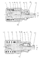
- a switch according to the present invention is provided with a sliding shaft 2 and a fixed base 3, and there is a sliding through a hole 31 on the fixed base 3, for passing the sliding shaft 2.
- the sliding shaft 2 passes the hole 31, and the head 21 of the sliding shaft 2 extends beyond the sliding through hole 31. If the head 21 of the sliding shaft 2 is connected with any extension, such extension may also extend out of sliding through hole 31 in the fixed base 3.
- a tail of the sliding shaft 2 is connected with a button 1, at tail threads of the sliding shaft 2.
- the switch has a spring 4 pushing the union body of the button 1 and the sliding shaft 2 from the head 21 of the sliding shaft 2 towards its tail.
- the spring 4 can be located between the fixed base 3 and the button 1.
- the switch is also provided with a retaining hook 6 and a fixed head of the retaining hook 6 is connected to the fixed base 3. There is a ring spring 5 for fixing the fixed head of the retaining hook 6 on an outer side of the fixed base 3.
- the spring 4 can also be located between the supporting bracket and the sliding shaft 2; the spring 4 can be positioned on the head 21 of the sliding shaft 2, inside the fixed base 3 or at any other positions where the sliding shaft 2 can obtain a force for moving from the head 21 to the tail.
- the retaining hook 6 can also be connected on a device using the present invention. The retaining hook 6 can also be connected to a part connected with the fixed base 3.
- first stop position 71 and a second stop position 72 fitting with a hook part 60 of the retaining hook 6, and the first stop position 71 and the second stop position 72 are located at different heights on the sliding shaft 2, with the first stop position 71 closer to the head 21 of the sliding shaft 2 than the second stop position.
- first unidirectional slide channel for the hook part 60 of the retaining hook 6 the first unidirectional slide channel letting the sliding shaft 2 move from a state where the first stop position 71 is fitting with the hook part 60 of the retaining hook 6 to a state where the second stop position 72 is fitting with the hook part 60 of the retaining hook 6.
- the first unidirectional slide channel comprises a first slide way section 81 starting at the first stop position 71 and a second slide-way section 82 connected with the first slide way section 81 and leading to the second stop position 72, with the connection from the second slide-way section 82 to the first slide way section 81 being farther from the head 21 of the sliding shaft 2 than the second stop position 72.
- the second unidirectional slide channel comprises a third slide way section 83 starting at the second stop position 72 and a fourth slide way section 84 connected with the third slide way section 83, with the connection from the fourth slide way section 84 to the third slide way section 83 being farther away from the head 21 of the sliding shaft 2 than the second stop position 72, and the fourth slide way section 84 is connected with the first slide way section 81 or connected to the first stop position 71.
- Relative unidirectional slide movement between the first unidirectional slide channel or the second unidirectional slide channel, and the hook part 60 can be provided through a slide channel design on a wall of the first and the second unidirectional slide channels, or a slide channel design on a bottom of the first and the second unidirectional slide channels.
- such relative unidirectional slide movement is provided through the design of the slide channel on the bottom, so that the switch has higher operation reliability and longer service life,
- Its design scheme is as follows: the first slide way section 81 and second slide way section 82 are connected in the form of a step, and at a connection 91, the bottom of the second slide way section 82 is lower than that of the first slide way section section 81.
- the third slide way section 83 and fourth slide way section 84 are connected in the form of a step, and at a connection 92, the bottom of the fourth slide way section 84 is lower than that of the third slide way section 83.
- the second slide way section 82 has a down step 93 near the second stop position 72.
- the fourth slide way section 84 and first slide way section 81 are connected in the form of a step, and at a connection 94, the bottom of the first slide way section 81 is lower than that of the fourth slide way section 84.
- a pressure force is applied on the button 1, and the button 1 drives the sliding shaft 2 to move down.
- retaining hook 6 is affected by the ring spring 5 and its fixing head is positioned on the fixed base 3.
- the hook part 60 of the retaining hook 6 moves up the first slide way section 81 from the first stop position 71.
- the hook part 60 of the retaining hook 6 moves into the second slide way section 82 at the connection 91.
- the button 1 is released, and the button 1 and the sliding shaft 2 move up under the action of spring 4, but as the first slide way section 81 and second slide way section 82 are connected in the form of a step, and at the connection 91, the channel bottom surface of the second slide way section 82 is lower than that of the first slide way section 81, the hook part 60 of the retaining hook 6 cannot move back on the original way and can only move down to the second stop position 72 area along the second channel to hook the vector point position of the second stop position 72, which is one state position of the switch and finishes downward movement of the sliding shaft 2.
- the spring 4 is compressed
- the hook part 60 of the retaining hook 6 cannot move back on the original way and can only move down to the first stop position 71 along the fourth slide way section 84 or move down into the first slide way section 81 along the fourth slide way section 84 and finally returns to the first stop position 71 and hooks the first stop position 71, which is another state position of the switch and finishes upward movement of the sliding shaft 2.
- the present invention allows manual and accurate reciprocating motion of the necessary mechanism between the upper and lower vector points (i.e., the first stop position and the second stop position) to limit positions.
- the sliding shaft 2 will drive the auxiliary mechanism to move up and down and thus provide switching on/off function.
- the switch can execute switching on/off function in the applications where liquid exist. In particular, it can execute switching on/off function widely in the field of kitchen and bathroom.
- the head 21 of the sliding shaft 2 extends out of the sliding hole in order to connect with the auxiliary structure more easily and securely. If these conveniences and effects are not taken into account, the head 21 of the sliding shaft 2 may not extend out of the sliding hole, and the auxiliary structure is connected with the head 21 of sliding shaft 2 via a connection piece.
- This embodiment is provided with a circumferential positioning mechanism for the sliding shaft 2, and fits with the immovable slide-way on sliding shaft through swinging of the hook part 60 of the retaining hook 6.
- This circumferential positioning mechanism comprises a positioning slot 22 in axial direction provided on the sliding shaft 2 and a positioning block 32 provided on the fixed base 3, the positioning block 32 is fitted with the positioning slot 22.
- the shape of the positioning block 32 can also be used for fitting with the retaining hook 6, as shown in the figure.
- the retaining hook is connected by hooking to the protruding positioning block 32 part of the fixed base 3.
- the circumferential positioning mechanism can also be the positioning channel that is provided in other position on the fixed base 3, such as inner hole.
- the protruding positioning block 32 is positioned at other corresponding position on the sliding shaft 2.
- the circumferential positioning mechanism can also be other common circumferential positioning mechanism between shaft and sleeve or provide corresponding positioning function by means of a device.
- the sliding shaft 2 can also be used to rotate by a specified angle to provide the fit between the slide-way and retaining hook 6, but it is not as convenient and comfortable in use as in the present embodiment.
- the fixed base in Embodiment 1 can also be formed by some parts connected with each other.
- the fixed base includes a mounting piece 33 and a connection sleeve 34 connected with the rear part of the mounting piece 33.
- the sliding shaft 2 is smaller near its tail or between its middle and tail and goes through the connection sleeve 34.
- the connection sleeve 34 has a small hole 35 that fits with the smaller part of the sliding shaft 2.
- the retaining hook 6 is connected by hooking on the mounting piece 33.
- a ring spring for fixing the retaining hook 6 is provided on an outer side of the mounting piece 33.
- the sealing device can be mounted on the smaller part of the sliding shaft 2 and is connected with the small hole 35 in the connection sleeve 34 in order to reduce sliding resistance and sealing difficulty, when the sliding shaft 2 must have a sealed connection with the fixed base 3.
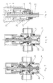
- this present invention is installed on a water diverter.
- a supporting bracket 41 for the spring 4 is mounted on the water diverter.
- the spring 4 is between the supporting bracket 41 and the valve core 23 connected with the head 21 of the sliding shaft 2. Up and down movement of the valve core 23 and sliding shaft 2 respectively turns on and off the water dispensing of upper and down sealing seats and thus provides control for upper dispensing and down dispensing.
Landscapes
- Push-Button Switches (AREA)
- Domestic Plumbing Installations (AREA)
- Massaging Devices (AREA)
- Sink And Installation For Waste Water (AREA)
- Control For Baths (AREA)
- Telephone Set Structure (AREA)
- Mechanisms For Operating Contacts (AREA)
- Drying Of Solid Materials (AREA)
- Bathtub Accessories (AREA)
- Toilet Supplies (AREA)
- Switch Cases, Indication, And Locking (AREA)
Priority Applications (1)
| Application Number | Priority Date | Filing Date | Title |
|---|---|---|---|
| PL08157505T PL2019401T3 (pl) | 2007-07-26 | 2008-06-03 | Przełącznik dla urządzeń kuchennych i łazienkowych |
Applications Claiming Priority (1)
| Application Number | Priority Date | Filing Date | Title |
|---|---|---|---|
| CNB2007100703384A CN100549482C (zh) | 2007-07-26 | 2007-07-26 | 厨卫设施的开关 |
Publications (2)
| Publication Number | Publication Date |
|---|---|
| EP2019401A1 true EP2019401A1 (de) | 2009-01-28 |
| EP2019401B1 EP2019401B1 (de) | 2011-08-17 |
Family
ID=38999269
Family Applications (1)
| Application Number | Title | Priority Date | Filing Date |
|---|---|---|---|
| EP08157505A Active EP2019401B1 (de) | 2007-07-26 | 2008-06-03 | Schalter für Küchen- und Badgeräte |
Country Status (15)
| Country | Link |
|---|---|
| US (1) | US8403297B2 (de) |
| EP (1) | EP2019401B1 (de) |
| JP (1) | JP5119328B2 (de) |
| KR (1) | KR101101099B1 (de) |
| CN (1) | CN100549482C (de) |
| AT (1) | ATE521075T1 (de) |
| AU (1) | AU2008280765B2 (de) |
| DK (1) | DK2019401T3 (de) |
| ES (1) | ES2367148T3 (de) |
| MY (1) | MY150940A (de) |
| PL (1) | PL2019401T3 (de) |
| PT (1) | PT2019401E (de) |
| RU (1) | RU2442058C2 (de) |
| UA (1) | UA95167C2 (de) |
| WO (1) | WO2009012638A1 (de) |
Cited By (1)
| Publication number | Priority date | Publication date | Assignee | Title |
|---|---|---|---|---|
| WO2016078677A1 (de) * | 2014-11-20 | 2016-05-26 | Festo Ag & Co. Kg | Mehrwegeventil |
Families Citing this family (9)
| Publication number | Priority date | Publication date | Assignee | Title |
|---|---|---|---|---|
| CN100570189C (zh) * | 2007-07-26 | 2009-12-16 | 宁波搏盛阀门管件有限公司 | 一种分水装置 |
| CN103526808B (zh) * | 2013-10-14 | 2015-09-30 | 宁波搏盛阀门管件有限公司 | 便捷式弹跳下水机构、便捷式弹跳盖和落水筒 |
| CN104696896B (zh) * | 2013-12-04 | 2019-11-12 | 海洋王(东莞)照明科技有限公司 | 锁扣连接结构及灯具 |
| CN108983021A (zh) * | 2018-06-26 | 2018-12-11 | 铜陵祥意和贸易有限责任公司 | 一种网络工程用网线测线仪 |
| CN110820875A (zh) * | 2018-08-07 | 2020-02-21 | 宁波搏盛阀门管件有限公司 | 安装方便的按压式台控及下水装置 |
| DE102019203218A1 (de) | 2019-03-08 | 2020-09-10 | Hansgrohe Se | Wandmontierbare sanitäre Leitungsanschlussvorrichtung mit integriertem Ventil |
| CN110961438A (zh) * | 2019-12-30 | 2020-04-07 | 浙江揭迪智能科技有限公司 | 餐厨垃圾综合处理装置 |
| CN113802676A (zh) * | 2020-06-17 | 2021-12-17 | 宁波搏盛阀门管件有限公司 | 下沉开关式地漏 |
| CN116905630B (zh) * | 2023-08-02 | 2024-05-14 | 天元建设集团有限公司 | 雨水井排水装置及其控制方法 |
Citations (3)
| Publication number | Priority date | Publication date | Assignee | Title |
|---|---|---|---|---|
| US4354074A (en) * | 1981-07-01 | 1982-10-12 | Honeywell Inc. | Alternate action mechanism |
| GB2206237A (en) * | 1987-06-05 | 1988-12-29 | Telemecanique Electrique | Latchable switches |
| EP0721196A1 (de) * | 1995-01-06 | 1996-07-10 | Kabushiki Kaisha Tokai-Rika-Denki-Seisakusho | Verriegelbarer Tastschalter |
Family Cites Families (28)
| Publication number | Priority date | Publication date | Assignee | Title |
|---|---|---|---|---|
| US617391A (en) * | 1899-01-10 | Frederick berner | ||
| US2219105A (en) * | 1940-02-08 | 1940-10-22 | Keystone Brass & Rubber Co | Diverter valve |
| US2592361A (en) * | 1950-10-26 | 1952-04-08 | Shakespeare Products Co | Remote control device for heaters, valves, and other remote controlled parts |
| US3288973A (en) * | 1965-04-16 | 1966-11-29 | Cutler Hammer Inc | Push-push switch convertible to momentary switch |
| JPS5211424B1 (de) * | 1971-03-27 | 1977-03-31 | ||
| JPS4895161U (de) * | 1972-02-12 | 1973-11-13 | ||
| SU414438A1 (de) * | 1972-06-14 | 1974-02-05 | ||
| SU460406A1 (ru) * | 1972-12-25 | 1975-02-15 | Московский энергетический институт | Электромеханический институт |
| JPS50140920A (de) * | 1974-04-26 | 1975-11-12 | ||
| GB1501551A (en) * | 1975-03-08 | 1978-02-15 | Grohe Handels Gmbh | Sanitary fittings |
| JPS5719909Y2 (de) * | 1979-09-11 | 1982-04-27 | ||
| JPS60121376A (ja) * | 1983-12-03 | 1985-06-28 | Rinnai Corp | 押圧操作装置 |
| JPS60170931U (ja) * | 1984-04-20 | 1985-11-13 | アルプス電気株式会社 | プッシュ・プッシュスイッチ |
| FR2566503B1 (fr) * | 1984-06-20 | 1986-12-19 | Joucomatic Sa | Dispositif de securite pour vannes ou robinets motorises ou manuels |
| JPH01119132U (de) * | 1988-02-08 | 1989-08-11 | ||
| US4982762A (en) * | 1989-03-15 | 1991-01-08 | Deere & Company | Hydraulic lift with weight transfer |
| CN1013218B (zh) * | 1989-12-22 | 1991-07-17 | 綦建前 | 缸式阀 |
| JPH05203142A (ja) * | 1992-01-29 | 1993-08-10 | Harman Co Ltd | ガス制御装置 |
| JPH05266755A (ja) * | 1992-03-18 | 1993-10-15 | Hitachi Ltd | 押釦スイッチ |
| CN2165294Y (zh) * | 1993-04-21 | 1994-05-18 | 欧阳敏 | 常闭式节水阀 |
| JPH08148057A (ja) * | 1994-11-22 | 1996-06-07 | Yazaki Corp | 押ボタンスイッチ |
| US5768718A (en) | 1995-07-26 | 1998-06-23 | Katoh Electrial Machinery Co., Ltd. | Control device for controlling the seat or the seat lid of a toilet bowl |
| JP2001082558A (ja) * | 1999-09-09 | 2001-03-27 | Ntn Corp | チェーンテンショナ |
| US6173910B1 (en) * | 1999-10-14 | 2001-01-16 | Chya Ye Industrial Co., Ltd. | Press structure of washing head for kitchen cabinet |
| JP4242714B2 (ja) * | 2003-06-23 | 2009-03-25 | 株式会社ケーブイケー | 水栓 |
| CN2898489Y (zh) * | 2005-01-18 | 2007-05-09 | 周传藻 | 可控量、快开闭、脂压定水量龙头 |
| CN2898488Y (zh) * | 2005-01-18 | 2007-05-09 | 周传藻 | 快速开闭、可控流量、自关水龙头 |
| GB0615925D0 (en) * | 2006-08-10 | 2006-09-20 | Williamson Robert | Improvements in or relating to tap adaptors |
-
2007
- 2007-07-26 CN CNB2007100703384A patent/CN100549482C/zh active Active
-
2008
- 2008-02-13 WO PCT/CN2008/000341 patent/WO2009012638A1/zh not_active Ceased
- 2008-02-13 AU AU2008280765A patent/AU2008280765B2/en not_active Ceased
- 2008-02-13 RU RU2010107034/06A patent/RU2442058C2/ru not_active IP Right Cessation
- 2008-02-13 UA UAA201002030A patent/UA95167C2/ru unknown
- 2008-02-13 KR KR1020107002367A patent/KR101101099B1/ko not_active Expired - Fee Related
- 2008-02-13 MY MYPI20095098 patent/MY150940A/en unknown
- 2008-02-13 JP JP2010517250A patent/JP5119328B2/ja not_active Expired - Fee Related
- 2008-06-03 PL PL08157505T patent/PL2019401T3/pl unknown
- 2008-06-03 ES ES08157505T patent/ES2367148T3/es active Active
- 2008-06-03 DK DK08157505.2T patent/DK2019401T3/da active
- 2008-06-03 PT PT08157505T patent/PT2019401E/pt unknown
- 2008-06-03 EP EP08157505A patent/EP2019401B1/de active Active
- 2008-06-03 AT AT08157505T patent/ATE521075T1/de not_active IP Right Cessation
- 2008-07-21 US US12/219,361 patent/US8403297B2/en active Active
Patent Citations (3)
| Publication number | Priority date | Publication date | Assignee | Title |
|---|---|---|---|---|
| US4354074A (en) * | 1981-07-01 | 1982-10-12 | Honeywell Inc. | Alternate action mechanism |
| GB2206237A (en) * | 1987-06-05 | 1988-12-29 | Telemecanique Electrique | Latchable switches |
| EP0721196A1 (de) * | 1995-01-06 | 1996-07-10 | Kabushiki Kaisha Tokai-Rika-Denki-Seisakusho | Verriegelbarer Tastschalter |
Cited By (1)
| Publication number | Priority date | Publication date | Assignee | Title |
|---|---|---|---|---|
| WO2016078677A1 (de) * | 2014-11-20 | 2016-05-26 | Festo Ag & Co. Kg | Mehrwegeventil |
Also Published As
| Publication number | Publication date |
|---|---|
| EP2019401B1 (de) | 2011-08-17 |
| DK2019401T3 (da) | 2011-09-26 |
| KR20100039384A (ko) | 2010-04-15 |
| RU2010107034A (ru) | 2011-09-10 |
| WO2009012638A1 (fr) | 2009-01-29 |
| CN101105245A (zh) | 2008-01-16 |
| UA95167C2 (ru) | 2011-07-11 |
| US8403297B2 (en) | 2013-03-26 |
| JP5119328B2 (ja) | 2013-01-16 |
| JP2010534900A (ja) | 2010-11-11 |
| MY150940A (en) | 2014-03-14 |
| KR101101099B1 (ko) | 2012-01-03 |
| PT2019401E (pt) | 2011-09-05 |
| CN100549482C (zh) | 2009-10-14 |
| ATE521075T1 (de) | 2011-09-15 |
| AU2008280765B2 (en) | 2012-02-09 |
| ES2367148T3 (es) | 2011-10-28 |
| RU2442058C2 (ru) | 2012-02-10 |
| AU2008280765A1 (en) | 2009-01-29 |
| US20090026403A1 (en) | 2009-01-29 |
| PL2019401T3 (pl) | 2012-01-31 |
Similar Documents
| Publication | Publication Date | Title |
|---|---|---|
| EP2019401B1 (de) | Schalter für Küchen- und Badgeräte | |
| EP2020547B1 (de) | Wasserableitungsvorrichtung | |
| US9707574B2 (en) | Diverter valve assembly and shower system | |
| US9816257B2 (en) | Sensor assembly for faucet | |
| RU2511181C2 (ru) | Арматура с электронным управлением | |
| US10443219B2 (en) | Faucets providing water-and-air flow | |
| US10364557B2 (en) | Faucets providing mixed water and air flow | |
| US10443218B2 (en) | Faucets providing mixed water and air flow | |
| US12065813B2 (en) | Faucet with cantilevered support arm | |
| US8220480B2 (en) | Sanitary fitting | |
| KR101912179B1 (ko) | 기능성 복합 수도밸브 | |
| CN216156714U (zh) | 水槽用按压式水塞 | |
| KR101248521B1 (ko) | 절수형 밸브 개폐장치 | |
| CA2990926C (en) | Faucets providing mixed water and air flow | |
| CN110005023B (zh) | 水龙头 | |
| CA2990920C (en) | Faucets providing mixed water and air flow | |
| JP2016098578A (ja) | 自動水栓 |
Legal Events
| Date | Code | Title | Description |
|---|---|---|---|
| PUAI | Public reference made under article 153(3) epc to a published international application that has entered the european phase |
Free format text: ORIGINAL CODE: 0009012 |
|
| AK | Designated contracting states |
Kind code of ref document: A1 Designated state(s): AT BE BG CH CY CZ DE DK EE ES FI FR GB GR HR HU IE IS IT LI LT LU LV MC MT NL NO PL PT RO SE SI SK TR |
|
| AX | Request for extension of the european patent |
Extension state: AL BA MK RS |
|
| 17P | Request for examination filed |
Effective date: 20090727 |
|
| AKX | Designation fees paid |
Designated state(s): AT BE BG CH CY CZ DE DK EE ES FI FR GB GR HR HU IE IS IT LI LT LU LV MC MT NL NO PL PT RO SE SI SK TR |
|
| 17Q | First examination report despatched |
Effective date: 20100225 |
|
| GRAP | Despatch of communication of intention to grant a patent |
Free format text: ORIGINAL CODE: EPIDOSNIGR1 |
|
| RIN1 | Information on inventor provided before grant (corrected) |
Inventor name: CEN, DIFENG |
|
| GRAS | Grant fee paid |
Free format text: ORIGINAL CODE: EPIDOSNIGR3 |
|
| GRAA | (expected) grant |
Free format text: ORIGINAL CODE: 0009210 |
|
| AK | Designated contracting states |
Kind code of ref document: B1 Designated state(s): AT BE BG CH CY CZ DE DK EE ES FI FR GB GR HR HU IE IS IT LI LT LU LV MC MT NL NO PL PT RO SE SI SK TR |
|
| REG | Reference to a national code |
Ref country code: GB Ref legal event code: FG4D |
|
| REG | Reference to a national code |
Ref country code: CH Ref legal event code: EP |
|
| REG | Reference to a national code |
Ref country code: PT Ref legal event code: SC4A Free format text: AVAILABILITY OF NATIONAL TRANSLATION Effective date: 20110826 |
|
| REG | Reference to a national code |
Ref country code: IE Ref legal event code: FG4D |
|
| REG | Reference to a national code |
Ref country code: NL Ref legal event code: T3 |
|
| REG | Reference to a national code |
Ref country code: DK Ref legal event code: T3 |
|
| REG | Reference to a national code |
Ref country code: DE Ref legal event code: R096 Ref document number: 602008008885 Country of ref document: DE Effective date: 20111013 |
|
| REG | Reference to a national code |
Ref country code: ES Ref legal event code: FG2A Ref document number: 2367148 Country of ref document: ES Kind code of ref document: T3 Effective date: 20111028 |
|
| REG | Reference to a national code |
Ref country code: SE Ref legal event code: TRGR |
|
| LTIE | Lt: invalidation of european patent or patent extension |
Effective date: 20110817 |
|
| PG25 | Lapsed in a contracting state [announced via postgrant information from national office to epo] |
Ref country code: LT Free format text: LAPSE BECAUSE OF FAILURE TO SUBMIT A TRANSLATION OF THE DESCRIPTION OR TO PAY THE FEE WITHIN THE PRESCRIBED TIME-LIMIT Effective date: 20110817 Ref country code: NO Free format text: LAPSE BECAUSE OF FAILURE TO SUBMIT A TRANSLATION OF THE DESCRIPTION OR TO PAY THE FEE WITHIN THE PRESCRIBED TIME-LIMIT Effective date: 20111117 Ref country code: FI Free format text: LAPSE BECAUSE OF FAILURE TO SUBMIT A TRANSLATION OF THE DESCRIPTION OR TO PAY THE FEE WITHIN THE PRESCRIBED TIME-LIMIT Effective date: 20110817 Ref country code: IS Free format text: LAPSE BECAUSE OF FAILURE TO SUBMIT A TRANSLATION OF THE DESCRIPTION OR TO PAY THE FEE WITHIN THE PRESCRIBED TIME-LIMIT Effective date: 20111217 |
|
| REG | Reference to a national code |
Ref country code: PL Ref legal event code: T3 |
|
| REG | Reference to a national code |
Ref country code: AT Ref legal event code: MK05 Ref document number: 521075 Country of ref document: AT Kind code of ref document: T Effective date: 20110817 |
|
| PG25 | Lapsed in a contracting state [announced via postgrant information from national office to epo] |
Ref country code: CY Free format text: LAPSE BECAUSE OF FAILURE TO SUBMIT A TRANSLATION OF THE DESCRIPTION OR TO PAY THE FEE WITHIN THE PRESCRIBED TIME-LIMIT Effective date: 20110817 Ref country code: SI Free format text: LAPSE BECAUSE OF FAILURE TO SUBMIT A TRANSLATION OF THE DESCRIPTION OR TO PAY THE FEE WITHIN THE PRESCRIBED TIME-LIMIT Effective date: 20110817 Ref country code: AT Free format text: LAPSE BECAUSE OF FAILURE TO SUBMIT A TRANSLATION OF THE DESCRIPTION OR TO PAY THE FEE WITHIN THE PRESCRIBED TIME-LIMIT Effective date: 20110817 Ref country code: LV Free format text: LAPSE BECAUSE OF FAILURE TO SUBMIT A TRANSLATION OF THE DESCRIPTION OR TO PAY THE FEE WITHIN THE PRESCRIBED TIME-LIMIT Effective date: 20110817 Ref country code: GR Free format text: LAPSE BECAUSE OF FAILURE TO SUBMIT A TRANSLATION OF THE DESCRIPTION OR TO PAY THE FEE WITHIN THE PRESCRIBED TIME-LIMIT Effective date: 20111118 |
|
| PG25 | Lapsed in a contracting state [announced via postgrant information from national office to epo] |
Ref country code: BE Free format text: LAPSE BECAUSE OF FAILURE TO SUBMIT A TRANSLATION OF THE DESCRIPTION OR TO PAY THE FEE WITHIN THE PRESCRIBED TIME-LIMIT Effective date: 20110817 |
|
| PG25 | Lapsed in a contracting state [announced via postgrant information from national office to epo] |
Ref country code: CZ Free format text: LAPSE BECAUSE OF FAILURE TO SUBMIT A TRANSLATION OF THE DESCRIPTION OR TO PAY THE FEE WITHIN THE PRESCRIBED TIME-LIMIT Effective date: 20110817 Ref country code: SK Free format text: LAPSE BECAUSE OF FAILURE TO SUBMIT A TRANSLATION OF THE DESCRIPTION OR TO PAY THE FEE WITHIN THE PRESCRIBED TIME-LIMIT Effective date: 20110817 |
|
| PG25 | Lapsed in a contracting state [announced via postgrant information from national office to epo] |
Ref country code: RO Free format text: LAPSE BECAUSE OF FAILURE TO SUBMIT A TRANSLATION OF THE DESCRIPTION OR TO PAY THE FEE WITHIN THE PRESCRIBED TIME-LIMIT Effective date: 20110817 Ref country code: EE Free format text: LAPSE BECAUSE OF FAILURE TO SUBMIT A TRANSLATION OF THE DESCRIPTION OR TO PAY THE FEE WITHIN THE PRESCRIBED TIME-LIMIT Effective date: 20110817 |
|
| PLBE | No opposition filed within time limit |
Free format text: ORIGINAL CODE: 0009261 |
|
| STAA | Information on the status of an ep patent application or granted ep patent |
Free format text: STATUS: NO OPPOSITION FILED WITHIN TIME LIMIT |
|
| 26N | No opposition filed |
Effective date: 20120521 |
|
| PG25 | Lapsed in a contracting state [announced via postgrant information from national office to epo] |
Ref country code: HR Free format text: LAPSE BECAUSE OF FAILURE TO SUBMIT A TRANSLATION OF THE DESCRIPTION OR TO PAY THE FEE WITHIN THE PRESCRIBED TIME-LIMIT Effective date: 20120321 |
|
| REG | Reference to a national code |
Ref country code: DE Ref legal event code: R097 Ref document number: 602008008885 Country of ref document: DE Effective date: 20120521 |
|
| PG25 | Lapsed in a contracting state [announced via postgrant information from national office to epo] |
Ref country code: MC Free format text: LAPSE BECAUSE OF NON-PAYMENT OF DUE FEES Effective date: 20120630 |
|
| REG | Reference to a national code |
Ref country code: CH Ref legal event code: PL |
|
| REG | Reference to a national code |
Ref country code: CH Ref legal event code: PL |
|
| REG | Reference to a national code |
Ref country code: IE Ref legal event code: MM4A |
|
| PG25 | Lapsed in a contracting state [announced via postgrant information from national office to epo] |
Ref country code: IE Free format text: LAPSE BECAUSE OF NON-PAYMENT OF DUE FEES Effective date: 20120603 Ref country code: CH Free format text: LAPSE BECAUSE OF NON-PAYMENT OF DUE FEES Effective date: 20120630 Ref country code: LI Free format text: LAPSE BECAUSE OF NON-PAYMENT OF DUE FEES Effective date: 20120630 |
|
| PG25 | Lapsed in a contracting state [announced via postgrant information from national office to epo] |
Ref country code: BG Free format text: LAPSE BECAUSE OF FAILURE TO SUBMIT A TRANSLATION OF THE DESCRIPTION OR TO PAY THE FEE WITHIN THE PRESCRIBED TIME-LIMIT Effective date: 20111117 |
|
| PG25 | Lapsed in a contracting state [announced via postgrant information from national office to epo] |
Ref country code: HR Free format text: LAPSE BECAUSE OF FAILURE TO SUBMIT A TRANSLATION OF THE DESCRIPTION OR TO PAY THE FEE WITHIN THE PRESCRIBED TIME-LIMIT Effective date: 20110817 |
|
| PG25 | Lapsed in a contracting state [announced via postgrant information from national office to epo] |
Ref country code: LU Free format text: LAPSE BECAUSE OF NON-PAYMENT OF DUE FEES Effective date: 20120603 |
|
| PG25 | Lapsed in a contracting state [announced via postgrant information from national office to epo] |
Ref country code: HU Free format text: LAPSE BECAUSE OF FAILURE TO SUBMIT A TRANSLATION OF THE DESCRIPTION OR TO PAY THE FEE WITHIN THE PRESCRIBED TIME-LIMIT Effective date: 20080603 |
|
| REG | Reference to a national code |
Ref country code: FR Ref legal event code: PLFP Year of fee payment: 9 |
|
| PGFP | Annual fee paid to national office [announced via postgrant information from national office to epo] |
Ref country code: PT Payment date: 20160525 Year of fee payment: 9 Ref country code: SE Payment date: 20160623 Year of fee payment: 9 Ref country code: DK Payment date: 20160623 Year of fee payment: 9 |
|
| REG | Reference to a national code |
Ref country code: FR Ref legal event code: PLFP Year of fee payment: 10 |
|
| REG | Reference to a national code |
Ref country code: DK Ref legal event code: EBP Effective date: 20170630 |
|
| REG | Reference to a national code |
Ref country code: SE Ref legal event code: EUG |
|
| PG25 | Lapsed in a contracting state [announced via postgrant information from national office to epo] |
Ref country code: PT Free format text: LAPSE BECAUSE OF NON-PAYMENT OF DUE FEES Effective date: 20171204 Ref country code: SE Free format text: LAPSE BECAUSE OF NON-PAYMENT OF DUE FEES Effective date: 20170604 |
|
| REG | Reference to a national code |
Ref country code: FR Ref legal event code: PLFP Year of fee payment: 11 |
|
| PG25 | Lapsed in a contracting state [announced via postgrant information from national office to epo] |
Ref country code: DK Free format text: LAPSE BECAUSE OF NON-PAYMENT OF DUE FEES Effective date: 20170630 |
|
| PG25 | Lapsed in a contracting state [announced via postgrant information from national office to epo] |
Ref country code: MT Free format text: LAPSE BECAUSE OF NON-PAYMENT OF DUE FEES Effective date: 20170603 |
|
| PGFP | Annual fee paid to national office [announced via postgrant information from national office to epo] |
Ref country code: MT Payment date: 20160603 Year of fee payment: 9 |
|
| REG | Reference to a national code |
Ref country code: DE Ref legal event code: R082 Ref document number: 602008008885 Country of ref document: DE Representative=s name: HL KEMPNER PATENTANWAELTE, SOLICITORS (ENGLAND, DE Ref country code: DE Ref legal event code: R082 Ref document number: 602008008885 Country of ref document: DE Representative=s name: HL KEMPNER PATENTANWALT, RECHTSANWALT, SOLICIT, DE Ref country code: DE Ref legal event code: R082 Ref document number: 602008008885 Country of ref document: DE Representative=s name: HL KEMPNER PARTG MBB, DE |
|
| PGFP | Annual fee paid to national office [announced via postgrant information from national office to epo] |
Ref country code: IT Payment date: 20210614 Year of fee payment: 14 Ref country code: NL Payment date: 20210617 Year of fee payment: 14 Ref country code: FR Payment date: 20210610 Year of fee payment: 14 |
|
| PGFP | Annual fee paid to national office [announced via postgrant information from national office to epo] |
Ref country code: TR Payment date: 20210531 Year of fee payment: 14 Ref country code: PL Payment date: 20210525 Year of fee payment: 14 |
|
| PGFP | Annual fee paid to national office [announced via postgrant information from national office to epo] |
Ref country code: ES Payment date: 20210716 Year of fee payment: 14 |
|
| REG | Reference to a national code |
Ref country code: NL Ref legal event code: MM Effective date: 20220701 |
|
| PG25 | Lapsed in a contracting state [announced via postgrant information from national office to epo] |
Ref country code: NL Free format text: LAPSE BECAUSE OF NON-PAYMENT OF DUE FEES Effective date: 20220701 |
|
| PG25 | Lapsed in a contracting state [announced via postgrant information from national office to epo] |
Ref country code: FR Free format text: LAPSE BECAUSE OF NON-PAYMENT OF DUE FEES Effective date: 20220630 |
|
| REG | Reference to a national code |
Ref country code: ES Ref legal event code: FD2A Effective date: 20230726 |
|
| PG25 | Lapsed in a contracting state [announced via postgrant information from national office to epo] |
Ref country code: IT Free format text: LAPSE BECAUSE OF NON-PAYMENT OF DUE FEES Effective date: 20220603 |
|
| PG25 | Lapsed in a contracting state [announced via postgrant information from national office to epo] |
Ref country code: ES Free format text: LAPSE BECAUSE OF NON-PAYMENT OF DUE FEES Effective date: 20220604 |
|
| PG25 | Lapsed in a contracting state [announced via postgrant information from national office to epo] |
Ref country code: PL Free format text: LAPSE BECAUSE OF NON-PAYMENT OF DUE FEES Effective date: 20220603 |
|
| PG25 | Lapsed in a contracting state [announced via postgrant information from national office to epo] |
Ref country code: TR Free format text: LAPSE BECAUSE OF NON-PAYMENT OF DUE FEES Effective date: 20220603 |
|
| PGFP | Annual fee paid to national office [announced via postgrant information from national office to epo] |
Ref country code: DE Payment date: 20250623 Year of fee payment: 18 |
|
| PGFP | Annual fee paid to national office [announced via postgrant information from national office to epo] |
Ref country code: GB Payment date: 20250624 Year of fee payment: 18 |